
Volume 8, Number 1, March 2005
Weapons Effects Prediction—Firing For Effect
- 1 Defence Science and Technology Organisation, PO Box 1500, Edinburgh SA Australia 5111.
Abstract
This study presents two practical approaches to assisting military staff plan for effects on the battlefield. First, a calculator tool for the effects of known indirect-fire weapons systems upon targets is provided. The method in which effects are calculated is based on Australian and United States military doctrine. Using this tool, staff are able to evaluate the effects produced upon targets without consulting tables of ammunition effects or performing complicated calculations. Second, a practical solution to the problem of allocating these indirect-fire weapons systems to targets in order to produce desired effects is discussed. In solving this problem, it is not assumed that targets are necessarily detected, identified or recognised. A sequence of Monte Carlo simulations is conducted to predict the nature of the effects produced. No judgement is made on the relative merits of the effects produced in any of the possible allocations. Hence, the Weapons Effects Prediction software assists, but does not replace, military staff in planning for effects on the battlefield.
Introduction
The translation between planning for desired effects on the battlefield and the production of these effects using indirect-fire assets such as Artillery, Mortar, Naval Gunfire Support and Close Air Support is often a lengthy and difficult process. As a result, Australian military staff are extensively trained to plan for the generation of desired effects and to allocate indirect-fire assets both efficiently and effectively in an environment of conflicting priorities and possibly insufficient resources. This study develops weapons effects software to assist staff in conducting effects planning.
We provide a user with a simple tool to calculate the effects produced by various combinations of weapons systems and mixes of ammunition. This tool is developed using the open-source software OpenMap [14]. OpenMap is a geographic-information-system viewing tool. That is, its main functionality lies in the display of graphics and overlays. We define this combination of graphics and overlays loosely as a map. The user of this tool is able to place weapons systems and targets onto the map, as well as setting various attributes of the systems such as ammunition, and can designate targets for the weapons systems. The Weapons Effects Predictor provides a calculation of the effects produced on each of the targets as an output. This calculation is based on Australian and American military doctrine. Specifically, the Australian Manuals of Land Warfare [5; 11], Corps Training Notes [2; 3; 6; 7; 9] and Land Warfare Procedures [10] are used as well as the United States Army and the United States Joint Services Field Manuals [18–26] Technical Manuals [16] and Special Texts [19].
Inherent in the calculation of effects is the assumption that the weapons platforms are able to engage and prosecute the targets designated to them by the user. A prediction of effects is also provided. In making this prediction the assumption is made that a target may not necessarily be detected. The user is able to change the probability that a given target is detected in three ways. First, the user may change the perceived comparative likelihood of detecting each target. For example, it is easier to detect a regiment of tanks than it is to detect a platoon of infantry. Second, the user may change the perceived ability to successfully conduct Intelligence, Surveillance, Target Acquisition and Reconnaissance (ISTAR) operations in a given area of the map of fixed size. For example, it is easier to detect a company of infantry using all available ISTAR systems than it is to detect the same company of infantry using no ISTAR systems at all. Third, the user may change the size of the area to be searched when looking for the enemy. For example, it is easier to detect a target known or suspected to be hiding in a small forest than it is to detect the same target hiding in a large forest. The Weapons Effects Predictor provides an estimation of the relative likelihood of successfully engaging and producing effects on targets as an output.
The allocation of weapons systems to targets is a non-trivial task, made so primarily by the inability to differentiate between the relative merits of two or more different effects. For example, when engaging three enemy tanks would you rather (a) completely destroy one of the tanks, or (b) disable two of the tanks for six hours. The answer to this relatively simple question depends on the original intent of the commander in engaging the enemy. Assume that a commander wishes to retreat from the battlefield and to ensure the safety of his forces after this retreat. Which of the two options (a) or (b) best fulfils this intent? The Weapons Effects Predictor does not replace human decision makers but instead provides a list of possible effects, and the corresponding target designation information, to the user. For the simulation of effects, we have chosen to use Quinone [12]. Quinone, developed by Alistair Dickie for the Australian Defence Force as a part of Project Albert, is an extension of the open-source discrete-event-simulation software Simkit [15], developed by Kirk Stork and Arnold Buss for the United States Naval Postgraduate School. Simkit is a suite of Java classes facilitating the simulation of continuous or discrete time processes that generates discrete-events. For example, Simkit could be used to simulate the queues at a bank or a game of monopoly. Quinone is an extension of Simkit that is specifically designed to model weapons platforms and includes a visualisation window for the purpose of observing the system. The Weapons Effects Predictor links to Simkit/Quinone to provide the user with options for possible effects and target designations.
Model
Definition of terms
Before explaining how the Weapons Effects Predictor works, we first explain the terms used throughout this paper. Specifically, we discuss what is meant by an effect and then introduce the concepts of suppression, neutralisation and destruction. Refer to [4, p. 3–2; 5§3-4; 8, p. 3; 18, pp. C-3,4] for a concise definition of effects.
Effects: The effect that indirect fire has upon targets is divided into two categories as follows:
- Physical: Direct damage or injury inflicted by the blast and fragmentation of indirect fire. Damage is further described as material when inflicted upon equipment and fieldwork. Injury is further described as lethal when inflicted upon personnel as casualties.
- Psychological: Reduction in the efficiency, effectiveness and ability of targets to engage in combat. Psychological effects typically include shock and loss of morale.
The extent of the physical and psychological effects experienced by targets defines what is meant by suppression, neutralisation and destruction. However, we have not adopted a rigorous definition of these terms. For example: destruction is often defined as rendering thirty percent of targets permanently inoperable, neutralisation is often defined as rendering ten to twenty percent of targets temporarily unable to engage in combat for a period of twelve to twenty four hours, while suppression is often defined as preventing effective enemy fire upon friendly units. Instead we have adopted a simpler definition of suppression, neutralization and destruction as follows:
- Suppression: Ten percent of targets sustain physical or psychological effects.
- Neutralisation: Twenty percent of targets sustain physical or psychological effects.
- Destruction: Thirty percent of targets sustain physical or psychological effects.
Weapons systems and targets
The characteristics of eight Indirect Fire Weapons Systems, in common use by the Australian and coalition forces, are modelled in this study. These systems are listed in Table 1. The rate of fire, in rounds per minute, for the weapons systems is measured based on the sustainable rate of fire for the system (St) and the maximum rate of fire for the system (Mx) over the first one minute of action. The actual rate of fire used by the gun depends on the effect desired. For example, it is likely that the sustained rate of fire would be used for suppression. The ammunition compatibility column classifies the type of rounds each system fires.
Values listed in Table 1 are taken from an Indirect Fire Weapons Systems engagement systems study [1] that in turn cites a number of sources [2; 9; 10; 13]. An effort has been made to ensure that the values used in Table 1 are accurate. However, it is difficult to obtain agreement between sources because of inherent variations in measurement of these values and the way in which these values are presented. For example, rate of fire depends upon the competence of the crew manning the system as well as factors inherent to the system itself. Also, the maximum rate of fire is often reported over different time periods, 1 minute, 3 minutes and 10 minutes are commonly used.
| Weapons System | Rate | Ammunition Compatibility | |
|---|---|---|---|
| Mn | Mx | ||
| M252 81-mm Mortar | 8 | 25 | M253 |
| 120-mm M120 Mortar | 4 | 16 | Smoothbore |
| GMD 120-mm LAV III mounted self-propelled mortar | 4 | 10 | Smoothbore |
| 105-mm M2A2 Howitzer | 3 | 6 | US M1 |
| Hamel 105-mm L118 Howitzer | 3 | 6 | Abbot Mk2 |
| Hamel 105-mm L119 Howitzer | 3 | 6 | US M1 |
| Paladin 155-mm M109A6 self-propelled Howitzer | 1 | 4 | M284 39-Cal |
| 155-mm M198 Howitzer | 2 | 4 | M107 |
For the purpose of this study, the Indirect Fire Weapons Systems are categorised as units based on the following standard configurations. Mortar is categorised in terms of Mortar Sections and Mortar Platoons. Artillery is categorised in terms of Batteries and Regiments.
Seven types of targets are considered in this study. These are based on generic descriptions of a type of target rather than specific threat weapons systems. The targets studied are: Armour, Mechanised Infantry, Infantry in the open, Infantry in a trench, Infantry under full cover, Mortar and Artillery.
For the purpose of this study, targets are categorised as units based on the following standard configurations [4, p. 4-V-4]. Armour is categorised in terms of a Troop of 3–4 Main Battle Tanks, a Squadron of 10–13 Main Battle Tanks and a Regiment of 36–40 Main Battle Tanks. Mechanised Infantry is categorised in terms of a Platoon of 30 personnel in 3–4 Armoured Personnel Carriers (APCs), a Company of 90 personnel in 10–13 APCs and a Battalion of 430 personnel in 36–40 APCs. Mortar is categorised in terms of a Section of 2 delivery systems and a Platoon of 6–8 delivery systems. Artillery is categorised in terms of a Battery of 6 delivery systems and a Regiment of 18 delivery systems.
Ammunition characteristics and effects
A number of types of ammunition [3, §1; 4, pp. 4-III-1,2; 5, §3-2, §7, §18-3; 17, §B-10; 18, §C-11], in common use by the Australian and coalition forces, are modelled in this study. Ammunition types include:
- Anti-Personnel Improved Conventional Munitions (APICM);
- Army Tactical Missile System (ATacMS);
- Copperhead (Cphd);
- Dual Purpose Improved Conventional Munitions (DPICM);
- High Explosive (HE);
- High Explosive, Rocket Assisted Projectile (RAP);
- Improved Conventional Munition (ICM);
- Illumination (Illum);
- Remote Anti-Armour Munition (RAAM); and
- White Phosphorous (WP).
Rounds are further differentiated by diameter—for example, 81 mm, 105 mm, 120 mm and 155 mm. Rounds may be fused [3, §1; 5, §3-2; 7, pp. 6-15,16,17,53,54; 21, §10–17] in a number of different ways depending on the type of ammunition and the intended effect. Fuses include:
- Concrete Piercing (CP);
- Delayed (Dly);
- Point Detonating (PD);,
- Mechanical Time (MT);
- Mechanical Time Super Quick (MTSQ); and
- Variable Time (VT).
Note that Naval Gunfire Support [1, p. 4-VI-1] and Offensive Air Support [3, §2; 4, pp. 4-VII-5,6,7,8] are included in this study. We model 76-mm and 5-inch Naval Gunfire Support, cruise missiles deployed against land targets and bomb types including air-delivered free-fall precision-guided-munition (PGM), air-delivered free-fall non-PGM, rocket assisted PGM and rocket powered PGM. Multiple Launch Rocket Systems [19; 23] are also modelled. These systems launch ATacMS missiles as well as HE and DPICM ammunitions. For convenience, we henceforth refer to all types of ordinance delivered by the systems in this study as loosely as rounds rather than specially distinguishing between shells, rounds, missiles and bombs.
Each particular round is associated with a lethal area [5, §7 AnnexC; 7, pp. 6A-1-8; 14, §B-2,3,7; 25; 26] description. Rounds for which lethal areas not strictly meaningful in a literal sense, smoke and illumination for example, are still associated with lethal area descriptions. However, the software interprets these values simply as the areas over which the rounds have effect. For the purpose of simplicity, we define the boundaries of these areas as simple geometric shapes such as ellipses or convex polygons. Descriptions of the minimum safe distances for the rounds are also recorded. Lethal areas and minimum safe distances are not directly used in this study, apart from displaying these regions on users’ screens.
For each Indirect Fire Weapon System given in Table 1 and each type of round, the minimum and maximum ranges of the weapon systems and rounds are recorded [4, pp. 4-V-3,4; 18, §C-7,8,9]. These values are displayed on users’ screens. Furthermore, information on the numbers of rounds required to achieve each of the effects suppression, neutralisation and destruction against each type of target in the study is recorded. Table 2 displays the numbers of 155-mm HE, DPICM, APICM and Cphd rounds with PD fuses required to suppress Troops, Squadrons and Regiments of Armour, such as Main Battle Tanks. Ammunition types that are not deemed effective against armour are denoted with a ‘-‘.
For security reasons the values in Table 2 are presented for demonstration purposes only and are not representative of actual combat data.
| Target: Armour | Suppression | |||
|---|---|---|---|---|
| HE | DPICM | APICM | Cphd | |
| Troop (Tp) | 50 | 20 | – | 1 |
| Squadron (Sqn) | 100 | 40 | – | 1 |
| Regiment (Regt) | 150 | 100 | – | 4 |
This study does not directly model the range or trajectory over which rounds are fired. Nor does this study account for the reliability of various types of rounds or non-standard tactical dispersals of targets. Values in Table 2 are interpreted as the average number of rounds required to achieve effects in generic conventional battles and are not specifically tailored to any particular scenario. A ballistics model and a terrain model, addressing these limitations, are planned for a further study.
Notice that the values given in Table 2 do not explicitly take into account the durations over which rounds are fired. That is, a value of 6 rounds could be interpreted as six weapons systems firing a single salvo or a single weapon system firing 6 rounds. Hence, we rely on a user to input a realistic fire plan [5, §7-15]. However, the fire rates for the weapon system is known, see for example Table 1. The Weapons Effects Predictor alerts the user to fire plans that exceed a user-defined duration: 1 hour, 6 hours or 24 hours for example. It is acknowledged that the time independence of the table is somewhat simplistic. A more realistic method for the calculation of effects is planned in a further study.
Weapons effects modelling
The Weapons Effects Predictor using the Geographic Information System (GIS) software OpenMap is developed for users as follows. Users are presented with a battlemap displayed as a graphic and are able to define Targeted Areas of Interest (TAIs) on this map. These TAIs are restricted to simple geometric shapes such as ellipses or convex polygons. Hence, their area can be easily calculated. Next a number of blue-force (friendly) Indirect Fire Weapons Systems are placed onto the map. These include those platforms listed in Table 1 as well as symbols representing Naval Gunfire Support, Close Air Support and Multiple Launch Rocket Systems. Similarly, a number of red-force (enemy) targets are placed onto the map. The user assigns the Indirect Fire Weapons Systems to one or more TAI and a single target within each of the TAI. Hence, a single weapon system can only engage a single target from each TAI but can engage multiple TAI simultaneously. This feature is, of course, not realistic and is included so that a user can simultaneously receive advice on several possible combinations of targets in the same physical location on the map. For example, a user can overlay two TAI on exactly the same physical location on the map and test two different combinations of targets at the same time, one combination in each TAI. Hence, if a user is unsure of the exact strength of the enemy force somewhere on the map then they are able to hypothesise on several likely enemy Orders-of-Battle (that is, configurations of enemy forces). The user then designates the type and number of rounds available to each weapon system and a desired intent in terms of suppression, neutralisation, or destruction. The Weapons Effects Predictor restricts the user from choosing options that are not practical. For example, the software tests that the ranges of the Indirect Fire Weapons Systems exceed the distances between the systems and the targets and alerts the user when these distances exceed 90% of the maximum possible ranges. The software also checks that the rounds are of the correct type for the desired intent. For example, from Table 2, APICM rounds are insufficient to suppress Armour. Figure 1 shows an example of the GIS component of the software and information on one of the entities displayed on the GIS.
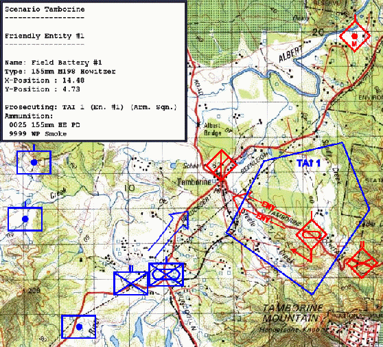
The Weapons Effects Predictor produces as an output to the user a measurement of the effects produced upon each target. This calculation is performed as follows. The numbers of rounds of each type fired at each target in each TAI is totalled. For example, if two Indirect Weapons Fire Systems fire 25 155-mm HE rounds with PD fuses at an Armoured Squadron in TAI 1 then only the total number of 50 155-mm HE PD rounds is relevant. The number of rounds required to suppress, neutralise and destroy the Armoured Squadron is known. For example, from Table 2 an Armoured Squadron can be suppressed with 100 155-mm HE rounds. Then, we say that the target is (50/100) * 100 = 50% suppressed. Now suppose that a third weapon system fires 90 155-mm DPICM rounds at the Targeted Area of Interest. Then, the target is further suppressed by (90/40) * 100 = 225% to a total of 275%. Values above 100% demonstrate excessive ammunition expenditure but, for the purpose of calculating effects, have no interpretation other than the desired effect is achieved. This example only makes reference to a single type of weapon system (a 155-mm system), a single type of target (an Armoured Squadron) and a single type of effect (suppression). However, this example is constructed without loss of generality. The calculations we use extend to all Indirect Fire Weapon Systems and target types in the study, provided the respective tables for ammunition effects are known. That is, it is just as easy to calculate the effects of arbitrary mixes of Naval Gunfire Support, Offensive Air Support, Mortar, Multiple Launch Rocket Systems, and Artillery, as it is to calculate the effects of 155-mm artillery in our example.
The calculations of effects performed above simplistically assume that the Armoured Squadron is successfully detected, recognised and identified by, for example, a Forward Observer assigned to TAI 1. We now propose to take into account the ability of the blue-force to perform ISTAR operations in the named TAI. We assert that a TAI of sufficiently large area is impossible to monitor in any practical way. That is, it may be possible to destroy any target detected in such a TAI but be impossible to locate any targets. We propose a practical, if somewhat simplistic, solution for a prediction of this nature. Each target t is assigned a weight w(t) between zero and one. This value models the perceived comparative likelihood of detecting target t. For example, it is easier to detect an Armoured Squadron than it is to detect an Armoured Platoon. This value is treated as a scaling factor and is not necessarily the same for identical enemy units in all TAIs. Each TAI i is assigned a coverage c(i) in square metres between 0 and its area a(i). This value models the blue-forces ability to conduct ISTAR operations simultaneously over TAI i. Then, the probability p(t,i) of target t being successfully detected, recognised and identified in TAI i is:
. (1)
Let s(t) be the percentage values calculated above for suppression of target t, where scores above 100% are reduced to 100%. Hence, the expected values of the effects produced on target t are:
(2)
For example, let a(TAI 1) = 1 000 000m2, c(TAI 1) = 500 000 m2 and w(Armoured Squadron) = 0.8. Then, performing the prediction of effects described above, we obtain E[Arm. Sqn is suppressed] = 0.4 * (min {100, 275}) = 40%. Similar calculations yield prediction of effects for neutralisation and destruction. These values reflect the probability that, knowing or suspecting that an Armoured Squadron is in TAI 1, the blue-force is able to fulfil the original intent of either suppressing, neutralising or destroying the unit.
We now discuss not the calculation or prediction of effects on the battlefield but the way in which Indirect Fire Weapons Systems are allocated targets. Suppose we wish to know how best to allocate a number of weapon systems with a fixed supply of rounds of known types to a number of TAIs and then to plan for the engagement of a number of enemy targets with a desired intent of either suppressing, neutralising or destroying the targets in these TAIs. For this purpose we employ Quinone [12], a modelling tool build upon Simkit [15]. Quinone was specifically designed to study the effects of allocating weapon systems and sensors to TAIs under varying forms of combat service support. We do not make use of the extended abilities of Quinone to model logistics beyond setting the number of rounds available to each weapon system. However, Quinone is perfect for the simulation of simple effects and the study of different arrangements of weapons systems. Hence, we link Quinone to the Weapons Effects Predictor to exploit Quinone’s modelling abilities and the Weapons Effects Predictors calculation and prediction algorithms. This synergy works as follows. The Weapons Effects Predictor provides Quinone with a number of alternative automatically generated allocations for the Indirect Fire Weapons Systems to the TAIs and the targets in the TAIs. Currently, this generation is performed by complete enumeration. It is acknowledged that this is not a scalable approach. Future revisions of the software will address this issue. Next, for each of these allocations Quinone runs a number of Monte Carlo simulations, using the Weapons Effects Predictor to calculate effects, and returns averaged values for the actual suppress, neutralise and destroy percentages obtained over the Monte Carlo simulations for each target in each TAI. A list of these results over all alternative allocations is logged into a file, one allocation per row. For example, the row entry
(1:1) (2:1) (3:1) ~ [1=56,37,11] [2=0,0,0],
is interpreted as weapon systems 1, 2, and 3 assigned to target 1 giving the suppression, neutralisation and destruction scores of 56%, 37%, and 11% respectively for target 1 and 0% on all counts for target 2. The type of weapons systems and targets associated with the numbers 1 through 3 and 1 through 2 respectively are identified within the Weapons Effects Predictor. In this example, the log file contains 8 rows, one for each possible combination of three weapons systems to two targets. The outputs of these simulations are interpreted as a stochastic prediction or estimation of the likely effects produced on targets. The Monte Carlo sampling and the averaging of results over a number of simulations provide users with empirical expectations for the effects produced.
Conclusions
The software developed in this study is both flexible and extendable. For example, the Weapons Effects Predictor and Quinone may be replaced with other alternative tools offering enhanced realism or greater fidelity models. Furthermore, it is possible to extend the study to include, for example, the effects produced by armed reconnaissance helicopters and direct-fire platforms such as tanks. Potentially, the scope of the tool could be increased to include realistic terrain and ballistics models. With such additions, areas on the map that are obscured from the weapons systems by terrain such as hills or valleys could be identified and shaded. Also, the user could be alerted to weapons effects produced in proximity to friendly or civilian forces.
We have presented a simple and practical framework for the definition of weapons effects prediction. This study contains no meta-metrics for optimisation but merely performs calculations based on factual data obtained from Army doctrine. The software does not judge any results produced but collates and presents them to a user. Hence, the user has complete control over any and all decisions made. The tool is not designed to replace humans planning field operations. However, the tool has a potential to assist and facilitate the user in this task.
Acknowledgements
The assistance of Alex Ryan at the Defence Science and Technology Organisation and MAJ Alistair Dickie, MAJ Brendon Sammut and LTCOL Timothy Pickford of the Australian Army is gratefully acknowledged.
References
[1] Aerospace Concepts. Indirect Fire Weapons Systems Engagement Systems Study, ACPL-REPORT-22-2002-J08, Aerospace Concepts Pty Ltd, Adelaide, Australia, 2003.
[2] Australian Army. Artillery Technical Handbook, Royal Australian Artillery Corps Training Note (CTN RAA 5-30). Australian Defence Force Publication, 1992.
[3] Australian Army. Characteristics of Ordinance, Fuses and Pistols, Royal Australian Engineers Corps Training Note (CTN RAE 4-5-4), Australian Defence Force Publication, 1997.
[4] Australian Army. Combat Officers Advanced Course (COAC) Battle Book, Australian Defence Force Publication. Australia, 2001.
[5] Australian Army. Employment of Artillery, Manual of Land Warfare (MLW 2-1-1). Australian Defence Force Publication, Australia, 1995.
[6] Australian Army. Gun Drill Howitzer Pack 105mm L5, Royal Australian Artillery, Corps Training Note (CTN RAA 5-12). Australian Defence Force Publication, 2000.
[7] Australian Army. Gun Regiments—Duties in Action, Royal Australian Artillery Corps Training Note (CTN RAA 3-2). Australian Defence Force Publication, 1989.
[8] Australian Army. JOST Course Study Notes, Australian Defence Force Publication, 2001.
[9] Australian Army. Gun Drill M198 155mm Towed Howitzer, Royal Australian Artillery Corps Training Note (CTN RAA 5-14). Australian Defence Force Publication, 1997
[10] Australian Army. Mortar 81mm F2 Firing Tables, Land Warfare Procedures—Combat Arms (Offensive Support) (LWP-CA (0S) 5-2-5), Australian Defence Force Publication, 2001.
[11] Australian Army. Mortar 81mm F2 Tactical Employment and Fire Control, Manual of Land Warfare, Part 2 Infantry Training (MLW 2-5-2), Australian Defence Force Publication, 1980.
[12] A. Dickie, G. Martin, D. Buchanan, P. Barry, A. Buss, K. Grau, S. Ho, and T. Ming. Networked Offensive Fires, Team 7 Report, Project Albert International Workshop 8, Singapore, April 2004.
[13] Jane’s. Jane’s Online, viewed 1st September 2004, <www.janes.com>
[14] OpenMap homepage, BBN Technologies, viewed 1st September 2004, <http://openmap.bbn.com/>
[15] Simkit homepage, United States Naval Postgraduate School Monterey, viewed 1st September 2004, <http://diana.or.nps.navy.mil/Simkit/>
[16] United States Army. Operator's Manual Howitzer, Medium, Self-Propelled 155 Millimeter M109A6, Technical Manual (TM 9-2350-314-10), 1999.
[17] United States Army. Tactical Employment of Mortars, Field Manual (FM 7-90), 1992.
[18] United States Army. Tactics, Techniques and Procedures for Field Artillery Manual Cannon Gunnery, Field Manual (FM 6-40), Marine Corps Reference Publication (MCRP 3-1.6.24), 1996.
[19] United States Army. Tactics, Techniques, and Procedures for M109A6(PALADIN), Special Text (ST 6-50-60), 1993.
[20] United States Army. Tactics, Techniques, and Procedures for Multiple Launch Rocket System (MLRS) Operations, Field Manual (FM 6-60), Marine Corps Reference Publication (MCRP 3-1.6.24), 1996.
[21] United States Army. Tactics, Techniques, and Procedures for the Field Artillery Cannon Battery, Field Manual (FM 6-50), 1996.
[22] United States Joint Services. Effectiveness Data for Howitzer, 155mm M198 and M109A2/A3, Field Manual (FM 101-60-25), United States Joint and Multiservice Publication, 1994
[23] United States Joint Services. Effectiveness Data for the Multiple Launch Rocket System (MLRS): 227mm M270, Field Manual (FM 101-60-28), United States Joint and Multiservice Publication, 1994.
[24] United States Joint Services. Field Artillery Target Analysis and Weapons Employment: Nonnuclear, Field Manual (FM 6-141-1), United States Joint and Multiservice Publication, 1978.
[25] United Stated Joint Services. Lethal Area of Selected US Army, US Navy and US Marine Corps Surface-to-Surface Weapons Against Personnel and Materiel Targets, Field Manual (FM 101-62-2/1), United States Joint and Multiservice Publication, 1979.
[26] United Stated Joint Services. Safe Distances for Fragmentary Munitions, Field Manual (FM 101-62-1), United States Joint and Multiservice Publication, 1987.