
Volume 8, Number 1, March 2005
Laser Analysis—Part 3
- 1 Armaments and Air Defence Systems Project Office, Defence Material Organisation, Victoria Barracks Melbourne, Victoria 3004, Australia.
- 2 Head Electro-optics Group, DAPS, Cranfield University, Royal Military College of Science, Shrivenham, UK.
Abstract
This paper is the third in a series on laser technology. The focus is primarily the Ground Based Air Defence (GBAD) scenario but is applicable to other ground, air and maritime environments. The purpose of the series is to investigate a viable technique, which may be used for the identification of GBAD Targets. Part 1 introduced and described areas of laser technology, which are commonplace on the modern battlefield. Part 2 discussed laser safety, factors effecting laser performance and Ladar. The calculations shown demonstrated Ladar’s potential as a long range (>10 km), 24-hour, all-weather imaging capability, if it is accurately cued. Part 3 examines Burst Illumination Laser (BIL), which is the chosen technique for the GBAD target identification problem. A method of calculating BIL performance is shown and the results from the authors’ calculation tool are summarised.
Introduction
As discussed in Part 2, the high frequency of laser radiation provides excellent spatial resolution, which enables a sufficient number of reflections (echoes) along a target surface to build an image. The key flaws to using Ladar for identification are: (1) the requirement for precise cueing from another device before and during the ‘scanning’ process of building the image; and (2) the time required to gain an image of suitable resolution for identification.
To overcome these limitations the following scheme is proposed: if enough laser energy could be transmitted out to ranges in excess of 10 km and the energy reflected by the target was sufficiently large to be useful, then a laser beam could be used to illuminate the whole target at once and effectively take a photograph.
This is the principle of the Burst Illumination Laser (BIL) Technique, which may offer a solution to the GBAD and other battlefield identification problems.
The emerging technology of BIL is the use of a pulsed, single beam of laser radiation to illuminate the target and reception of the reflected energy for analysis and viewing. The detector is gated to the target’s range vicinity to eliminate unwanted noise (predominately atmospheric scatter); a gated receiver bandwidth, encompassing the transmitted laser frequency, is used to eliminate other light sources. The concept has been demonstrated in a favourable environment against maritime targets. [1]
BIL technology is available for shorter-range applications. [2] The technique offers a number of advantages that make it a viable option for target identification. [3,4] They are:
- High spatial resolution.
- Not susceptible to sun glint.
- Not susceptible to scatter from haze or aerosols.
- Short illumination requirement for reduced blurring.
- Video like imagery.
- More eye safe frequency.
- ‘Snap shot’ imagery without a scan period or extensive processing (compared to Ladar).
This paper presents the authors’ calculations that prove in theory that BIL is a viable technique for identifying GBAD or battlefield targets beyond the ranges of short-range air-defence (SHORAD) weapons (>10km).
Accounting for noise and attenuation
Signal-to-noise ratio (SNR) is the ratio of the signal that the detector receives and unwanted noise from internal or external sources. Often for initial calculations, it is acceptable to take a pessimistic value for SNR, such as 10. However, for this application, the primary source of noise is unwanted returns from the atmosphere between the transmitter and the target, which will vary greatly with range. A more accurate prediction, which may be calculated dynamically with range, is used [5]:
| PL | Laser Peak Power | Watts |
|---|---|---|
| ηB | Energy Fraction in FOV | |
| r | Target reflectance | |
| k | Atmospheric Extinction | 1/km |
| R | Range | m |
| αm | Mass extinction coefficient for obscurant | g/m2 |
| CL | concentration/length of obscurant | g/m2 |
| NEI | Receiver noise equivalent irradiance | W/m2 |
Parameters relating to the laser and detector are usually available from the manufacturer. Atmospheric factors are available from meteorological web sites or texts or can be calculated using any number of software tools.
The effect of obscurants in the battlefield may be incorporated through the Mass Extinction Coefficient (αm). For example: if humidity is 50% and the laser wavelength (λ) is 1.574 µm, then realistic αm values would be: 0.57 for white phosphorus or smoke, 1.65 for oil or diesel fog and 0.26 for dust. [5]
The effects of water particles will be accounted for in the calculation of atmospheric transmission (ta) in later range and power calculations. A simple method of calculating ta is using Beer’s Law:
Where R is the range to target and αa is the atmospheric extinction coefficient found from tables or using programs such as MODTRAN4, HITRAN or EOSEAL.
Viewing optics and illumination source
To achieve maximum resolution, the lens system should be designed so that the target occupies as much of the viewing area as possible without being clipped. To achieve the most efficient use of the illuminating energy, the area of the scene being viewed should also be matched to the cross-sectional area of the illuminating laser beam. The length of the viewing area (LV) is a function of the detector length (LD) and focal length (f) as shown in Figure 1. Note: range (R) is approximately 10 km and the focal length (f) will be less than 1m.
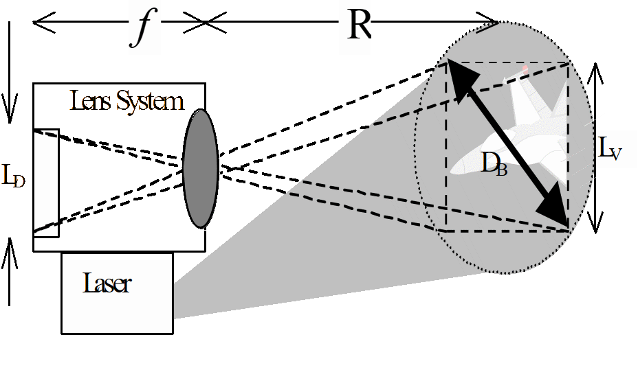
Unless clipped by the lens, the viewing area will be the shape of the detector. The Energy Fraction in the FOV (ηB) may be calculated as:
If the lens system is optimised as depicted in Figure 1, then the diameter of the beam (DB) becomes the diagonal of the square viewing area. In which case:
The 63.7% of the beam’s total energy in the field of view provides the optimal power density. Exceeding this figure by too much will result in fading of the extremities—a spot-light effect. In fact, the inner 63% of total beam energy is gated by the 1/e (relative intensity) intersection with a Gaussian plot. The 1/e intersection points are also known as the Peak Intensity points, which define beam divergence for safety calculations, see Figure 2.
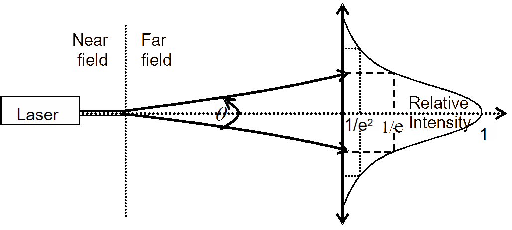
Even in a vacuum, a laser beam will naturally diverge after a certain distance. There is a region for which the edges of the beam remain close to parallel; the Near Field, before diverging at an angle (θ) into the Far Field.
The range of the near field is dependent on the laser wavelength (λ) and the diameter of the transmitting lens (d). Generally, the near field only extends for a few meters, so is of little value to this application. The beam angle and the diameter of the beam can thus be approximated, for this application, as follows: [6]
Calculating power for illumination purposes
The initial design for a Burst Illumination Laser requires certification that the reflected laser radiation (echo) from the target is of sufficient power to be detectable above the noise. It is difficult to calculate the complete target surface area (AT) that will be reflecting energy back to the collecting lens, a reasonable approximation is therefore to take a known length (LT), such as the wing span or fuselage length, square it and then multiply by 2/3. This rough approximation takes into account that a typical fighter jet has a low wing-aspect ratio with under-wing components (fuel tanks, bombs, missiles, and so on) and a bulky fuselage with a large tail section, resulting in many direct, diffuse and secondary reflections.
The total power reflected by the target surface (PT) will be a fraction of the total power transmitted (P) in the beam area (AB) dependent on the target area (AT). It will also depend on the target’s surface reflectivity coefficient (r) discussed later.
Assuming an isotropic, hemispherical reflection (the power from the targets surface is equally reflected over a solid angle of 2π steradians). Furthermore, the target surface may also be regarded as a Lambertian Surface, in that the reflected power in any given direction is proportional to the cosine of the angle between the normal to the target surface and the given direction. [5] Hence, a pessimistic approach is to divide the above PT by 2π (instead of π) due to the uncertainty of the Lambertian properties and the degree of specular reflection. Then to calculate the collected power (PCL), multiply by the solid angle subtended by the collector lens:
So that the signal is detectable, PCL must be greater than the detector’s Noise Equivalent Power (NEP) for a given SNR: that is, PCL > NEP×SNR. Using this relationship, simplifying to remove area terms and then solving for R gives:
Where NDE is the number of detector elements over which the returned power falls.
Target analysis
It can be seen from Equation 6 onwards, that the target’s length (subsequent reflecting surface area) and surface reflectivity will affect range performance. Dimensions are readily available from various open-source publications and overall reflectivity coefficient can be approximated with a limited knowledge of construction materials and coatings used on the aircraft.
The overall emissivity coefficient of the F/A-18 in Figure 3 is calculated as 0.29. Using Kirchhoff’s Law (reflectivity + emissivity = 1), r = 0.71, neglecting other surface coatings
![Surface map of F/A-18 [7] and Emissivity Values [8].](/journals/journal-of-battlefield-technology/volume-08/issue-01/assets/8-1-5-kellaway/figures/figure03.gif)
Calculation tool
Considering the simple relationships used to derive some parameters from manufacturers specifications, it can be seen that the initial design and optimisation of a BIL system from fundamental principles, requires a calculation tool. The authors’ tool [9] comprises the following tables:
- Lens System. Allows for the input of physical dimensions of the optical system. This table may be used to optimise the laser beam profile and lens system for a likely target size and range, the resultant resolution is then calculated for a variety of ranges.
- SNR and Range. Allows for the selection of atmospheric conditions, input of detector values and laser transmission values, so that SNR and range can be calculated.
- Reflectivity Calculator. If the types of material or paints on the aircraft or battlefield object are known, then they may be selected and an averaging table is used to calculate an overall target reflectivity value.
- Atmospheric Data. This look-up table is used by the SNR and Range sheet to acquire atmospheric and obscurant extinction coefficients. During iterations of the calculation, an atmospheric condition or obscurant may be selected by description. For obscurants, the affected distance along the laser’s path may be specified, such as smoke for 1 km.
Results
The results prove that in theory, a Burst Illumination Laser system optimised to 10 km is capable of GBAD target identification at ranges of:
- 20–30 km for excellent atmospheric conditions,
- 15–20 km for good atmospheric conditions,
- 7–15 km for average atmospheric conditions,
- 4–8 km for poor atmospheric conditions, and
- a few hundred metres beyond visual range for extreme conditions.
In the presence of battlefield obscurants along the line-of-sight between the BIL system and the target, range performance dropped to approximately 60–70% of those stated.
These results concur with other reports that the BIL technique can provide up to seven times the ID range of LWIR viewers and three times the range of the best MWIR viewers. [4]
System characteristics
The system parameters used to achieve the above results are shown below:
- Optimised range. For the physical design of the lens system, an ID range of 10 km was selected. This was based on estimates for decision and engagement and missile fly out periods. Once the physical parameters for the lens system are set, R must change dynamically within all other equations that contain R, to ensure accuracy in SNR, atmospheric attenuation, resolution and ultimately, actual performance range.
- Laser. A Nd:YAG laser (1.06-µm) wavelength shifted by the use of an appropriate optical parametric oscillator (OPO) to 1.574 µm is chosen for a number of reasons:
- Improved eye safety (see Part 2 of this series);
- A matched detector will be of a detection band width to provide passive low light level capabilities;
- Good spatial resolution, especially when compared to MWIR and LWIR detectors;
- Already available from a number of manufacturers in a variety of rugged and powerful configurations.
- Pulse width. A short pulse width of 10 nsec is narrow enough to eliminate the blurring from illumination platform jitter or dithering from atmospheric effects, which have been observed at 20 nsec. [1] As the pulse width is directly related to the peak power, a subsequent 20% improvement in range can be gained with a pulse width of 5 nsec. However, this would be considered the current limit for sustained operation of an Nd:YAG laser with a PRF providing video-like imagery (>15 Hz).
- Detector array. An InGaAs CCD staring array is matched to the laser frequency. A 256×256 array size is chosen, as a 128×128 array does not achieve the resolution requirements and a 512×512 array requires an impractical focal length and considerably reduces range as per NDE in Equation (9).
- Focal length. Following a series of iterations, 970 mm was found to provide good performance below the performance imposed maximum of a practical 1m.
- Collector lens diameter. 300 mm is considered to be the maximum lens size for engineering feasibility. A significant drop off in range was observed as lens size was decreased below 200 mm.
- NEP. For the same range performance, detector sensitivity is inversely proportional to laser power, which must be kept within safety limits. 1 pW achieved good results and is well above the current industry minimum of 0.1 pW and well below 100 pW, which demands unsafe laser power.
- NEI. Averaging the performance figures for a selection of other long-range, sensitive, EO systems, a constant of 1.43Δ10-9 W.m-2 was applied.
Modelling accuracy and further research
Within the model developed for this study, the illumination beam has been assumed as Gaussian, but the returned power across the detector surface has been assumed as uniform. Future research would require more realistic beam profiles and returned power distribution. Although this would not affect detection range (other than a possible increase at the centre), the identification range may be affected if the target is cropped.
NEI, which is a critical factor in the SNR equation, has not been calculated. Rather, a reasonable value has been taken as a constant. Within future research, an accurate method of calculating NEI will be determined so that the SNR is more accurate.
Atmospheric attenuation for the 1.574 µm will be calculated for future research using known conditions and a higher resolution calculation tool.
Laser and target surface interaction requires analysis beyond a calculated reflectivity factor. Considering the variety of surface coatings and their angles, values for an actual aircraft body will be measured in future research.
Proof of concept
A proven BIL system is the test bed built by Intevac, Inc USA. Initial trials have proven that it is capable of providing imagery suitable for ID at a range of 7.7 km in favourable atmospheric conditions. [2] It has been predicted that as the technique and technology improves, the range could extend beyond 20 km [3], which concurs with the findings of this study.
Conclusion
The advent of extremely sensitive detectors has allowed shorter wavelength lasers (providing suitable spatial resolution) to be used for long-range illumination purposes without being hazardous to the eye. Using pessimistic values for a comprehensive list of BIL calculation parameters, it has been proven in theory, that the technique is a feasible method of gaining imagery for the identification of likely targets beyond the range of SHORAD weapon systems for a variety of atmospheric conditions.
Being an active system, BIL is not inherently dependent on the target’s thermal or visual signature and is capable of 24-hour, limited all-weather performance beyond any passive system, if correctly optimised. Furthermore, because the range to the target can be found, the detector can be gated to provide a much higher quality image by eliminating any reflections not within the direct vicinity of the target.
The next stage of research into BIL, for this purpose, is to build a test bed that is optimised for the SHORAD target ID task. At first this would be used to prove the ID range against static targets in a variety of atmospheric conditions. The next stage would then be to determine a method of cueing the BIL system and real-time target tracking.
If the test bed proves that the ID ranges calculated in this study are approximately correct and if a method can be established of obtaining and retaining a fast target in the field of view, then BIL technology is the potential answer to the GBAD target identification problem.
References
[1] Analysis of Maratime Burst Illumination Laser trial and Recommendations for Future Research, D.C. Manson, QinetiQ UK, Feb 2003, File No: QINETIQ/FST/ TWP031279/1.0. Restricted QinetiQ in Confidence
[2] Laser Illuminated Visualisation and Ranging (LIVAR), Intevac Corporation, Santa Clara, CA 95054 URL: www.intevac.com
[3] S. Anderson, “Active Night Vision System Captures Near-IR Images”, Laser Focus World, May 1996, Vol. 32 No. 5.
[4] V. Aebi and P. Vallianos, “Laser-illuminated Viewing Provides Long-range Detail”, Laser Focus World, September 2000, URL: www.optoelectronics-world.com.
[5] Active Electro-Optical Systems, C.S. Fox (ed), Vol 6 of The Infrared and Electro-Optical Systems Handbook, published by Spie Press, 1993.
[6] Surveillance & Target Acquisition Systems, 2nd Ed, Brassey’s New Battlefield Weapon Systems and Technology Series, Vol 4, London – Washington, 1997.
[7] R. Heslehurst, Introduction to Aerospace Design, Department of Aerospace and Mechanical Engineering, ADFA, Canberra, 1995.
[8] C. Rogers and Y. Mayhew, Engineering Thermo-Dynamics Work and Heat Transfer, Longmans, Green and Co Ltd, UK, 1967.
[9] BIL_Calc Tablev2, available through the authors by e-mail.