
Volume 8, Number 1, March 2005
Synthesis Of The Lever Arm In A Gun Positioning System
- 1 Department of Mechanical Engineering, IIT Madras, Chennai-600036, India. (*Currently at Universiti Malaysia Sabah, Kota Kinabalu).
- 2 Combat Vehicle Research Development Establishment, Avadi, Chennai-600052, India.
Abstract
This paper presents the synthesis of the lever arm of a gun positioning system in main battle tank (MBT). The main gun in any MBT is controlled by a gun positioning system (GPS). Most of the contemporary MBTs use a hydraulic actuator as a drive for elevation/depression of the main gun. The Gun Positioning System (GPS) can be idealized as a four-bar mechanism. The position of the actuator mounting decides the link dimensions and hence the variation of force during elevation and depression. Since the gun position varies from 20 (elevation) to 9 (depression) for the case under consideration, the force required to move the gun varies during elevation and depression due to change of length in the links of the mechanism. In order to improve the system performance it is essential to minimize the variation in the input force with respect to the gun position. The problem has been solved using analytical method and with a virtual prototyping approach. The results obtained are compared between the two methods. The virtual prototyping approach provides effective solution with 3D visualization and hence can be pursued.
Introduction
In this paper an attempt has been made to adopt the technologies of CAD/CAE/VR/VP [1] in the design and development of GPS of an MBT. The integration of computing and graphics technologies is now called Visual Computing. Whether it is the design of an automobile or a heavy vehicle building up of a 1:1 physical mock up was essential in the early phase of design. This has now been replaced by a Digital Mockup (or) Digital Prototype Assembly (DPA), using Virtual Prototype (VP) methods for studying the adequacy of the design, collision detection at the time of assembly and easiness in maintenance.
The current design methods make simplifications and compartmentalization of a large problem into small bits. Virtual Prototyping method can model and produce the realistic picture of the functioning of entire system. The designer can visualize its 3D-motion with friction at the joints, find the interference among the components, and the influence of deformation of various members analogous to its functioning in a real life situation.
Two important aspects in the design of a mechanism are (i) obtaining the desired output motion for an input motion (ii) force transmission from input to output links with the desired mechanical advantage. In the GPS, the position of the actuator mounting decides the variation of force during elevation and depression. In an existing design the gun elevates to 20° and depresses to 9°, the force required for tilting the gun during elevation and depression is found to be in the ratio of 3:2. The pressure variation in the hydraulic power pack is also in the same order. The reduction in variation of this force will ensure uniformity in the piston travel and in the gun rotation during elevation and depression. The aim of the present work is to identify link lengths, which can give the uniform forces during elevation and depression.
GPS for a main battle tank
The two important modules in any MBT Weapon Control System (WCS) are the Gun Control System (GCS) and the Fire Control System (FCS). To have the highest hit probability an MBT requires an effective WCS. The function of the main gun system in an MBT is to fight ground targets. To engage a target, it is required to lay the gun with respect to two planes, namely elevation and azimuth. The azimuth plane is parallel to the ground surface and the elevation plane is orthogonal to the ground surface. The main gun is mounted on a structure, which can impart motion to it in the elevation plane. This will result in elevation/depression of the gun. The gun along with the mounting structure is fitted on a platform known as turret, which can rotate about the azimuth plane. This motion is known as traverse. By the combined operation of elevation and traverse, the gun can be made to aim in the required direction.
In most of the contemporary tanks, the main gun elevation is achieved using electro-hydraulic actuator and traverse is achieved using a gearbox. Since hydraulic actuator is a piston actuated linkage, much care is to be taken while designing its mounting for obtaining mechanical advantage. Moreover, improper positioning can lead the actuator assembly to bind or jam.
Mounting of the main gun in the turret
Electro-hydraulic actuator used for achieving elevation and depression of the gun is a hydraulic cylinder of double acting type, with piston rods on both sides. It is a natural candidate for this application due to the large stiffness (low fluid compressibility) and fast response rates (highly pressurized fluid). Its top eye is mounted on the gun barrel and bottom eye is mounted on an elevation bracket. Linear displacement of hydraulic actuator is used to elevate or depress the main gun. This elevation actuator also relies on the leverage created by fixing it on the gun to amplify small displacements. For achieving the required elevation/ depression of the gun, elevating cylinder (top eye (TE) and bottom eye (BE)) is to be mounted at appropriate locations both on the gun barrel and turret. A mounting scheme is presented in Figure 1. The bottom eye of the cylinder is secured to the stiff mounting bracket on the turret, and the top eye is mounted onto the gun. The gun is supported on trunnion bearings and swivels about an axis perpendicular to the gun axis.
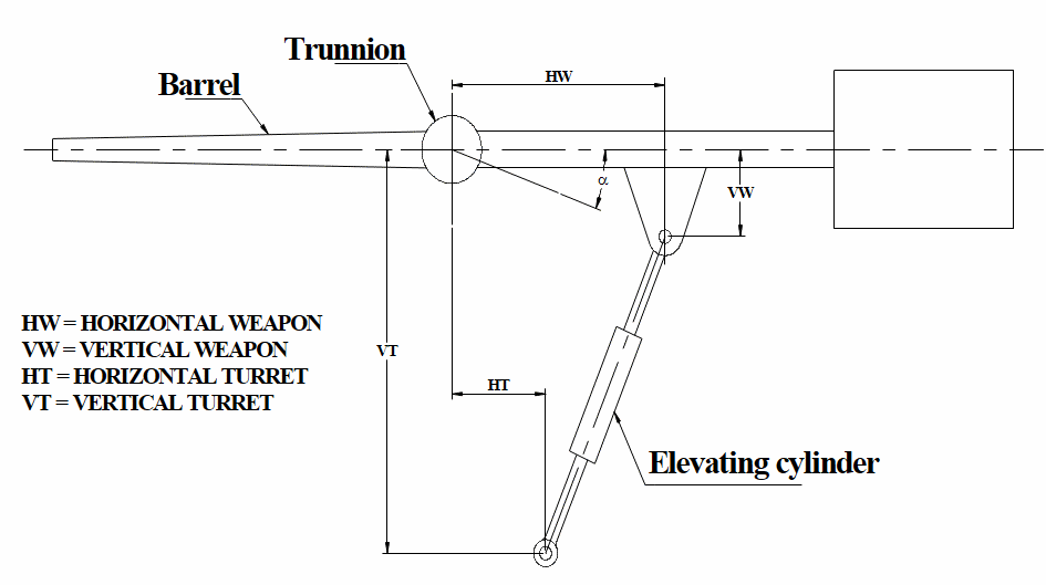
The lever arm ratio of the elevation drive is an important design parameter since the force involved here is in the order of tonnes. When the gun travels, the variation in lever arm ratio, due to the variation in the length of elevating cylinder, must be minimum in its entire angle position to maintain uniform actuator force and displacement throughout the gun travel.
The pivot location for the top eye on the gun barrel is treated as fixed point, and various locations for the bottom eye on the turret with the following constraints are considered:
- Minimum length between the top eye and bottom eye of the actuator at closed condition is 722 mm.
- Maximum length between the two eyes of the actuator at fully expanded condition is 927 mm.
- Oscillation of the gun barrel is limited to 20° upward and 9° downward.
Computation of lever arm ratio
The actuator mounting locations have to be designed for a minimum variation of lever arm ratio which in turn creates a variation in torque about the trunnion. The expressions for torque and lever arm ratio are given in Equations (1) and (2) The elevation drive can be considered as four bar mechanism with barrel, cylinder and piston are three moving links and turret as fixed link. The designs variables correspond with parameters of the lever arm ratio are, HT—Horizontal Turret; VT—Vertical Turret; HW—Horizontal Weapon; VW—Vertical Weapon.
The gun mount position for the computation of lever arm is shown in Figure 2.
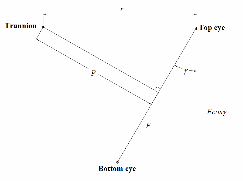
The gun is tilted about the trunnion joint due to the action of a piston force on the gun, hence, the torque is lever arm times the component of piston force normal to lever arm.
Lever arm ratio can be defined as the ratio of force along the cylinder axis to the force component normal to the line joining trunnion and top eye. Thus:
Analytical approach
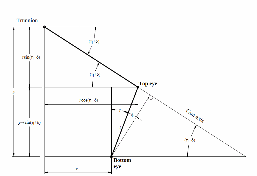
The geometrical relationship among the parameters of the elevation drive is shown in Figure 3. From the figure, the following relations can be written.
Let HT = x, VT = y; and cylinder position lp.
, , and lp is the length of line joining bottom eye and top eye. The cosine component of cylinder position :
Then:
which yields:
Lever arm ratio can be calculated from Equation (2) and Equation (6).
Extensive numerical simulations were performed, using MATLAB programming environment, to identify the configurations that could ensure acceptable variations of lever arm ratio over the entire angle of rotation.
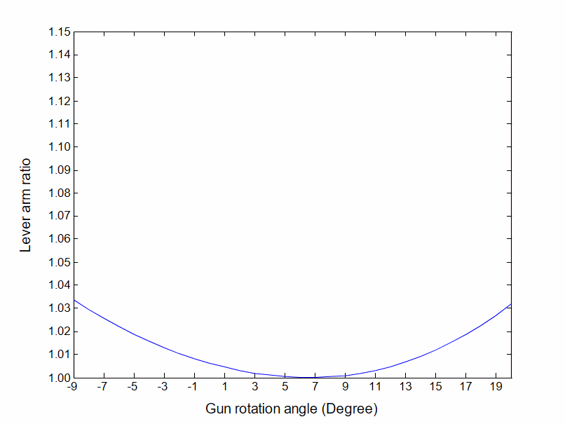
For the existing design configuration, the lever arm ratios obtained are shown in Figure 4.
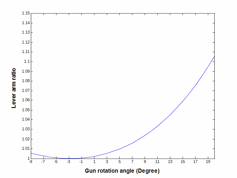
It can be seen from the figure that ratio varies from 1.006 to 1.000 while depression and from 1.000 to 1.107 while elevation of the gun with a maximum variation of 11.3%.
Parametric study
A parametric study has been carried out as a requirement in the practical design at the initial stages. Some times it may not be possible to locate the pivots in an optimal position due to space constraints. Hence, to provide information to the designer on the influence of various parameters, the following combinations have been tried to obtain a uniform lever arm ratio in the elevation and depression.
- HT increasing/decreasing
- VT increasing/decreasing
- HW increasing/decreasing
- VW increasing/decreasing
Moving either TE or BE in a curved path
- HT decreasing and VT decreasing
- HT increasing and VT increasing
- HW decreasing and VW decreasing
- HW increasing and VW increasing
Moving both TE and BE in a curved path
- HT, VT increasing and HW, VW decreasing
- HT, VT decreasing and HW, VW increasing
For the cases of HT increasing and decreasing, the lever arm ratio is shown in Figures 5 and 6. For other parameters, graphical representation has not been made for want of space; hence, the variation in the lever arm ratio for different parameters is discussed in following paragraphs.
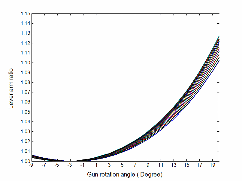
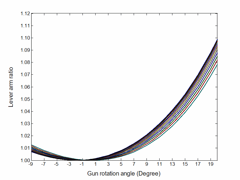
While either HT is decreasing or increasing (Figure 5 and Figure 6), that is when moving BE in a horizontal path towards or away from the trunnion, there is a trend of uniformity in the lever arm during elevation and depression. But the change is not appreciable.
From the results of the numerical simulations it is understood that while varying the design parameters individually, while moving BE and TE in a linear path, a uniform lever arm ratio during elevation and depression could not be achieved. Even though there is an appreciable change in uniformity of lever arm ratio when moving VW towards trunnion there is a practical interference with other components of the system in doing so.
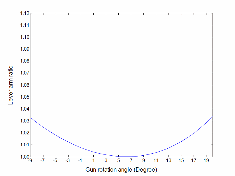
A study has been made by moving TE, BE in a curved path. While moving the TE and BE together in a curved path and when moving TE alone in a curved path there is no appreciable trend of uniformity. But when moving BE in a curved path toward trunnion, it is noted that, when HT=230 mm and VT=780 mm, the lever arm ratio is almost uniform during its entire gun rotation (elevation and depression) as shown in Figure 7.
Virtual prototyping approach
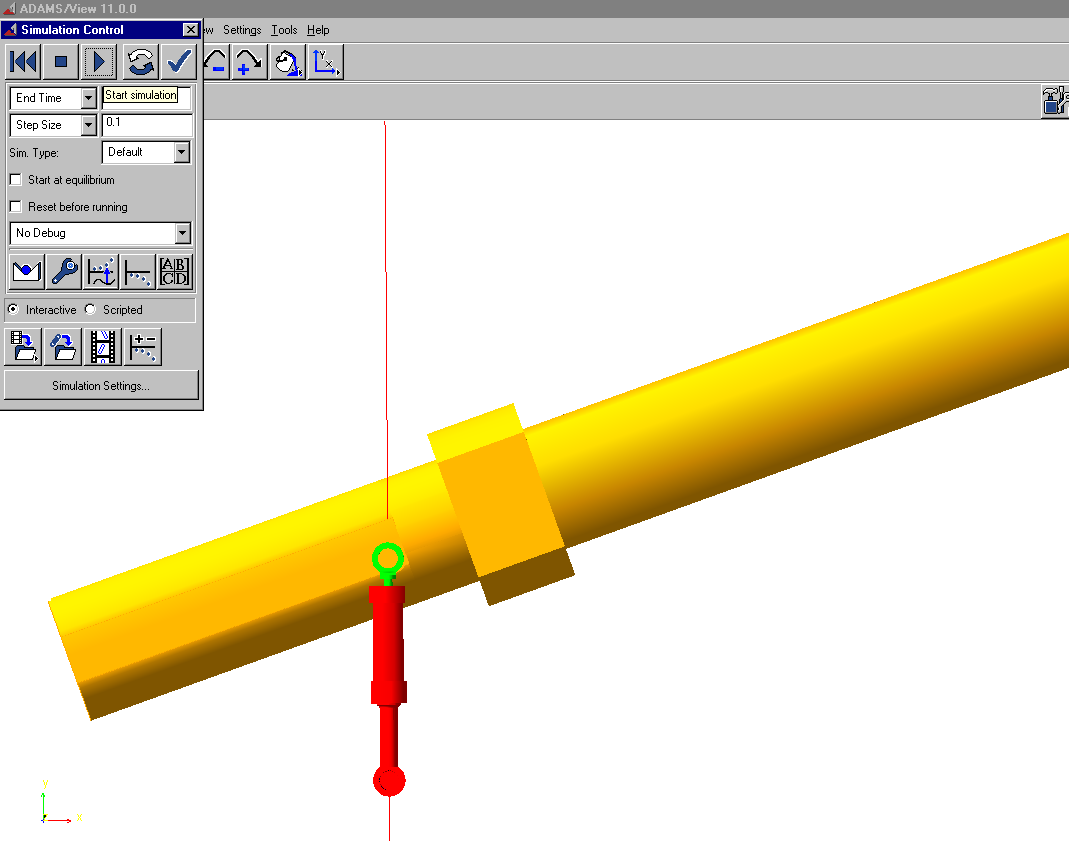
The solid models of the elevation drive components are developed in IDEAS (Integrated Design Engineering Analysis Software) and exported to ADAMS (Automatic Dynamic Analysis of Mechanical Systems—a commercially available and widely used virtual prototyping software) using IGES (Initial Graphics Exchange Specification) format. Assuming that the components in the elevation drive are rigid and the material properties are constant, the model was parameterized by only using its geometry. A solid model of the elevation drive is shown in Figure 8.
Once the ADAMS model is validated within an acceptable range, the model has been set up for a series of design studies using Design of Experiments (DOE). Design variables with a set range of values are then created for elevation cylinder mounting locations. Finally, an objective function, minimizing the lever arm ratio variation, is created. The in-built Design Optimization Tool (DOT) in ADAMS is used for getting the final configuration of the elevating cylinder mounting.
The following constraints have been applied to the virtual model:
- Cylinder stroke 205 mm.
- Elevation/Depression 20° / 9° respectively.
- Trunnion static friction torque (250 Nm).
The results obtained using VP approach is presented in Figure 9.
Conclusion
Based on the above studies the following conclusions can be drawn.
- The lever arm ratio for the existing design is not uniform in the elevation and depression. The present study shows that it can be improved by varying the design parameters.
- The analytical method and virtual prototyping method will lead to the same design parameters. Virtual prototyping methods can be used with fixed constraints. However, analytical approach provides the designer with various feasible options to fix the bottom end at the design stage depending on the constraints from other parts of the system.
This paper attempted to describe how various advances made in the area of virtual prototyping can be applied in design and development of GPS. This saves time in the design and cost involved in testing.
Acknowledgements
The authors would like express their sincere thanks to the Ministry of Human Resource and Development for supporting this research project, “Modelling and Simulation of Gun Control System”.
Authors are also thankful to Combat Vehicle Research and Development Establishment (CVRDE) for their support in this research work
References
[1] D. Purdy, An Introduction to Weapon Control Systems, RMCS, Shrivenham, SWINDON, England, SN 6 8LA, 2001.
[2] R. Ramanathan, “CAD/CAE technologies in LCA prototype Development”, Journal of Aeronautical Society of India—Special issue on Indian LCA Technologies, Vol. 54, No. 2, pp. 167–176, 2002.
[3] D. Purdy, Modelling and Simulation of a Weapon Control System for a Main Battle Tank, RMCS Shrivenham, SWINDON, England, SN 6 8LA, 2001.
[4] D. Purdy, “On the Stabilization of Out-of-Balance Guns”, Journal of Battlefield Technology, Vol. 2, No. 3, 1999.
[5] ADAMS version 11.0, Reference manuals, MDInc., Michigan, 2002.