
Volume 8, Number 1, March 2005
Simulation Of Plate Structure Subjected To Anti-Tank Mine Blast
- 1 Engineering Systems Department, Cranfield University, The Royal Military College of Science, Shrivenham, Swindon, SN6 8LA, United Kingdom.
Abstract
A brief literature review of anti-tank mines and relevant theories is described in this paper. A numerical simulation of a single plate subjected to blast loading in the air, was developed using LS-DYNA and compared with the available experimental results. There appeared to be good correlation between the two, considering that there were many variables that could influence the results. Double-plate structure simulations with an air-filled gap subjected to mine blast were then developed. The experimental and numerical simulation results have shown that using air between the two plates has little influence on either plate (in this work, air is not restrained). The bottom plate deforms mainly due to the impact of the top plate, which deforms more than the gap between the two plates. The simulation without air may then be used as a cheaper alternative. In addition, the numerical results, using CONWEP loading, seemed to be comparable with the experimental results. This analysis has provided skills necessary for future study into the development of numerical simulations in LS-DYNA, which will be crucial for modelling more complex structures.
Introduction
It is believed that one of the most dangerous weapons in the world during the 20th century was the landmine because of its versatility and cost-effectiveness. In 1994, in a report by the US Department of State, it was estimated that there were around 60 million buried landmines around the world [2]. Buried landmines can remain active for more than 50 years after being laid [3]. Since 1975, landmines have killed or injured more than one million people [4]. The estimated number of landmines and unexploded ordnance (UXO) casualties of both military and civilian personnel is between 15 000 and 20 000 per year [5]. It was estimated that 20% of tank losses in World War II were from mines [6] and 70% in the Vietnam War [7]. Landmines can also cause disruptions to the logistic supply routes, which will prevent or delay the advance of the military on the ground. A single mine costs as little as £2 but the damage caused by a mine, could cost thousands of pounds to repair the structural damages [8]. Apart from direct costs, these mines can cause other impacts, such as to medical and environmental resources, and so on.
A mine is defined as an explosive material, normally encased, designed to (i) destroy, damage or disable vehicles, boats and aircraft, or (ii) designed to wound, kill, or otherwise incapacitate personnel [1]. It may be detonated by the action of its target, the passage of time or by controlled means. Anti-tank (AT) mines are typically larger and contain several times more explosive material than anti-personnel (AP) mines—the typical amount of explosive contained in AP blast mines is 0.003–0.25 kg, while in AT blast mines is 1.5–10 kg [1]. Hence AT mines are the most likely cause of damage to vehicles and their occupants, in comparison with AP mines. It is estimated that around 80% of the mines likely to be encountered are blast mines [9]. This paper therefore only concentrates on the effect of mine blast.
Nowadays, some UN peacekeeping forces and other humanitarian agencies are working in the vicinity of anti-vehicle mines: it is therefore very important to ensure the safety of vehicle crews. New improved protection vehicles being researched, will undoubtedly involve experimental tests, which are usually very expensive and time consuming. Numerical analysis is being introduced to reduce the number of experimental tests required and hence it could provide a more economical method of development.
The vehicle structure used in mine-blast experiments and numerical simulations may range from a simple plate structure to a real vehicle. Results from the experiments are normally classified and subsequently there is limited literature available in this area. Moreover, experiments are cost-prohibitive and previous experimental results are difficult to find and correlate because some of the parameters affecting the results might not have been well-defined. Often a simple structure such as a mild-steel plate is used for testing and validation of numerical simulation. The present work reports on the development of numerical simulation relating to damage assessment of a plate subjected to mine blast. In order to validate the model the relevant experimental results are taken from Boyd [16].
The preliminary model was based on a simple plate subjected to an exploding charge in the air. The simulation was developed in LS-DYNA software LS DYNA [21]. The modelling of the blast was implemented using blast-modelling software CONWEP [10], which is an empirically based loading model within LS-DYNA. The CONWEP blast model was developed based on Kingery and Bulmash [11] and Technical Manual TM5-855-1 [12]. The blast loading model was implemented based on the report by Randers-Pearson and Bannister [13] to reduce the process of explicitly simulating the progress of the shock wave from the high explosive through the air and its interaction with the structure. It should be noted that the loading model does not take into account any confinement or tunnel effects and should not be used for analysing such problems. The CONWEP code in LS-DYNA can be used in two cases: the first one being in the free air detonation of a spherical charge and the second case in the surface detonation of a hemispherical charge. The surface detonation is the preferred option in the case of mines buried 5–20 cm deep. However, it should be noted that in reality the depth of the burial has a significant effect on the energy released from the explosive through the ground and onto the target. Other variables such as moisture content and soil type can also affect how the energy is transferred to the structure. Those below-ground effects are not included in the CONWEP blast model.
TNT equivalent
In LS-DYNA, the keyword *LOAD_BLAST needs an input of TNT explosive charge. If the charge used is not TNT then a method to convert this charge to TNT equivalent mass is applied. Smith et al [14], have described two methods. One is to use Baker et al [15] method by using conversion factors of different explosives based on its specific energy and that of TNT. The other method is to use the two conversion factors from [12], where the choice depends on whether the peak overpressure or the impulse delivered is to be matched for the actual explosive and the TNT equivalent.
Technical Manual, TM5-855-1 [12] states that for the load to be impulsive, td/T ≤ 0.1, where T = natural period of the system, td = duration of the rectangular or triangular pulse.
The period of any structure system may be calculated using:
where:
KLM = load mass factor,
Ms = mass of structure, and
Kf = stiffness of structure.
Depending on the structure configuration, these parameters (KLM, Ms, Kf ) can be found from Tables 10-1, 10-2, and 10-3 of [12].
Shell elements
Shell elements are efficient when the thickness of the structure is much smaller than the other geometry. The target plate is modelled using Belytshko-Lin-Tsay shell element because of its computational efficiency [21]. It is based on a combined co-rotational and velocity-strain formulation. This mathematical simplification from these two kinematical assumptions give added advantage; the co-rotational portion of the formulation avoids the complexities of non-linear mechanics by embedding a coordinate system within the element and the choice of rate of deformation, in the formulation facilitates the constitutive evaluation. The Belytschko-Lin-Tsay shell element uses the Mindlin theory of plates and shells to partition the velocity of any point in the shell. More details on this theory are given in the theory manual of LS-DYNA [21].
Material models
LS-DYNA [21] uses the von Mises yield condition in an isotropic elastic-plastic material model, which is given by:
where J2 is the second stress invariant. is the yield stress, which is a function of the effective plastic strain,, and the plastic strain hardening modulus, Ep giving:
This model was used by Boyd [16] because it is probably the most cost-effective plasticity model (only one history variable is stored with this model). However, this model may lead to inaccurate shell thickness update and stress after yield. An alternative material model, namely the Johnson and Cook material model [22], may be used. It has expressed the flow stress as a function of plastic strain, plastic strain rate and temperature as follow:
where:
= effective plastic strain, and
= normalised plastic strain rate
A, B, C, and n are user-defined constants
This material model is widely used to represent materials in applications subjected to large strains, high strain rates and high temperature, such as high-velocity impact and explosive detonation.
Linear equation of state for air
For the blast to travel in air, LS-DYNA [21] defines air using a linear polynomial equation of state and is defined as:
where:
E = internal energy per initial volume
are user-defined constants
To model air:
where γ = ratio of specific heat (for example γ = 1.4)
The pressure is then given by:
where:
Dynamic relaxation
Damping may be used to find the final or initial state of the solution. Finite element software may not include damping term in the equation of motion. There are two methods to damp the solution. The first is the system damping which can be applied globally any time or on a material basis. Applying the system damping could disturb the whole system and may mislead the required results. The second is called ‘dynamic relaxation’ which is used in the beginning of the solution phase to acquire the initial stress and displacement before starting the analysis.
One can apply the dynamic relaxation factor as:
where:
= velocity at time n+1/2 and n–1/2,
a = acceleration,
η = dynamic relaxation factor, and
t = time.
The relaxation process continues until a convergence criteria based on global kinetic energy Eke (excludes any rigid body components) is met, where Eke<tol*Eke(max), (tol = convergence tolerance).
Boyd’s mine blast experiment
A 1 200-mm square, 5-mm thick mild steel plate was bolted and subjected to mine blast by Boyd [16]. There was approximately 1 000-mm square free to move under the blast load (This dimension is then used later in the simulation). The frame was positioned on four Pendine blocks. A sphere of Pentolite (explosive) weighing 250g was detonated centrally. Boyd’s conducted a series of trials intended to measure the acceleration and displacement of the plate by varying the plate to explosive stand off distances of 500, 400 and 250 mm. Each plate had five gauges pasted on it. There were two Endevco 7255A piezoelectric accelerometers (gauge A1 is at 100 mm and A2 at 200 mm from D1), two PCB Piezotronic 109A piezoelectric pressure gauges (gauge P1 is at 100 mm and P2 at 200 mm from D1), and a Novotechnik TI50 LVDT resistive displacement gauge (gauge D1 is at the centre point on the plate).
Development of numerical model and its varification
Boyd [16] developed a numerical simulation using LS-DYNA3D version 940. The blast-pressure parameters (peak overpressure, positive impulse and time of arrival) applied to the model was derived from CONWEP [10]. The pressure was applied uniformly over the plate. The plate was modelled using isotropic elastic/plastic shell elements. The relevant material properties of the target plate are given in Table 1.
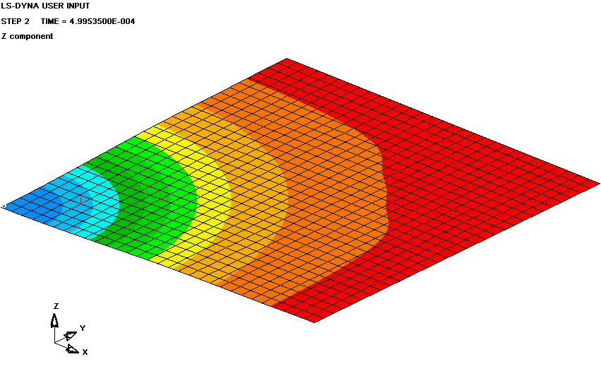
Based on the available information from Boyd [16], a similar model was created using LS-DYNA (version 960 & 970) to validate and develop better understanding of the finite element blast modelling. For verification, a model was developed using thin shell elements and isotropic elastic plastic material. As described earlier, an equivalent weight impulse factor of 1.14 was applied to convert Pentolite to TNT equivalent weight. The LOAD_BLAST card in LS-DYNA was used to generate blast loading from CONWEP. During model build up and initial analysis for fine tuning, it was ascertained that 900 elements gave good accuracy. Model symmetry was also exploited and therefore only quarter model was used. Based on the configuration of the plate, a quarter model (0.5×0.5×0.005m) has been developed as shown in Figure 1. Note that the centre of symmetry of the plate is at (0,0,0). All edges of the outer plate were fixed in all degrees of freedom. No accelerometers were pasted in the numerical simulation of Boyd [16] so, for comparison, two accelerometers as shown in Figure 1 were then added at 0.0943m and 0.1886m.
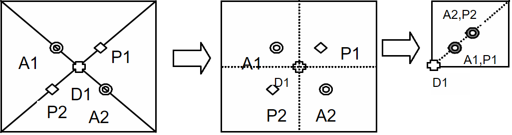
*ELEMENT_SEATBELT_ACCELEROMETER card was used to represent the accelerometers. Endevco 7255A piezoelectric accelerometer [18] weighs about 0.005 kg, this value was applied accordingly, however, the simulation did not take into account of the mounting plates. In the absence of detailed information on the pressure gauge [19], a lump mass of 0.025 kg was added to represent it. Simulation was run by modelling the explosive both above and below the target plate, for a given stand-off distance, results obtained were exactly the same. The simulation was then compared with the experiment results.
Comparison of the results
To validate the present model, results were compared with Boyd’s model and his experiments. In that peak displacement and acceleration for stand off distances of 0.25, 0.40, and 0.5m were compared and are given in Tables 2, 3 and 4.
Discussion of results
- Table 2, 3 and 4 show that there are some discrepancies between the present and Boyd’s simulation when compared with experiments. One reason is that the acceleration from Boyd’s simulation was directly recorded from the node, while this work records using accelerometer card given in the version 970, which is a recommended method for the software.
- Accelerometers are attached at the node, this nodal location was slightly different than the exact experimental location, and as a result, difference in the magnitude is quite expected especially in the case of blast loading where severity of loading is extremely high.
- Both point A1 and A2 as shown in Figure 2 have the same acceleration in the case of Boyd, it is because of the fact that uniform loading over the surface was applied in the beginning [20]. This is different from the experiment in that the pressure impacting on the plate varies, with the maximum expected at the nearest point to the explosive.
| Property | Value |
|---|---|
| Young’s modulus, E | 203 GPa |
| Poisson’s Ratio, ν | 0.3 |
| Yield Stress, σy | 270 MPa |
| Tangent modulus, ET | 470 MPa |
| Density, ρ | 7850 kg/m3 |
| Hardening parameter, β | 1.0 |
| Peak displacement (mm) | Peak acceleration (g) at point A1 (100-mm from the corner) | Peak acceleration (g) at point A2 (200 mm from the corner) | |
|---|---|---|---|
| Experiment | –35 | 40 969 | 30 049 |
| Boyd’s simulation | –74 | 67 100 | 56 000 |
| Present work | –28 | 61 029 | 39 664 |
| Peak displacement (mm) | Peak acceleration (g) at point A1 (100 mm from the corner) | Peak acceleration (g) at point A2 (200 mm from the corner) | |
|---|---|---|---|
| Experiment | –36 | 17 529 | 15 052 |
| Boyd’s simulation | –44 | 30 185 | 30 185 |
| Present work | –29 | 15 219 | 21 151 |
| Peak displacement (mm) | Peak acceleration (g) at point A1 (100 mm from the corner) | Peak acceleration (g) at point A2 (200 mm from the corner) | |
|---|---|---|---|
| Experiment E14 | –33 | 14657 | 14748 |
| Experiment E15 | –33 | 13185 | 14239 |
| Boyd’ simulation | –35 | 18960 | 18960 |
| Present work | –27 | 5963 | 6707 |
- The material used in both the simulations was based on static material properties of mild steel. It did not take into account the strain-rate effects, which often occur in ductile materials.
- There are many parameters that can significantly influence the experimental results. In Boyd’s experiment, it seemed that only one test on each stand-off distance was performed, except for 0.25m, which was done twice, as a result it is difficult, in scientific terms, to say how reproducible the results are.
- The exact position of the charge may vary during subsequent firing and that will result in certain differences.
- The model was developed based on the assumption that the plate was fixed in all degrees of freedom on its edges. In reality it was bolted at the edges, this will cause some discrepancies.
- Overall, the existing model shows better agreement than the Boyd model in comparison with the experimental results.
Simulation of double-plate structure
Based on the successful experiences of single-plate simulation and comparison with Boyd [16], a double-plate model was developed. Experiments to evaluate the resistive performance against a mine blast were performed by Sharples [17] for four different configuration, namely homogeneous single steel plate, spaced steel, bonded and unbonded honeycomb core sandwich configurations (an aluminium honeycomb core surrounded by steel plates). The results that are of interest are the spaced steel case (93-mm gap). 0.5 kg of PE4 was detonated in the air at stand off distances of 0.5, 0.4, 0.3, 0.2, and 0.1m from the first (top) plate as shown in Fig. 3. 500×500×6-mm target plates (BS EN 10025: S275JR) were constraint on the rig by means of bolts. The final dimensions of each plate were reduced to 495×495 mm to allow for any misalignment of the rig during assembly.
During experiments, only maximum permanent deformation was evaluated, therefore the simulation must be able to find the maximum permanent deformation. There are two methods to find the maximum permanent deformation using LSDYNA. One is to find the average value from the deformation curve and the other is to use a dynamic relaxation method. By using isotropic elastic/plastic material model it was difficult to estimate the average value from the deformation curve. Johnson and Cook [22] material model within LS-DYNA was then used to find maximum permanent deformation for both methods.
A quarter model was developed because of the model symmetry. Both plates were modelled using Lagrangian shell elements. To validate the modelling technique, firstly single plate model was developed followed by double plate with space between them. Results on single plate for different stand-off distances are given in Table 5.
Results of simulation using single plate only and comparison with experiment results
Table-5 highlights that as the stand-off distance increases, the permanent deformation reduces. This is as expected because it is logical that the further away you are from the blast, the less effect you will get.
| Stand off (m) | Maximum permanent deformation using average value from the curve (mm) | Maximum permanent deformation using dynamic relaxation method (mm) | Experiment results (mm) |
|---|---|---|---|
| 0.5 | –17.5 | –16.0 | –33 |
| 0.4 | –23.0 | –22.0 | –42 |
| 0.3 | –31.5 | –31.0 | –62 |
| 0.2 | –42.0 | –42.0 | –93 |
| 0.1 | –134.0 | –132.0 | –139 |
With the exception of 0.1-m stand off, the maximum permanent deformation from the simulation (both methods) seemed to under predict by 50% in comparison with the experiment results. Discrepancies between 20% to 40% are generally acceptable in some literature on modelling of real explosive, such as in Vulitsky et al [23]. At present, blast loading is applied using empirically derived method (CONWEP), blast loading which has been used in the simulation is based on some assumptions and estimations. It assumes that the charge was spherical in shape and need to be converted to TNT equivalent. It sometimes extrapolates the load curve in order give the load at certain distance (for example, it has only six sets of data results from the centre of the charge up to 100 mm for 1 kg of TNT spherical burst). The simulation assumed that the plate was constrained in all degrees of freedom across the boundary. The material properties of the plate were based on BS1006 steel, ideally test specimen from the plate should be test to accurately evaluate the material properties. Errors such as exact location of the charge, the position of the plate, the condition of the steel plate (how bent and rusty it is, for example), the movement of the rig and the accuracy of taking the measurements can all have significant effect on the results.
From Table 5, it can be seen that the maximum deformation from ‘average value’ and ‘dynamic relaxation’ method are very close to each other. The difference between them is no more than 1.5 mm.
Results of double plate simulation and its comparison with experimental results
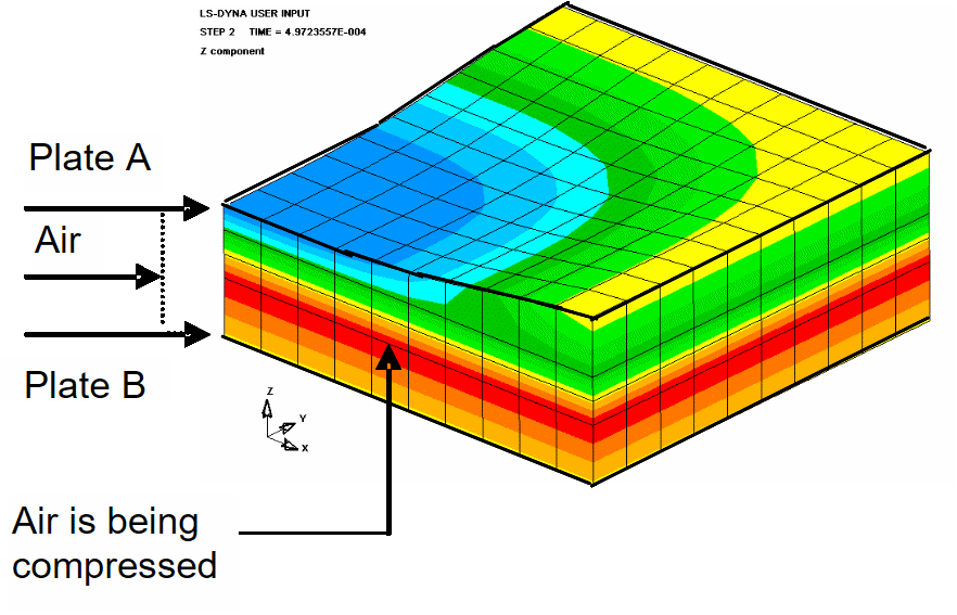
In order to model the second (bottom) plate and accurately transmit the blast load from the first plate, one must include air as a medium between the two plates as shown in Figure 7. In this case, air was modelled using solid element with Euler formulation and using a linear polynomial equation of state as described earlier. The plates were modelled using shell element with Lagrangian formulation. For stability and effective transmission of the load, the nodes at the boundary between the plates and air were merged together. Results of the maximum permanent deformation were recorded using ‘average value’ and are given in Table 6.
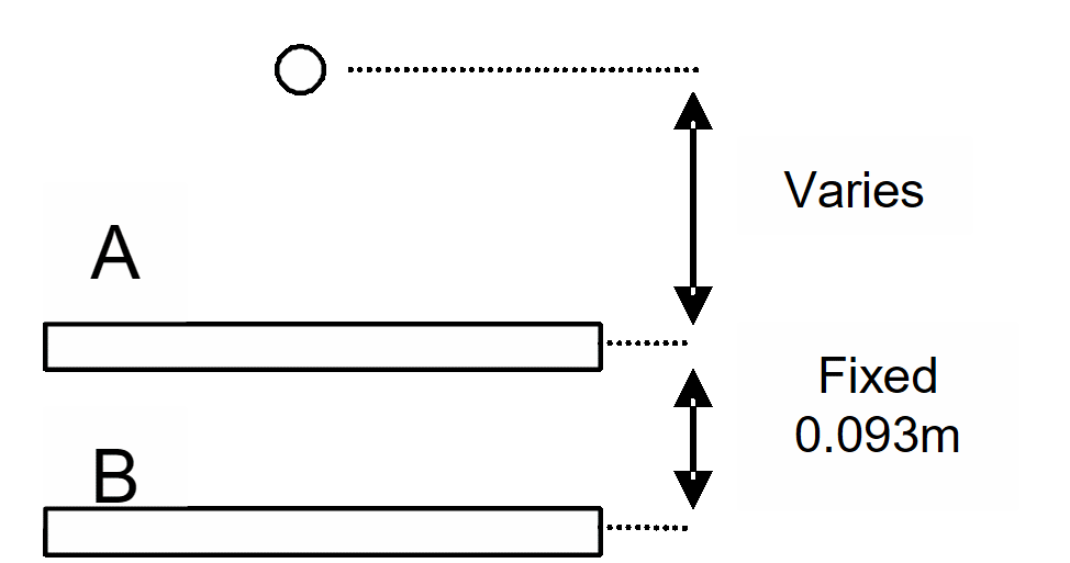
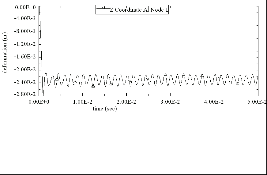
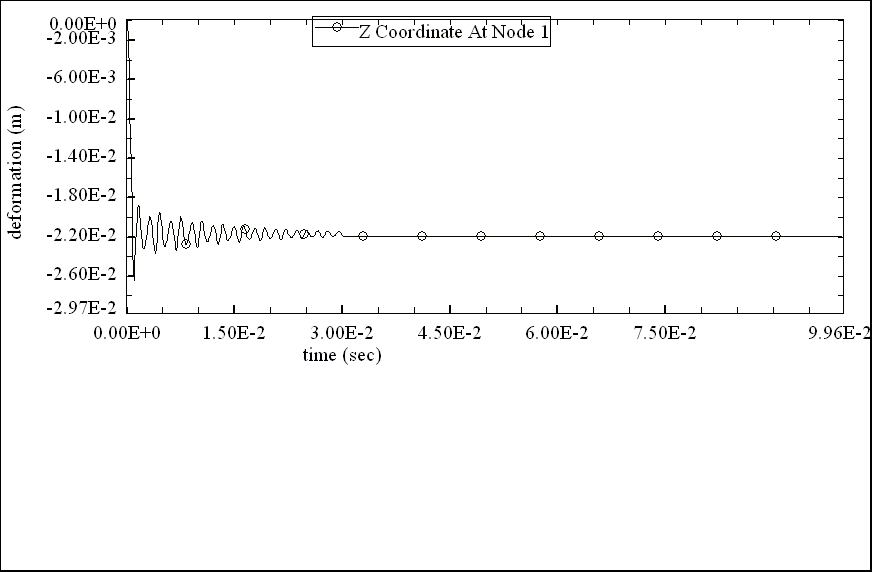
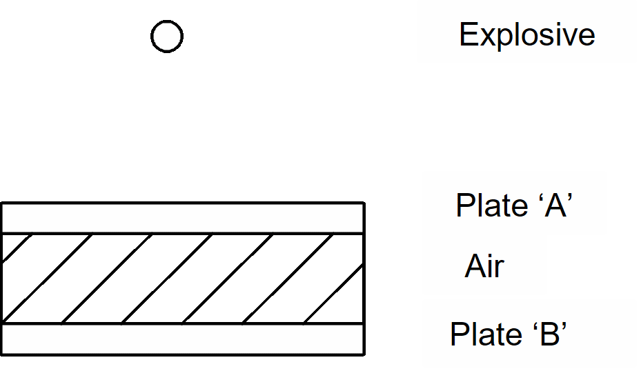
Table 6 shows that the deformation of plate A is 50% under predicted when compared with the experimental results. This result is inline with the above example and discrepancies can be argued as above. However, the deformation of plate B is in good agreement with the experimental results. The blast loading does not directly act on the bottom plate and it can be seen that the air has very little effect on its deformation.
It can be seen that at the same stand off distance, modelling with air or without air (‘1 plate only’ case) gave virtually exactly the same permanent deformation at plate A (top plate). It means that air has very small effects on the deformation of the top plate
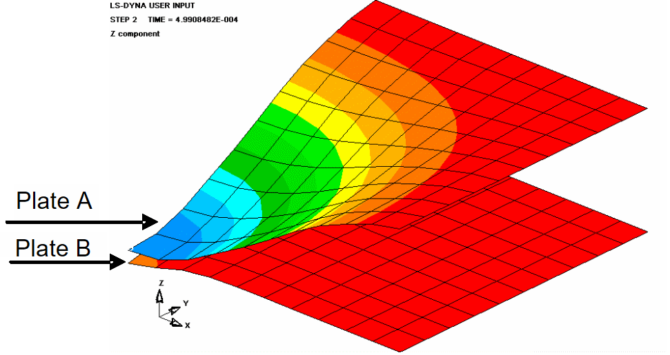
Air has successfully acted as a cushion and as a result the second plate has experienced less loading and therefore less permanent deformation. The only principal effect on the bottom plate (second) has come from the top plate which has deformed to an extent that it made a contact with the second plate and thereby forced the bottom plate to deform accordingly. Hence, modelling without air and applying the load only on the top plate can be used to simplify the simulation effectively. For example, in the case of 0.1-m stand off, the simulation can be modelled without instability error. This case can be shown in Table 7.
From Table 6, the results also demonstrate that double-plate structure significantly reduces the damage to the bottom plate (plate B). For example, if the gap between the two plates is estimated to be 0.1m (instead of 0.093 m). At stand off distance of 0.3m, the case of 1-plate only would represent the case of double plate with 0.2m stand off, where the bottom plate is 0.3m away from the charge. The result of bottom plate deformation at the double plate case was significantly reduced from 31.5 mm to just 1 mm in comparison with the one-plate only case.
| Stand off (m) | ‘Two plates with air in-between’ case (mm) | ‘One plate only’ case (mm) | Experiment results (mm) | ||
|---|---|---|---|---|---|
| Plate A (top) | Plate B (bottom) | Plate A | Plate A (top) | Plate B (bottom) | |
| 0.5 | –17.5 | –0.95 | –17.5 | –33 | 0 |
| 0.4 | –23.0 | –0.96 | –23.0 | –42 | 0 |
| 0.3 | –31.0 | –0.99 | –31.5 | –62 | –1 |
| 0.2 | –42.0 | –1.03 | –42.0 | –93 | –1 |
| 0.1 | n/a | n/a | –133.77 | –139 | –37 |
| Stand off (m) | Maximum permanent deformation at Plate A (top plate) (mm) | Maximum permanent deformation at Plate B (bottom plate) (mm) |
|---|---|---|
| 0.11 | –105 | –21.0 |
| 0.10 | –112 | –41.0 |
Conclusions
The effect of mine blast on a simple structure such as plate has been modelled using LSDYNA. The modelling technique has been verified with Boyd’s method and results are compared with his experiments. The model was used to analyse a double plate structure and to evaluate the effect on second plate which showed that a spaced structure can mitigate the effect of blast and thereby reduce the damaging effects. Although there are lots of uncertainties which can have significant effect, results have demonstrated reasonable agreement with the experiments and have also demonstrated that spaced structure with air in between will reduce the damage effect.
References
[1] C. King, Jane’s Mines and Mine Clearance, Sixth edition 2001–2002, Jane’s Information Group Limited, September 2001.
[2] The US Department of State, Hidden Killers: The Global Landmine Crisis, Bureau of Political Military Affairs, Office of Humanitarian Demining Programs, Washington DC, USA, September 1998.
[3] http://www.army.mod.uk/royalengineerings/org/mitc/index.
[4] http://www.people.howstuffworks.com/landmine.
[5] International Campaign to Ban Landmines, Landmine Monitor Report 2002: Toward a Mine-free World, 4th annual report, http://www.icbl.org/lm/2002.
[6] C. Sloan, Mine Warfare on Land, Brassey’s Defence Publishers, London, 1986.
[7] P. Ashcroft, Is There A Future For The Anti-tank Mine? Dissertation for the MA degree in military studies, Cranfield University, July 1999.
[8] http://www.landmines.org.
[9] R. Ogorkiewicz, Impact of Mines On Armoured Vehicle Design, Survivability of Light Armoured Vehicles Course, Cranfield University, Shrivenham, UK, Oct 2003.
[10] D. Hyde, CONWEP:Conventional Weapons Effects Program. US Army Waterways Experimental Station, Vicksburg, MS, USA, 1991.
[11] C. Kingery and G. Bulmash, Air-Blast Parameters from TNT Spherical Air Burst and Hemispherical Surface Burst, ARBRL-TR-02555, U.S. Army Ballistic Research Laboratory, Aberdeen Proving Ground, MD, April 1984.
[12] Fundamentals Of Protective Design For Conventional Weapons. Technical manual TM5-855-1, US Department of the Army, 1985.
[13] G. Randers-Pehrson and K. Bannister, Airblast Loading Model For DYNA2D and DYNA3D. ARL-TR-1310, Army Research Laboratory, Aberdeen Proving Ground, MD, 1997.
[14] P. Smith and J. Hetherington, Blast And Ballistic Loading Of Structures, Butterworth-Heinemann Ltd, Great Britain, 1994.
[15] W. Baker, P. Cox, P. Westine, J. Kulesz, and R. Strehlow, Explosion Hazards and Evaluation, Elsevier, Amsterdam, 1983.
[16] S. Boyd, Acceleration Of A Plate Subjected To Explosive Blast Loading-trial Results, DSTO-TN-0270, Defence Science and Technology Organisation, 2000.
[17] N. Sharples, Resistance Of Homogeneous, Spaced And Honeycomb Core Sandwich Panels To Explosive Blast, MSc Project Report, Cranfield University (RMCS Shrivenham), Swindon UK, July 2002.
[18] http://www.process-controls.com.
[19] http//www.pcb.com.
[20] S. Boyd, private communication, 2004.
[21] J. Hallquist, LS-DYNA Theoretical Manual v970, Livermore Software Technology Corporation, May 1998.
[22] G. Johnson and W. Cook, “A Constitutive Model And Data For Metals Subjected To Large Strains, High Strain Rates And High Temperatures”, 7th International Symposium on Ballistics, Hague, Netherlands, April 1983.
[23] M. Vulitsky and Z. Karni, “Ship Structures Subject To High Explosive Detonation”, 7th International LS-DYNA Users Conference, 2002.