
Volume 7, Number 3, November 2004
Laser Analysis—Part 2
- 1 Armaments Systems Project Office, Defence Material Organisation, Victoria Barracks Melbourne, Victoria 3004, Australia.
- 2 Head Electro-optics Group, DAPS, Cranfield University, Royal Military College of Science, Shrivenham, UK.
Abstract
This paper is the second in a series of three on laser technology. The focus of this paper is primarily the Ground Based Air Defence (GBAD) scenario but the contents are applicable to other ground, air and maritime environments. The purpose of the series is to investigate a viable technique, which may be used for the identification of GBAD targets. Part 1 introduced and described areas of laser technology, which are commonplace on the modern battlefield. This second part discusses laser safety, factors affecting laser performance and Ladar. The calculations shown demonstrate Ladar’s potential as a long range (>10 km), 24-hour all-weather imaging capability, if it is accurately cued. Part 3 will examine Burst Illumination Laser (BIL), which is the chosen technique for the GBAD target identification problem. A method of calculating BIL performance will be shown and the results from the authors’ calculation tool will be presented.
Introduction
Having established in Part 1 [1] of this series of papers the breadth of laser applications in the battlefield, it is appropriate to discuss laser safety and the factors that affect laser performance.
Then, in keeping with the aim of this series, this paper investigates by initial calculations whether LADAR could be a suitable means of providing imagery for the identification of GBAD targets.
Key laser safety design considerations
As opposed to other light sources, laser energy may be focused on a very small point on the eye’s surface, which may lead to tissue damage or blindness. Let us compare the power that could enter the pupil from a common 1-mW laser pointer to a common 60-W light globe. Both objects are held 1m from the eye—see Figure 1.
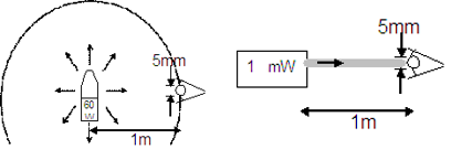
In this case, all of the laser pointer energy (110–3W) may enter the eye through the pupil, as the beam diameter is smaller than the pupil’s diameter (approximately 4–7 mm depending on ambient light conditions).
For the light globe, firstly calculate the irradiance (power density) by dividing the total power by the area over which the power is being spread (that is, the 1-m sphere):
(1)
Then the power entering the eye through the pupil is the above power density multiplied by the area of the pupil (assume a pupil diameter of 5 mm):
(2)
So it can be seen that a typical laser pointer held at the same distance as a typical light globe may impart approximately 10 times more power into the eye via the pupil.
This calculation does not take into account that 60W is the input energy of the bulb—most of which is emitted thermally. Incorporating an optimistic efficiency factor of 25% for a tungsten bulb would prove that the 15W of actual light energy emits about 40 times less power into the eye than the 1-mW laser.
Of all the laser wavebands, the visible (0.4–0.7 µm) and infrared-A (IR-A) (0.7–1.4 µm) bands are the most dangerous. They penetrate the eye’s protective layers (Figure 2) and are focused by the cornea and lens onto the retina (the retina is where the light sensitive cells are found). This focusing of the laser energy greatly increases the irradiance. The fovea is the region of the retina responsible for high visual acuity and colour vision [2]. Damage to the peripheral region of the retina can lead to blind spots which, if small enough, may not have a significant effect on the overall performance of the eye. On the other hand, damage to the fovea is usually severe, leading to the loss of high-quality colour vision with only lower-resolution peripheral vision remaining. Of course, as with any over-exposure to electromagnetic radiation, severe exposure of the retina may result in haemorrhage, which will fill the eye with blood and will most likely cause permanent and total blindness.
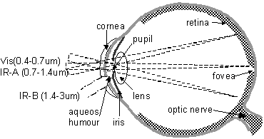
So one key laser-safety design consideration is to avoid the visible and IR-A frequency bands altogether. The energy of an IR-B laser for example, would be partly absorbed by the cornea and mostly absorbed by the aqueous humour. Overexposure could lead to burning of either but only at a much higher power level as there is no focusing of the laser beam and hence no commensurate increase in irradiance. Also, corneal damage may be operable.
The methods of calculating maximum permissible exposure (MPE) and the nominal ocular hazard distance (NOHD) are well documented and taught widely [3–5]. For military applications, the manufacturers’ guidance and the classification system are the simplest method of determining potential hazard:
- Class 1—safe under all reasonable conditions of use.
- Class 2—damage is averted by blink response, even when viewing aides such as binoculars are in use.
- Class 3A—damage is averted by blink response but not if viewing aides are in use.
- Class 3B Restricted—damage is averted by blink response AND when used in bright conditions (so the pupil is small)
- Class 3B—unsafe for eyes but should not damage skin.
- Class 4—unsafe for eyes and skin and can cause fires.
Environmental factors affecting laser performance
As with any electromagnetic transmission, there may well be a drop in intensity or changes to the beam shape due to atmospheric effects. An influencing factor on laser frequency selection is the best atmospheric transmission for a given wavelength. Lasers that are required to efficiently transmit through the atmosphere must be of a wavelength that lies in a ‘transmission window’. This is where the frequency is not as susceptible to absorption or scattering by elements such as carbon dioxide, water or smoke between the laser and the target.
Other key factors affecting laser transmission are turbulence, blooming and scintillation.
Absorption and scattering
Atmospheric absorption is the transfer of energy from the incident radiation into the atmosphere (usually to the form of thermal energy). Atmospheric scattering is the deviation in path of radiation after collision with a ‘particle’ in the atmosphere. The effect of absorption and scattering is therefore to attenuate any laser beam as it propagates through the atmosphere. Approximate sizes in µm of some particles and aerosols are shown in Table 1 [2].
| Smoke | 0.2 – 2 |
|---|---|
| Haze | up to 1 |
| Dust | 1 – 10 |
| Fog and cloud | 5 – 50 |
| Fumes | up to 100 |
| Mist | 50 – 100 |
| Drizzle | 100 – 500 |
| Rain | 500 – 5000 |
Generally aerosol scattering is the dominant factor for reducing the transmission range of visible and IR-A lasers, whereas molecular absorption is dominant in reducing the transmission range for IR-B lasers. IR-B lasers usually have better transmission through aerosols than IR-A but the advantage is lost when the particle size exceeds double the wavelength.
Because absorption and scattering are so critical to laser performance they must be accounted for in any laser range calculations as will be shown in Part 3 of this series.
Scintillation
A laser beam may be slightly refracted or refocused due to small changes in air density along the beam path. Re-radiation of heat from the earth can cause slight temperature variations in the air close to the earth, depending on the surface type. This effect can be witnessed with the naked eye in what is commonly termed the ‘mirage’ effect on a hot road or across a hot car roof. Additionally, convection air currents and crosswinds can break up air into small pockets, which by virtue of their shape and change in density can act as weak lenses to refocus the beam.
Blooming
Blooming is an expansion or refraction of the beam due to the laser energy being absorbed by molecules or particles in the atmosphere. Blooming only occurs if the power is intense enough and sustained for a sufficient period to heat the local air. Typically therefore, continuous-wave, high-power lasers are significantly affected by blooming. Pulsed or slewing lasers are generally less affected.
Detection and ranging using LADAR
When operating in the ultraviolet to infrared region of the electromagnetic spectrum, any wavelength-dependent considerations are reduced in orders of magnitude when compared to conventional microwave radar. This offers notable advantages in antenna size and resolution, but these are traded off against reduction in range due to poorer atmospheric transmission. Ladar has such high resolution that it could conceivably be used for crude imaging suitable for GBAD target identification. For this reason, performance parameters and initial calculations have been shown for comparison against Burst Illumination Lasers in Part 3 of this series of papers.
Performance
Key performance criteria for any Radar or Ladar systems are: angular resolution, range resolution, maximum unambiguous range, minimum range and scan rate. For Ladar, these are summarised below with initial calculations.
Angular resolution
Due to the high frequency and subsequent narrow beam width, high angular resolution can be achieved. In the GBAD scenario a requirement could be to identify fighter aircraft that are greater than 15m long.
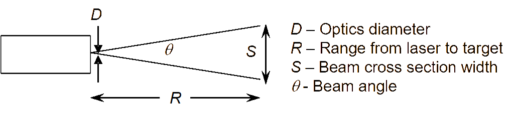
An easily manufactured and affordable collimating lens system size is between 5 mm and 100 mm diameter.
| Laser Lens Diameter | Beam Angle | Cross section diameter at 10 km |
|---|---|---|
| 5 mm | 31.5×10⁻⁵ | 3.15m |
| 20 mm | 7.9×10⁻⁵ | 0.79m |
| 50 mm | 3.1×10⁻⁵ | 0.31m |
| 100 mm | 1.6×10⁻⁵ | 0.16m |
| Ps | Source laser peak power in watts | 1 kW |
|---|---|---|
| Pr | Received signal power in watts | The minimum value is a function of receiver sensitivity and signal to noise ratio and would come to approximately 0.1 µW |
| Target Laser Cross Section (LCS) | A fighter jet has a LCS of approximately 10m2 | |
| TA | Atmospheric transmission | Haze attenuation is 0.54 dB.km-1 so loss to target is 10 km × 0.54 = 5.4 dB Converting from dB gives TA of: = 0.29 |
| Beam width angle in radians | 3.1 × 10⁻⁵ | |
| Optical efficiency of lens system | A reasonable value for either optics is 0.7 efficiency. | |
| D | Receiver aperture diameter in meters | Assuming a bi-static system (separate transmitter and receiver optics) with a larger receiving aperture of approximately 0.2m |
The Johnson Criteria [2] requires more than 16 pixels across the target for identification. Using a frequency shifted Nd:YAG laser (1.574 µm), a lens size of approximately 2 cm will focus the beam to achieve this on a 15-m target at 10 km, assuming 16 consecutive returns are obtained from across the target’s surface. Some calculations are shown in Table 2.
Range
As a minimum, the system should be able to detect targets at 10 km (2 km beyond the maximum engagement range of some SHORAD weapons) in a hazy or foggy environment. A typical Ladar range equation [5] and example parameters for this scenario are used to prove that Ladar is capable of achieving this with a 1-kW peak power laser.
(3)
Range resolution and maximum unambiguous range
It is shown that with a pulse width () of one nano-second (1 ns or 10–9s) and pulse repetition frequency (PRF) of 25 pulses per second (pps) the range resolution is 15 cm. This allows sufficient resolution to give the image some depth, which will aid in the identification process.
(4)
where c is the speed of light (3 × 10⁸ m.s–1)
Maximum unambiguous range (that is, the range beyond which consecutive echoes could be confused) extends far beyond the maximum transmission range.
(5)
Scan rate for detection
Very low level (VLL) GBAD targets often fly below the horizon. Target detection (using Radar) in a cluttered environment normally dictates a Doppler solution. The clutter in this case, may be returned echoes from objects on the ground, which is within the targets vicinity. The target is detected by virtue of the fact that its velocity (or the velocity of a moving part such as the rotor) will induce a frequency shift in the returned signal (Doppler shift). In order to detect Doppler shifts a bank of filters is required. The bank must have a total range, which can cater for the target moving at maximum speed toward and away from the detector. Individual filters in the bank must be sensitive to the small shift associated with the target moving at minimum speed toward and away from the detector.
Adopting elementary radar theory [7] and aking a minimum target velocity of 200 knots (100 m.s–1) and a maximum velocity of 500 knots (250 m.s–1) the required Doppler range can be calculated.
(6)
Hence the required bandwidth of an individual filter may be 120 MHz so it is sensitive to minimum Doppler frequency shift of 127 MHz.
(7)
Required total bandwidth of filter bank is from –317 MHz to 317 MHz (634 MHz) to account for the fact that the target may be approaching or receding. Resulting in a requirement for at least six frequency filters (bank bandwidth divided by individual filter bandwidth). This means at least six pulses must be returned from the target for so that the returned shift is detected by one of the filters in the bank.
Increasing the number of echoes required means that the system must be pointed at the target for a longer period. Such a dwell time would require a scan rate () of:
(8)
This equates to a sector of one-degree taking two minutes to scan. Obviously this is impractical for GBAD applications and a much larger beam width and higher PRF is required if a pulsed Doppler solution were to be pursued.
The point being made is that it is feasible to scan a target with a series of pulses to gain a pseudo image for identification, but it is not feasible to use the same device to detect the target. The Ladar must be cued by another device to a very high level of accuracy.
Furthermore the Ladar would need to be cued in real time while it scanned the target due to the target’s movement between consecutive pulses. This is certainly feasible with an accurate radar tracker passing updated track information at a rate greater than the PRF of the Ladar.
The primary concern then becomes distortion of the image if the target changes aspect. Recall that to create an image, it is necessary to gain a sequence of echoes that have such good range resolution; a depth profile may be developed. If the target is rotating during the scan period then a warped image will result.
Advanced LADAR research
Ladar should not be dismissed as a means of identification of GBAD targets. There is significant research in the area of using a mode locked laser and a high-speed detection system for the identification of targets. At this stage, the range to target and surface depth information may be determined over short distances and the technique in theory may be extended to ranges beyond 10 km [8]
Mode locking is where the resonant modes of the laser are combined to produce a string of very short pulses (pico-seconds, 10–12s). The very short pulse width permits surface depth resolutions below one millimetre in theory but tens of centimetres in practice. Mode locking allows for PRFs in the same magnitude as the laser’s own frequency (megahertz), both of which theoretically permit gaining enough target surface samples to build a complete profile in milliseconds.
With such a high PRF, each individual pulse cannot be distinguished from the next or previous (aliasing) hence a returned echo from the target cannot be determined. Delaying some pulses in accordance with a pattern so that the echoed train of pulses is recognisable is used for anti-aliasing. Correlating the transmitted train and returned train will result in a peak pulse, which can be used to measure the range to the target using the equation:
(9)
where t is the time for the pulse’s round trip and c is the speed of light. The target of depth L will ‘smear’ the peak pulse to a width of 2L/c. [8] As each reflecting surface along the beam within the target provides an echo, which at this stage is individually indistinguishable within the modulated peak.
For reliable identification purposes, the technique is dependent on all facets of system development. This is especially true for the higher power requirements of the 10-km range GBAD application.
Summary
The brief discussion on laser safety established that when designing a tactical military laser system for the battlefield, the wavelength must be outside of the visible and IR-A laser spectrums for a more eye-safe solution.
There are also a number of environmental factors that may significantly affect laser performance, especially if a powerful and/or a continuous-wave solution is developed. These factors and other laser performance considerations will be considered when calculating the signal-to-noise ratio (SNR) in Part 3 of this series.
In keeping with the theme of this series of papers, initial calculations have been provided for Ladar as a means of identifying targets beyond the range of SHORAD weapons. While the high frequency does provide a high resolution for a respectable component size, an additional device would be required for cueing and real-time tracking (and possibly intelligent prediction) of the target’s movement.
A more suitable solution would be to use fewer pulses to illuminate the whole target at once and then receive the echo on a detector array with enough elements to capture an image of sufficient resolution. This is the essence of the Burst Illumination Laser, which will be presented in Part 3 of this series.
References
[1] B. Kellaway and M. Richardson, “Laser Analyis—Part 1”, Journal of Battlefield Technology, Vol. 7, No. 2, November 2004.
[2] Surveillance & Target Acquisition Systems 2nd Ed, Richardson et al, Brassey’s, 1997, ISBN 1 85753 137 X.
[3] Laser Safety, Australian and New Zealand Safety Standard (AS/NZS) 2211.1, 1999.
[4] Military Laser Safety, Joint Service Publication (JSP) 390, Ministry of Defence (UK), 1998 edition.
[5] G. Cochrane, Course Notes—Laser Safety Officer Course, Australian Defence Force Academy, Canberra.
[6] Active Electro-Optical Systems, C.S. Fox (editor), Vol. 6 of The Infrared and Electro-Optical Systems Handbook, published by SPIE Press, 1993.
[7] Introduction to Radar, A lecture series presented by R. Picton, Royal Military College of Science, Shrivenham UK, September 2003.
[8] R. Peterson and K. Schepler, US Air Force Research Laboratory, Sensors Directorate, January 2003.