
Volume 7, Number 2, July 2004
Laser Analysis—Part 1
Abstract
This paper is the first in a series on laser technology. The focus is primarily the ground-based air defence (GBAD) scenario but is applicable to other ground, air and maritime environments. The purpose of the series of three papers is to investigate a viable technique which may be used for the identification of ground-based air defence targets. Part 1 introduces and describes areas of laser technology that are common-place on the modern battlefield. It also introduces some more recent developments and their applications which are discussed in greater detail in the subsequent parts. Part 2 then discusses laser safety, factors affecting laser performance and LADAR. The calculations in Part 2 demonstrate LADARs potential as a long-range (>10 km), 24-hour, all-weather imaging capability. Part 3 examines burst illumination laser (BIL), which is the chosen technique for the GBAD target-identification problem. A method of calculating BIL performance is shown and the results from the authors’ calculation tool are presented.
Introduction
The maximum range of a short-range air-defence (SHORAD) weapon system usually exceeds the range at which the operator can identify a target as hostile. For air defence operators, who are usually required to identify before engaging, the anomaly is obvious and the constraints imposed by rules of engagement (ROEs) become a source of frustration. More importantly, the capability investment in a weapon can not be fully realised if its range is effectively halved due to the operator’s maximum identification range.
As there will always be a need to identify targets when there is the possibility of friendly and civilian air space users, the answer to the anomaly is not to change the ROEs but to investigate a suitable means of identification beyond the weapon system range, preferably capitalising on the considerable investment in trustworthy visual aircraft recognition training. This has been the motivation to analyse laser technology.
Why not passive electro optics?
Passive electro optics, typically IR systems, offer a 24-hour limited all-weather capability but do not provide an easy solution for identification at ranges beyond that of SHORAD weapons (6–8 km). Passive electro optics are intrinsically dependent on the strength of the targets signature and is affected by the prevailing atmospheric conditions, neither of which usually lend towards obtaining a suitable image for identification beyond about 4–6 km.
Even if a targets signature can penetrate the atmosphere beyond this range, it is often not suitable for identification. Mid-Wave Infrared (MWIR) (3–5 μm) signatures for example, typically have the best penetration of hazy/humid conditions; but the primary MWIR signature of a fighter jet is the exhaust plume, which is good for detection but not a unique feature suitable for identification purposes. The thermal signature of the airframe peaks in the long-wave IR (8–14 μm) which is significantly affected by absorption in humid atmospheres. Signatures in the LWIR and MWIR are also becoming harder to detect in the advent of low emissivity coatings and plume suppression/dispersion techniques.
Laser technology
Due to their short wavelengths, IR bands offer higher resolution (compared to microwave) while retaining the kind of equipment size that can be deployed into the field.
Battlefield laser applications include:
- laser range finding (LRF);
- target illumination or designation for homing guidance;
- laser spot tracking for target tracking;
- tactical high energy laser (THEL) for hard kill of immediate threats;
- beam guidance of a missile;
- fusing for warhead detonation, missile guidance and target recognition;
- laser detection and ranging (LADAR); and
- burst illumination laser (BIL) for identification.
Of these applications, LADAR, THEL and BIL are the only three not currently in military service. Some advanced applications of laser fusing such as scanned beam recognition are also not yet in military service. All other applications are proven and prolific on the modern battlefield.
Laser range finding
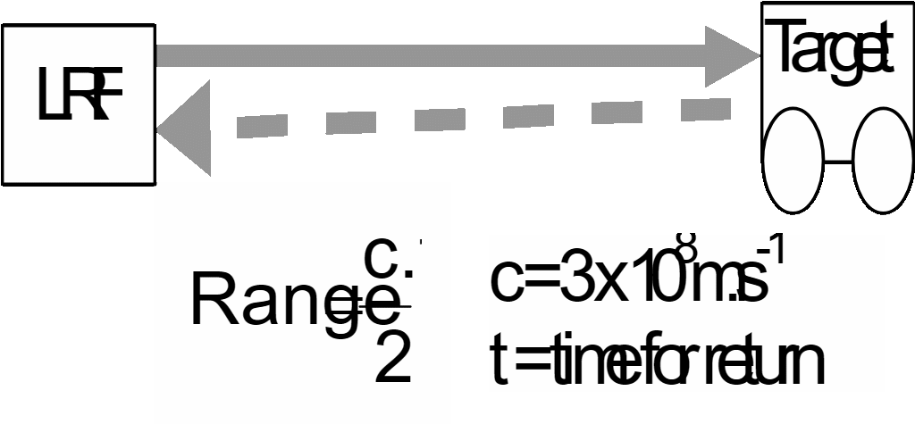
A laser range finder (LRF) is used to calculate the distance to a target by measuring the time taken for laser light to complete the round trip from the transmitter to the target and then back to the receiver.
The LRF is the most common laser application on the battlefield. There are many types and configurations available for vehicle fitting (mainly tanks and AFVs), or hand-held for artillery forward observers and infantrymen. Current research involves bringing the bulk and power usage down. The most advanced LRF in open publications is the Micro Laser Range Finder (μLRF) developed for the US Army [1].
In 1975 LRFs were larger than a shoebox, used mains or vehicle power and had ranges of about 8 km. In 1999, for the same range, the μLRF was capable of approximately 750 shots (range measurements) with a single lithium Energiser™ ‘AA’ size battery. Figure 2 depicts the μLRF and the principle of using a LRF.
![Micro LRF (after [1]).](/journals/journal-of-battlefield-technology/volume-07/issue-02/assets/7-2-6-kellaway/figures/figure02.jpg)
Worthy of note is that Figure 2 is larger than life size. The actual unit is 56 mm across, yet can still provide accurate measurements out to 8 km.
Target designation for guidance
A target designator illuminates a part of the target surface so that the laser frequency is scattered from the target. Laser designators have been used by ground forces since the early 1960s and are very common today. For example, laser-guided bomb units (LGBU), which contain a laser spot tracker, have been fitted to the NATO Mk 81 and 82 bombs since the early 1970s. The principle of operation is that a designator from the delivery aircraft or a soldier on the ground illuminates the target and the bomb can home on the scattered radiation.
The same principle is applied to the semi-active homing of missiles. The launcher, ship or aircraft can illuminate a target for the homing guidance of its own missile or another platforms missile. For example, a helicopter or fighter jet could identify an aircraft and then illuminate it while the ship fires the missile, or the helicopter may identify and engage while the ship illuminates. The ship can obviously carry more missiles and use a higher-power designator, while the helicopter has view and reach advantages. It is feasible for missiles and designators to be fitted to all platforms so that the commander has options available for various tactical situations.
Laser spot tracking
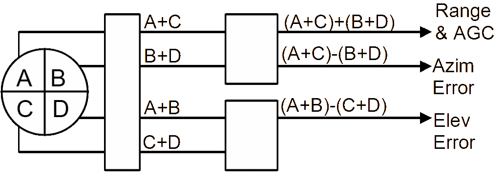
The tracking component for the above is an IR or laser receiver, referred to as a laser spot tracker (LST). These are very small, simple, rugged and inexpensive devices usually consisting of a microchip and quadrant detector, for which the material is optimised for the transmitted laser. The chip contains a program to provide up, down, left or right commands to the guidance unit by calculating the azimuth and/or elevation error from the sum channel circuitry.
| Name | LST Model 750-13 with 750-14/23 processor |
|---|---|
| Detector | Silicon - enhanced for 1.06 μm. 5.3 mm diameter quadrant cell A-R coated window. Optimised for 20-ns YAG Laser. |
| Dynamic Range | 300 nW to > 0.1W peak |
| Power Requirement | 5V at 0.2A typical or 9V at 50 mA typical |
| Size | Detector: 2.64-cm diameter, 0.66-cm height, 12 pin, 15-g mass Processor: 2.64 cm × 1.87 cm × 0.55 cm, 22 pin, 15-g mass |
| Features | Sum channel detection and good on axis direction |
A security code within the processor will be matched to the transmitted laser code so that the weapon homes on the correct laser spot and is not distracted by other laser spots, sun glint, and so on. The LST in Figure 4 made by Analogue Modules Inc. represents a typical laser spot tracker.
![Detector and processor of a LST. [2]](/journals/journal-of-battlefield-technology/volume-07/issue-02/assets/7-2-6-kellaway/figures/figure04.png)
LSTs may also be integrated with other fire control or navigation systems. As an example of this application, a LST is used in the Comanche and Apache Attack Helicopters to show the pilot information on targets that are being designated by a third party. This information is displayed on a head-up displays (HUD).
Tactical high energy laser
The tactical high energy laser (THEL) involves the use of a highly directional and powerful laser to heat the target and induce effects such as warhead detonation or fuel tank rupture/fuel combustion. In 1996 the US Army first tested a megawatt-class, deuterium-fluoride, chemical laser against a rocket in flight. The success began the THEL program which has since successfully destroyed 25 medium range rockets in flight. [3] Figure 5 depicts a THEL engagement sequence.
![THEL engagement sequence. [3]](/journals/journal-of-battlefield-technology/volume-07/issue-02/assets/7-2-6-kellaway/figures/figure05.jpg)
THEL currently relies on its own radar tracker, fine beam tracker and fire control system—all of which are large, expensive and require a lot of power. Although the system shows promise for close-in hard-kill of threat missiles, the engagement time is currently too long. Furthermore, the system currently relies on a predicted ballistic trajectory data to calculate firing solutions and engaging agile missiles is still under research. Hence, the use of laser for hard kill of immediate GBAD threats such as incoming missiles or aircraft is still a concept.
Beam guidance of the missile
Laser ‘beam riding’ is a guidance method in many GBAD and anti-tank guided weapons (ATGWs). The laser beam acts as a long cone for the missile to travel in until it reaches the target. The missile is commanded by sending signals down the beam or providing a distinctive pattern so that the missile can calculate how far it is from the centre of the beam and make adjustments. For an automated or semi-automated command to line-of-sight (ACLOS or SACLOS) system the beam is fixed on the target by an operator or target tracker. The beam may be focused by a zoom program and lenses on a worm drive so that the cone forms a ‘basket’ during the initial gathering phase and is then narrowed for best accuracy and maximum intensity during mid and terminal guidance phases.
This mature and reliable technology is readily available and comparatively cheap. The transmitting site can be as simple as a combination of laser emitting diodes focused into one beam and then a selected pattern is generated by a series of rotating prisms. Laser beam guidance is highly resistant to electronic counter measures (ECMs) as the laser receivers are not in the line of sight to the target and the only obvious way of disrupting the signal is to disturb the line of sight between the transmitter and the missile.
The effectiveness of the laser beam to provide continuous command to the missile out to maximum range depends on the factors discussed in Part 2 of this series of papers. They are primarily: transmission power, optics, atmospheric propagation and maintaining line-of-sight to the target.
Laser fusing for warhead initiation
Active IR (laser) fuses are common in missiles. When it is not required or feasible to hit the target, they offer the guidance system the flexibility to deliver the missile within a certain range or ‘miss distance’ to the target. Hence, they are often referred to as proximity fuses. Although inexpensive laser fuses are effective out to ranges of 10–20m, the required proximity is a function of the warheads lethal radius and the predicted performance of the guidance system. Figure 6 illustrates warhead initiation and the Rapier fuse.
![Warhead initiation and the Rapier fuse. [4]](/journals/journal-of-battlefield-technology/volume-07/issue-02/assets/7-2-6-kellaway/figures/figure06.gif)
The principle of a laser proximity fuse is to transmit a number of laser beams or a single laser fan into open space in a given direction and sector around the missile. When the transmitted laser strikes the target surface, the reflection is detected and a signal may be sent to initiate the warhead. Inherent features of laser fusing are:
- measurement of range and range rate if required,
- rejection of targets and clutter beyond lethal range by range gating, and
- low cost optics, transmitters and silicon pin detectors.
Fuse integrated guidance
The laser proximity fuses used for GBAD missiles are usually not suitable for surface to surface or air to surface applications, due to the presence of other reflecting objects on the land. More advanced fuses, such as the FITOW Over Top Attack Proximity Fuse incorporate terrain and target profiling algorithms so that the missile does not collide with the ground and only initiates the warhead when the laser reflections match a step profile of the target.
Using a stored target profile within the fuse processor can not be relied upon for target recognition/identification because the step profile could match another object of similar shape or a friendly vehicle of the same shape. Hence the missile must only be guided to a target that has already been identified by other means. The capability to use laser fuses for identification is currently emerging in scanned beam sensor techniques.
Scanned beam sensor fuses
Current research has proven that a laser beam scan from a missile passing the target is capable of generating a two-dimensional (2D) or three-dimensional (3D) profile of the target, of sufficient resolution to allow for identification. The technique relies on the following technically challenging areas:
- The profile (image) can only be generated for the section of the target that the missile passes. Although a section of the target may allow for identification and the fuse may have a look-ahead angle, it is reasonable to assume that the missile must pass the target at least once to gain a suitable image.
- The resolution is dependent on range, sample rate or pulse repetition frequency (PRF) and the sum of the missile plus target velocities.
- The target and missiles motions and trajectories must be accounted for. Any variation from a parallel scan will distort the image. Correcting the trajectory distortions is mathematically intensive. Accounting for missile roll adds to the complexity of the missile as multiple sensors and roll stabilisation or measurement is required.
- If the image is sent to an operator then the missile will require a means of communication to transmit the image and receive a subsequent command. Furthermore, while the communication is taking place, the missile must remain in flight and be capable of returning to the target. This scenario demands complex guidance, additional sensors and greater range.
- If automated target recognition/identification were used then an advanced image processor would replace the communication system. Such technology is not yet mature enough to be reliable or trustworthy and processing time would also demand a second pass for engagement.
Thales Missile Electronics Ltd, have developed an experimental scanning pencil beam transceiver and a microchip laser that have produced 3D imagery suitable for recognition/identification purposes and small enough for inclusion in a missile.
Figure 7 demonstrates the promise of scanned beam technology for future systems. But even without mentioning the high complexity and cost, it is assessed that the scan beam technique and hardware would not be ready to aide recognition tasks until beyond 2020.
![Simulated scanned beam image. [4]](/journals/journal-of-battlefield-technology/volume-07/issue-02/assets/7-2-6-kellaway/figures/figure07.gif)
Detection and ranging using LADAR
When operating in the ultraviolet to infrared region of the electro-magnetic spectrum, any wavelength-dependent considerations of radar design are reduced in orders of magnitude when compared to conventional microwave radar. This offers notable advantages in antenna size and resolution, but traded against reduction in range due to poorer atmospheric transmission. LADAR has such high resolution that it could conceivably be used for crude imaging suitable for GBAD target identification. For this reason, performance parameters and initial calculations have been completed and are demonstrated in Part 2 of this series. The calculations will assess LADAR under the following performance criteria: atmospheric transmission, angular resolution, range resolution, maximum unambiguous range, minimum range and scan rate.
Burst illumination laser
The emerging technology of Burst Illumination Laser (BIL) is an active system, which illuminates the target and views the reflected radiated from the target. The receiving camera is gated to the target’s range vicinity to eliminate unwanted noise and a gated receiver bandwidth encompassing the transmitted laser frequency is used to eliminate other light sources. The concept has recently been demonstrated in a favourable environment against maritime targets. [5]
BIL technology is available and offers a number of advantages that make it a viable option for target identification. [6] They are:
- high spatial resolution,
- immune to sun glint and scatter from haze or aerosols,
- short illumination requirement for reduced blurring,
- video like imagery,
- small system size, and
- eye safe.
At this stage, BIL must also be cued by another surveillance device. However when compared to LADAR, the technique offers nearly instant ‘snap shot’ imagery without a scan period and extensive processing. BIL performance calculations and a BIL calculation tool introduced in Part 3 of this series.
Summary of part 1
This paper has reviewed common place usage of laser technology on the modern battlefield. It has also looked at a few less common laser techniques and two of these namely LADAR and BIL will be discussed in greater detail in Parts 2 and 3 with the eventual aim of outlining a solution to the GBAD identification scenario.
References
[1] J. Nettleton, D. Barr, B. Schilling and J. Lei, Micro Laser Range Finding Development; using a Monolithic Approach, Night Vision and Electronic Sensors Division (CECOM RDEC NVESD), Fort Belvoir, VA, 1999.
[2] Analogue Modules Inc., “Laser Spot Tracker Hybrid Set” URL: www.analogmodules.com, last accessed Nov 2003, Longwood, Florida 32750-3426. USA
[3] “Tactical High Energy Laser (THEL) Program” URL: www.defense-update.com, last accessed: Nov 2003
[4] G. Buzard, Fusing Technology, Thales, UK, Mar 2003.
[5] D. Manson, Analysis of Maritime Burst Illumination Laser Trial and Recommendations for Future Research, QinetiQ UK, Feb 2003, Restricted QinetiQ in Confidence.
[6] S. Anderson, “Active Night Vision System Captures Near-IR Images”, Laser Focus World, Vol. 32, No. 5, May 1996.