
Volume 7, Number 2, July 2004
Scale-Model Testing of Soil-Vehicle Systems
Abstract
Full-scale testing of vehicles is notoriously difficult and expensive. Invariably only a small range of vehicle configurations and soil conditions can be explored and it is difficult to ensure consistency and uniformity of terrain. Scale-model testing may provide a more versatile and cost-effective method for exploring the behaviour of off-road vehicles. This paper describes some of the simple rules which have to be observed when modelling vehicle operations on soil and presents results from three case studies of scale-model tests on tracked vehicles and earth anchors carried out in soil bins at The Royal Military College of Science (RMCS) in the United Kingdom. The results are shown to correlate well with theoretical predictions of full-scale performance and with empirical predictions based on full-scale trials.
Introduction
One of the major inhibitors of progress in the field of terramechanics has been the complexity and cost of conducting full-scale trials. Such trials are invariably specific to a particular vehicle configuration and terrain type and are often subject to variability in the ground conditions, local topography and weather. Moreover it is very difficult to vary the physical properties of the running gear in order to explore the impact of, say, track breadth or suspension stiffness on mobilisable draw-bar-pull (DBP).
This paper describes a number of investigations into soil-vehicle interaction conducted by the author in the Mobility Laboratory at The Royal Military College of Science, Shrivenham (RMCS), UK. The paper argues that such model tests offer a number of advantages. These include very effective control of the soil conditions and the ease with which geometry and loads can be changed at minimal cost. Hopefully it will not rain in the laboratory, nor will the local farmer come along and plough up the test track part way through the trials programme. On the other hand, a scale-model test is just a scale-model test. At some stage in the work, it will need some degree of validation at full scale.
Theory
The scaling of soil-vehicle interaction was examined in some detail by Schuring [1]. This provides a viable basis for investigations at model scale. Such investigations could yield, for example, information on the resistive force which could be mobilised by an anchor, the draught force on a plough or the draw-bar-pull which could be generated by a main battle tank. In fact force estimation is often the focus of such studies. A useful dimensionless parameter (or π group) which is often adopted in scaling work is therefore:
(1)
in which:
F is a characteristic force (such as draw-bar-pull);
γ is the bulk unit weight of the soil (that is, density × g); and
l is a characteristic length (such as blade height or track width).
Dimensional analysis is based on the concept that this π group is a function of a set of other dimensionless groups. The key to successful scaling of any physical system is the correct identification of the salient parameters which govern the physical process. These, too, are combined into dimensionless π groups. Our force π group (Equation (1)) is now a function of the other assembled π groups:
(2)
The scaling law can now be stated as follows:
If the value of each of the π groups on the right hand side of Equation (2) takes the same value at full and model scale, the value of the force π group on the left hand side of Equation (2) will also take the same value at full and model scale.
The scaling process is therefore quite straightforward provided no conflicts arise from the requirement to keep all of the π group values the same at model and full scale. In the case of soil-vehicle interaction, a conflict can arise if the forces generated are affected by the speed of the process. However, some processes are very slow (such as anchoring) or are relatively insensitive to speed. By excluding speed from the analysis and with some careful manipulation of soil properties, effective and successful scale modelling can usually be achieved.
Case study 1—earth anchors
During the 1980s, the author carried out design calculations for earth anchors for both Challenger Armoured Repair and Recovery Vehicle and for the Recovery variant of Warrior. In each case, it was deemed desirable to carry out tests at model scale to confirm that the anchors would meet the stated requirement.
In each case the requirement was stated in terms of the resistive force which could be generated by the blades when fully dug in to soils with certain specified shear strength properties. These included a saturated clay, a dry sand and a ‘typical top soil’.
On the assumption that the anchoring process was, essentially, quasi-static, the following π groups were identified:
(3)
where:
F is the anchor force (kN);
γ is the bulk unit weight of the soil (kNm-3);
φ is the angle of friction of the sand (degrees);
c is the soil cohesion (kNm-2);
δ is the friction for soil/metal contact (degrees);
a is the soil/metal adhesion (kNm-2);
β is the blade shape ratio;
q is the soil surcharge (kNm-2); and
l is a characteristic length (m).
Provided each of the groups on the right-hand side of Equation (3) has the same value at full and model scale, the quantity in Equation (1) will also have the same value at full and model scale. Assuming γ to be the same for full- and model-scale soils, for a one-eighth scale model, the ratio of the force at full scale to that at model scale will be 512 (that is 83).
In addition:
- The model must have the same geometrical shape as the full scale design.
- The surcharge q must be reduced by a factor of 8.
- φ and δ must be the same for the model and full-scale soils.
- c and a must be reduced by a factor of 8.
During the course of the experiments a number of readings were taken at model scale, which had to be factored to give the corresponding value at full-scale. All angular rotations were factored by 1, all translations by 8, all stresses by 64 and all forces by 512.
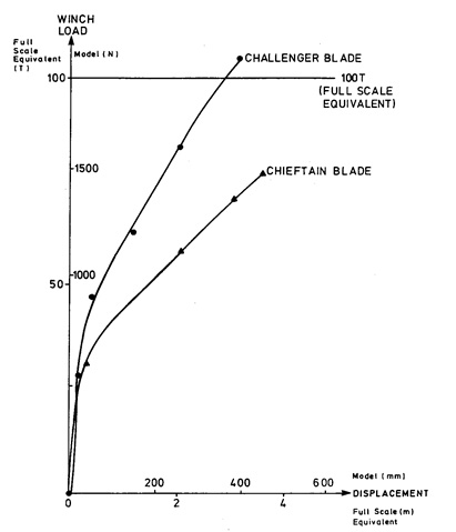
The series of tests yielded useful information on the magnitude of winch pull which can be resisted by the soil, and this is compared, for in-line pulls, with the blade previously fitted to Chieftain in Figure 2.
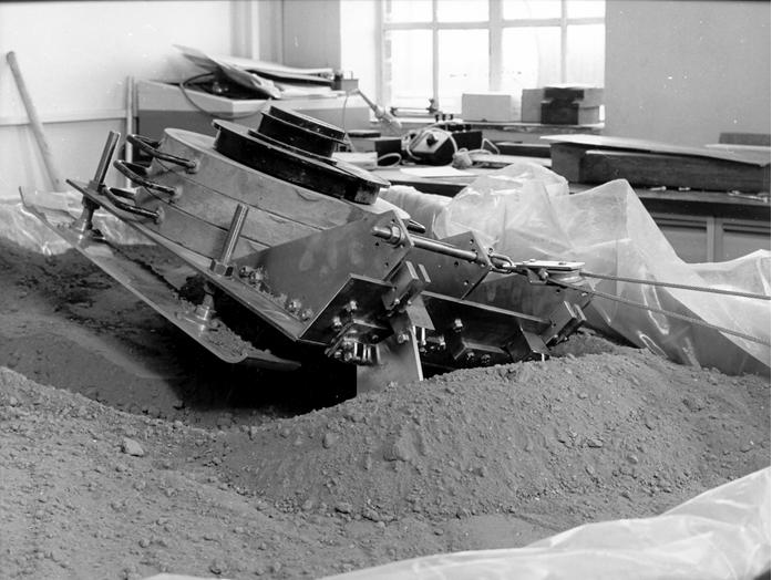
In addition to straight line pulls, it was possible to investigate winching operations on inclines and skew pulls (Figure 3). Moreover it was possible to measure the forces in the blade-support mechanism and these correlated well with theoretical predictions.
A similar set of tests were carried out on the vehicle with the blade in the dozing configuration to determine the required draw-bar-pull for dozing and the linkage forces.
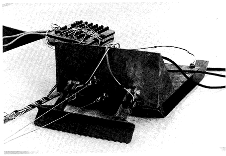
In a separate set of trials, the performance of a rear-mounted anchor blade for Warrior was investigated. A number of different blade and mounting geometries were trialled resulting in the configuration shown in Figure 4. One of the concerns at the time was the magnitude of the reaction force between the blade and the hull. Load cells were mounted in the hull to measure these, which yielded data on which recommendations could be based for hull reinforcement.
Case study 2—up-armouring challenger for desert operations
With the increased interest in desert operations, a project was undertaken to assess the impact on mobility of up-armouring Challenger MBT. A one-tenth scale, single-track model of Challenger was constructed (Figure 5) and tested in the sand mobility bin at RMCS. The speed of the tracked model and the carriage in which it is mounted can be controlled independently and so the slip between the vehicle and the ground can be varied. A series of tests was run to represent a range of vehicle weights. During each test the slip was varied and both the peak draw-bar-pull and the draw-bar-pull at 20% slip were recorded. A typical DBP-versus-slip graph is shown in Figure 6, and the dependence of DBP on weight is shown in Figure 7.
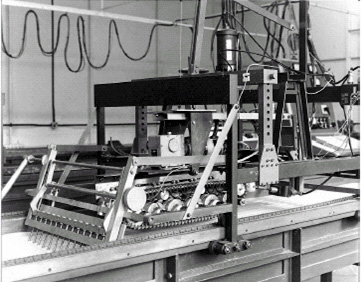
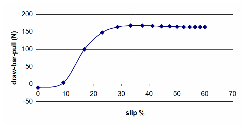
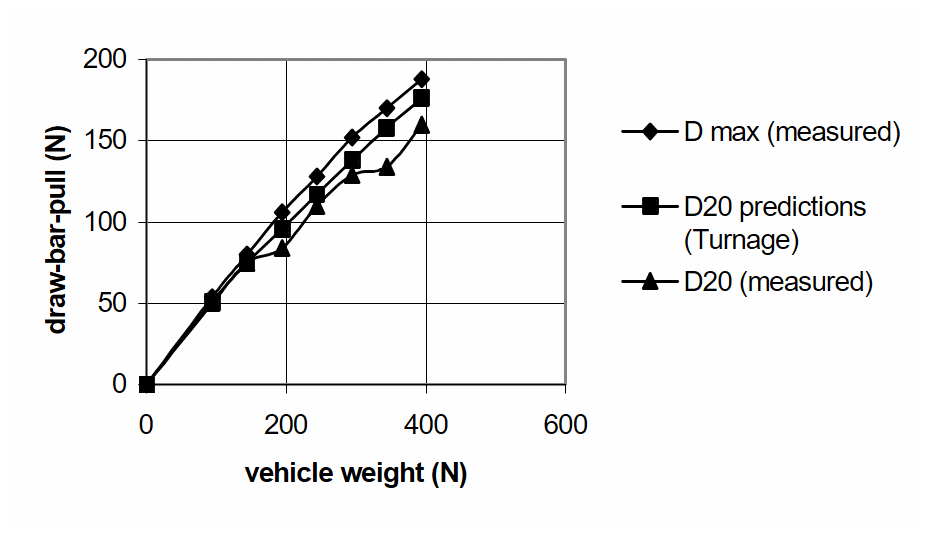
The experimental results are compared with predictions based on work by Turnage [2]. A good correlation between the scale-model results and the predictions of Turnage which are, essentially, an empirical fit to a set of full-scale results, confirms the validity of the scaled experiments.
Case study 3—all-wheel electric-drive tracked vehicles
Having established the validity and usefulness of scale-model testing, it is possible to investigate, at model scale, concepts which, for one reason or another, are not yet realisable at full-scale. One such project was the investigation of an all-wheel-electric-drive tracked vehicle in which power is fed to electric motors housed in the roadwheel hubs. A number of potential advantages could accrue from such a system including:
- reduction of volume and mass of vehicle propulsion system,
- greater flexibility in design of vehicle layout,
- elimination of gear-changing and clutch systems,
- reduction in track tension leading to the use of band track,
- improved obstacle crossing,
- intelligent power delivery to where it is needed,
- better residual mobility after mine damage, and
- stealthy movement and regenerative braking/steering.
In order to test out some of these claims, two scale models were built:
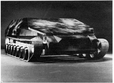
- a one-tenth scale, single-tracked, all-wheel-drive model (Figure 8); and
- a one-fifth scale, double-tracked, free-ranging, all-wheel-drive model (Figure 9).
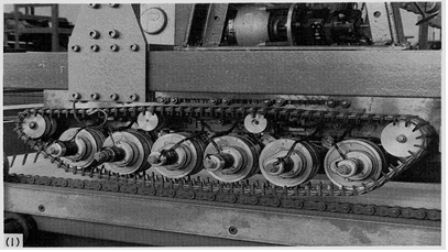
By using an instrumented link, (Figure 10), track-tension measurements were made for the single-track model (Figure 11). Figure 11 shows the reduction in track tension which the concept had promised.
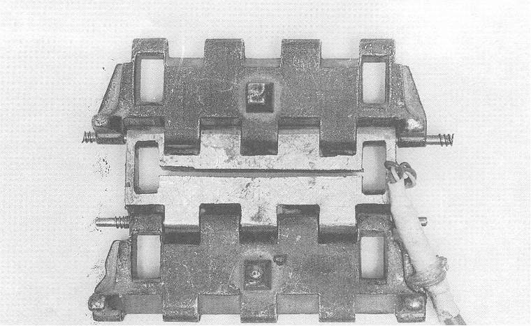
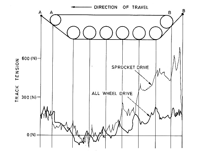
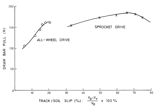
Figure 12 shows the draw-bar-pull versus slip characteristics for the all-wheel-drive and sprocket driven systems, suggesting that less energy will be wasted in the new system.
Technology has now moved on and such a system is now achievable at full-scale. The point made here is that it was possible to investigate the concept at model scale before it was economically achievable at full scale.
Conclusions
From this work, the following conclusions can be drawn:
- The rules for scaling soil-vehicle interaction are well established.
- Results from tests at model scale have been correlated with equivalent values from theoretical predictions and full-scale trials.
- Scale-model tests can provide a cost-effective method of investigating full-scale systems.
- Scale-model tests can be used to test out a range of candidate designs for optimum performance and to explore concepts which may be currently unrealisable at full scale.
References
[1] D. Schuring, Scale Models in Engineering, Pergamon Press, 1977.
[2] G. Turnage, Performance of Soils Under Track Loads, Technical Report No M-71-5, US Army Waterways Experiment Station, Vicksburg, MS, USA, 1971.