
Volume 7, Number 1, March 2004
Ballistic Damage in Carbon/Epoxy Composite Panels
- 1 Both authors are with Air Vehicles Division, Defence Science and Technology Organisation, 506 Lorimer St. Fishermans Bend, Victoria, 3027, Australia.
Abstract
Ballistic tests were carried out using carbon/epoxy composite panels and standard ball munitions. Impact and residual velocities of the projectiles and damage area, including delamination, of the test panels were measured. FATEPEN prediction and Dyna3D simulation were conducted. Residual velocities and hole areas predicted by FATEPEN are comparable to, but do not accurately agree with, the measured residual velocities and the visible damage areas on the specimens. Residual velocities predicted by Dyna3D are closer to the measured velocities. Similar to the FATEPEN prediction, hole areas predicted by Dyna3D are comparable to the visible damage areas on the specimens. Delamination areas predicted by Dyna3D appear to agree with the measurement reasonably well. Hence Dyna3D appears to be a useful tool for evaluation of delamination and thus structure residual strength of composite panels after ballistic impact.
Nomenclature
| Ad | Damage area |
|---|---|
| Ade | Damage area with both visible damage and delamination |
| Adv | Visible damage area |
| C | Calibre of projectile |
| E | Kinetic energy transferred from projectile to test panel during projectile penetration |
| T | Thickness of test panel |
| md | Mass of debris |
| mp | Mass of projectile |
| vi | Impact velocity of projectile |
| vr | Residual velocity of projectile after peroration |
| v50 | Ballistic limit velocity |
| v50est | Ballistic limit velocity estimated using Equations (1) and (2) |
| α | Oblique angle |
Introduction
Owing to their superior structural performance (such as high strength, high stiffness, long fatigue life and low density) polymer composite materials are increasingly used on aircraft. Some recently developed military helicopters (such as the Eurocopter Tiger) have nearly all composite airframe structures. A large percentage of the composite materials used on aircraft are carbon-fibre polymer materials.
Due to the nature of their mission, military helicopters are vulnerable to ballistic impact damage from small arms on the battlefield. The performance of carbon-fibre polymer materials, in terms of their ability to protect the occupants and internal systems of the aircraft (or armour effectiveness), and their structural integrity after ballistic impact is an important concern for defence research.
Ballistic experiments and numeric simulations were recently carried out at the Australian Defence Science and Technology Organisation (DSTO) to investigate the armour effectiveness and ballistic damage size in carbon/epoxy composite panels. The preliminary results of this investigation are summarised in this paper.
Procedures
Experiment
The carbon/epoxy material used in this work was 5-shaft, satin weave, fabric prepreg (the relevant properties are listed in Table 1). The test panels were made with four different nominal thicknesses, namely 1.28 mm (4 plies), 2.57 mm (8 plies), 3.83 mm (12 plies) and 6.42 mm (20 plies), all with quasi-isotropic lay-ups. The areas of these panels were 100 mm × 100 mm for perpendicular impact or 30° oblique impact and 100 mm × 150 mm for 60° oblique impact.
In the tests 5.56 mm (SS109), 7.62 mm (F4) and 12.7 mm (F1) ball munitions were shot from rifle guns to the centre of the composite panels that were clamped in fixed rigid frames. The variation of the projectile velocities was achieved by using different amount of propellant in the cartridges.
The impact and residual velocities of the projectile were measured using two chronographs installed in front of and behind the target, respectively. After ballistic tests, the penetration hole sizes (visible damage) on the test panels were measured. The delamination areas around the holes were assessed using both tap test and ultrasonic C-Scan methods.
Simulation
Three approaches are commonly utilised in the simulation of ballistic penetration of armour, namely, empirical methods, simplified analytical models and finite element numerical modelling. Numerous research reports with these approaches have been published [1-3]. However, most of them involve metal armour materials, some involving other materials such as ceramic or Kevlar/fibreglass composites, but few involving carbon/epoxy composites. Two simulation tools available to the authors were used in this study; namely the FATEPEN (Fast Air Encounter Penetration) package [4] that is a set of fast-running algorithms based on a combination of simplified analytical and empirical models, and the Dyna3D explicit finite-element software [5]. Both of them contain models for carbon/epoxy composite materials.
FATEPEN simulation
In the FATEPEN simulation, the projectiles were approximated as tapered steel cylinders as shown in Figure 1. The hardness 250Bhn and 70Bhn were assigned to the projectiles and composite targets respectively. The input data also include panel size and thickness, oblique angle, and projectile impact speed. The relevant outputs are projectile residual velocities, ballistic limit velocities of the panels and penetration hole sizes.
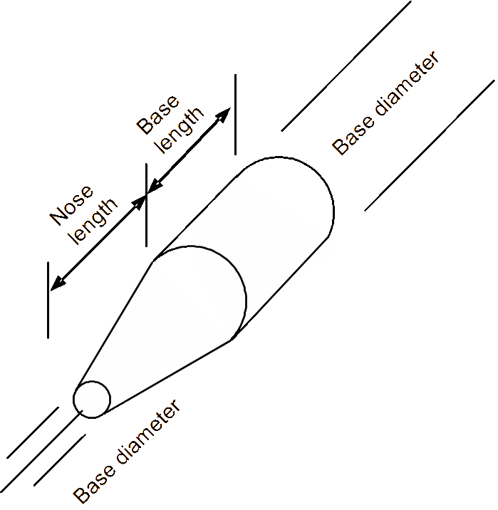
| Calliper (mm) | 5.56 | 7.62 | 12.7 |
|---|---|---|---|
| Base length (mm) | 12.0 | 15.0 | 30.5 |
| Nose length (mm) | 11.0 | 13.0 | 28.0 |
| Base diameter (mm) | 5.65 | 7.80 | 12.7 |
| Nose diameter (mm) | 0.70 | 1.70 | 3.05 |
| Weight (g) | 5.65 | 9.33 | 42.2 |
Dyna3D simulation
Simulation of ballistic impact is one of the most challenging problems for finite-element applications, involving complicated high-speed contact and material erosion failure, as well as strain-rate dependent material constitutive behaviour. For laminated composite materials, the failure mechanisms are further complicated, involving fibre breakage, matrix cracking, ply cracking, delamination, and fibre pull out (fibre debonding) [6].
With currently available options, Dyna3D may be used to tackle the contact and material erosion failure in three possible ways, namely, using Eulerian meshes with the multiple-material option, using Lagrangian meshes with the speed and acceleration coupling option, and using Lagrangian meshes with the erosion contact option [5]. With the multiple-material option Dyna3D currently only allows three multiple materials, whilst in this study, a minimum of four multiple materials would be needed, that is at least two materials for laminae with different orientations, projectile material and air (allowing the composite material to deform out of plane). Thus the multiple-material option was not utilised.
With the erosion contact option, Dyna3D firstly detects whether the contact between the projectile and composite panel has occurred. Once contact occurs, Dyna3D then calculates the element contact force and deformation using the material stiffness and dynamic impact condition. Once an element’s stress or strain reaches a pre-specified failure value, the element will be deleted. The erosion contact algorithm manages this calculation throughout the process that the projectile penetrates the target panel. The speed and acceleration coupling option works slightly differently in that the continuity of speed and acceleration of the projectile and panel elements in contact is used in the calculation. The elimination of failed elements may also be handled by using a material failure criterion. This is necessary for simulation of penetration. Both of these two options were applied in this study. The former simulates the deformation pattern better whilst the latter is preferred for prediction of residual speed of the projectile.
In Dyna3D a few composite material models are available. These materials are elastic models with different failure options. Dyna3D material type 59 (MAT-COMPOSITE-FAILURE-SOLID-MODEL) was used. This material model incorporates the maximum stress failure criterion for the three normal stresses and three shear stresses. Once the stress in the longitudinal (fibre) direction reaches the failure value, Dyna3D will delete the element. On the other hand when the normal stress in transverse or through-thickness direction, or the shear stress, reaches the failure value, Dyna3D will reduce the element stiffness in the relevant direction to a negligible value but retain the element. To remove those elements with excessive distortion in the latter case, a strain failure criterion (erosion strain of 80%) was used through Dyna3D’s “MAT-EROSION” keyword command option. The material properties listed in Table 1 were used in the calculation. Strain-rate effects were not considered due to lack of a relevant material model. (Measurement of composite material properties at high strain rates is being carried out at DSTO. The outcome may be incorporated in the computational model in the future.) The projectile was modelled initially using both elastic-perfect plastic material and rigid material properties. With the elastic-perfect plastic material, the deformation was found to be very small and the computational time very long, and thus rigid material properties were used for most of the calculations to speed computational time.
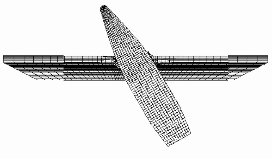
The finite-element mesh was made using eight-node brick elements (one element for each ply through the thickness). This was necessary to accurately model delamination damage. A typical mesh of the model is shown in Figure 2. For vertical impact a quarter-geometry model and for the oblique impact a half model was built. Symmetry conditions were applied to the relevant boundaries of the models and the panel was fixed along its perimeter. The load was in the form of the projectile’s initial velocity taken from the measured impact velocity.
Results and discussion
Experiment
Residual speed of projectiles, penetration hole sizes and delamination areas were measured. Selected results are listed in Table 2.
The damage pattern of the panels is illustrated in Figure 3. The hole made by the projectile has a cone shape, with the exit side larger than the entrance side. The delamination area is much larger than the visible damage area.
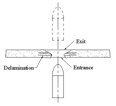
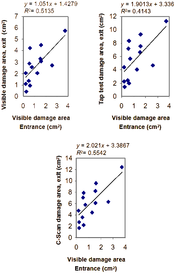
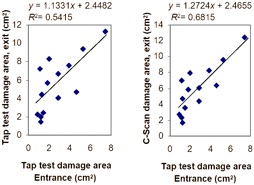
Figure 4 plots the relationship between the visible damage area at the entrance face and (a) the visible damage area at the exit face, (b) the exit damage area (including the hole) measured using tap test, and (c) the exit damage area measured using C-Scan. Since it would be difficult to measure the damage from the exit face in-situ on an aircraft in the field, the information in Figure 4 would be useful for estimating the total damage after only measurement at the entrance face. Similarly Figure 5 provides the relationship between the measured damage area from the tap test at the entrance face and that from tap test or C-Scan at the exit face.
The difference between the impact and residual velocities can give a measure of the armour effectiveness of the panel. This is calculated by first calculating the kinetic energy transferred from the projectile to the panel due to the impact resistance using the following formula:
(1)
In terms of the energy required during penetration, the ballistic limit velocity of the composite panels, v50, may be approximately estimated using the following equation [7]:
(2)
The calculated v50est values are listed in Table 3. As expected the speed decrease (difference between the impact and residual speeds) and v50est values are proportional to the panel thickness.
The 12.7-mm calibre round has the lowest v50est of the rounds tested. This implies that, under the assumption that the impact velocity is the same, the composite panels provide least protection or armour effectiveness against this round. For the 1.28-mm thick panel, the 7.62-mm calibre has the highest v50est value, whilst for the 6.42-mm thick panel, the 5.56-mm calibre has the highest v50est value making it difficult to draw a relationship between projectile size and armour effectiveness of the panels for the other rounds tested.
FATEPEN simulation
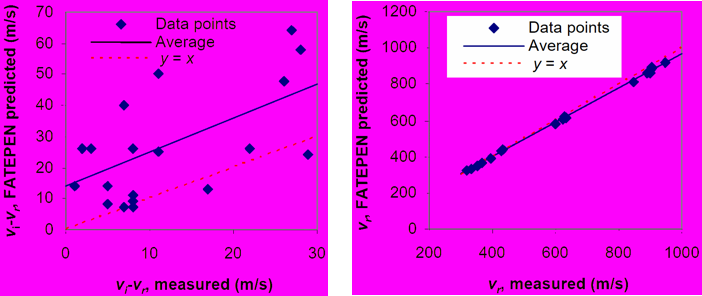
FATEPEN simulation results are listed in Table 3. Figure 6 plots the comparison of predicted and measured residual velocities. Since the residual velocity is close to the impact velocity, the comparison is made in two different ways. As shown in Figure 6(a) the agreement between prediction and measurement appears good when comparing residual velocities. On the other hand, Figure 6(b) shows significant difference between prediction and measurement in terms of the velocity reduction (vi–vr). The predicted velocity reduction is higher than the measured. (Note that in Figure 6 the line y=x indicates the location of data points for a perfectly accurate prediction.)
As shown in Table 3 the FATEPEN predicted v50 values are significantly lower than those estimated using test data with Equations (1) and (2). Due to the possible strong strain rate effects associated with the composite materials, the v50est estimated using test data may be significantly different from those obtained from the standard ballistic limit tests with lower impact velocities. Thus to acquire accurate ballistic limit velocities and make a rigorous comparison with FATEPAN prediction further tests are needed.
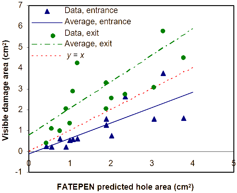
As shown in Figure 7, the hole sizes predicted are larger than the visible damage areas at the entrance side but smaller than those at the exit side. This implies that the prediction of visible damage using FATEPAN may be inaccurate.
| C (mm) | T (mm) | α | Measured | FATEPEN Prediction | ||||||
| v i (m/s) | v r (m/s) | v 50est (m/s) | A dv (cm² ) | v r (m/s) | v 50 (m/s) | A dv (cm² ) | ||||
| Entrance | Exit | |||||||||
| 5.56 | 1.28 | 0 | 357 | 350 | 70.3 | 0.25 | 0.40 | 350 | 32.9 | 0.42 |
| 2.57 | 0 | 338 | 321 | 105.8 | 0.22 | 1.08 | 325 | 54.0 | 0.55 | |
| 3.83 | 0 | 461 | 432 | 160.9 | 0.20 | 2.05 | 437 | 77.8 | 0.90 | |
| 6.42 | 0 | 977 | 949 | 232.2 | 0.74 | 2.54 | 919 | 96.7 | 2.01 | |
| 1.28 | 30 ° | 340 | 332 | 73.3 | -* | - | 333 | 35.3 | 0.48 | |
| 7.62 | 1.28 | 0 | 415 | 407 | 81.1 | - | - | 406 | 32.7 | 0.68 |
| 1.28 | 0 | 633 | 628 | 79.4 | 0.61 | 0.96 | 619 | 32.7 | 0.75 | |
| 2.57 | 0 | 633 | 622 | 117.5 | 0.52 | 1.35 | 608 | 54.8 | 1.00 | |
| 3.83 | 0 | 391 | 369 | 129.3 | 0.57 | 2.89 | 365 | 80.4 | 1.08 | |
| 6.42 | 0 | 627 | 601 | 178.7 | 0.60 | 4.23 | 579 | 101. | 1.19 | |
| 1.28 | 30 ° | 399 | 394 | 63.0 | - | - | 391 | 35.8 | 0.78 | |
| 2.57 | 30 ° | 639 | 631 | 100.8 | - | - | 613 | 58.8 | 1.15 | |
| 3.83 | 60 ° | 875 | 848 | 215.7 | 3.74 | 5.74 | 811 | 164 | 3.28 | |
| 12.7 | 1.27 | 0 | 906 | 905 | 42.6 | 1.28 | 2.03 | 892 | 21.9 | 1.89 |
| 2.57 | 0 | 438 | 430 | 83.3 | 1.56 | 3.29 | 427 | 38.1 | 1.89 | |
| 2.57 | 0 | 908 | 905 | 73.7 | 2.60 | 2.74 | 882 | 38.1 | 2.35 | |
| 3.83 | 0 | 899 | 892 | 112.0 | 1.57 | 3.07 | 859 | 57.5 | 3.05 | |
| 6.42 | 0 | 909 | 898 | 141.0 | 1.59 | 4.49 | 859 | 73.5 | 3.77 | |
| 2.57 | 30 ° | 901 | 899 | 60.0 | - | - | 875 | 40.8 | 2.72 | |
Dyna3D simulation
The 12.7-mm calibre case was selected for the Dyna3D simulation. Figure 8 shows the deformation of the panel caused by the projectile during the penetration. Four microseconds (4 µs) after contact (Figure 8(a)), the projectile tip has entered the panel by compression/erosion. The material above the tip is pushed up and the material on the lower part of the contact face is squeezed laterally. At 14 µs (Figure 8(b)) the projectile has clearly penetrated and the panel deformation consists mainly of upward bending and lateral squeezing. As described the Simulation (Dyna3D Simulation) section, when the matrix failure strength is reached, the relevant stiffness values are reduced so that they are negligible and the element deformation in the relevant directions will be larger accordingly in the subsequent time steps. Figure 8(c) shows that when the full-hole size is reached delaminations spread to a large area. These delaminations could be due to high through-thickness stresses or in-plane/interlaminate shear stresses. The FEM calculation indicates that the spreading of delamination is due to in-plane/interlaminate shear stresses exceeding the material shear strength. Figure 8(c) also shows the downwards displacement of the lower part of the panel adjacent to the projectile due to the squeezing effect, which appears more pronounced compared with what was observed on the tested specimens. Except for this last observation the deformation pattern predicted corresponds reasonably well to the test results. Note that, as described in the Simulation (Dyna3D Simulation) section, the erosion criterion (element deletion criterion) is different from the failure criterion, hence the area with element failure is larger than the area where the elements are removed.
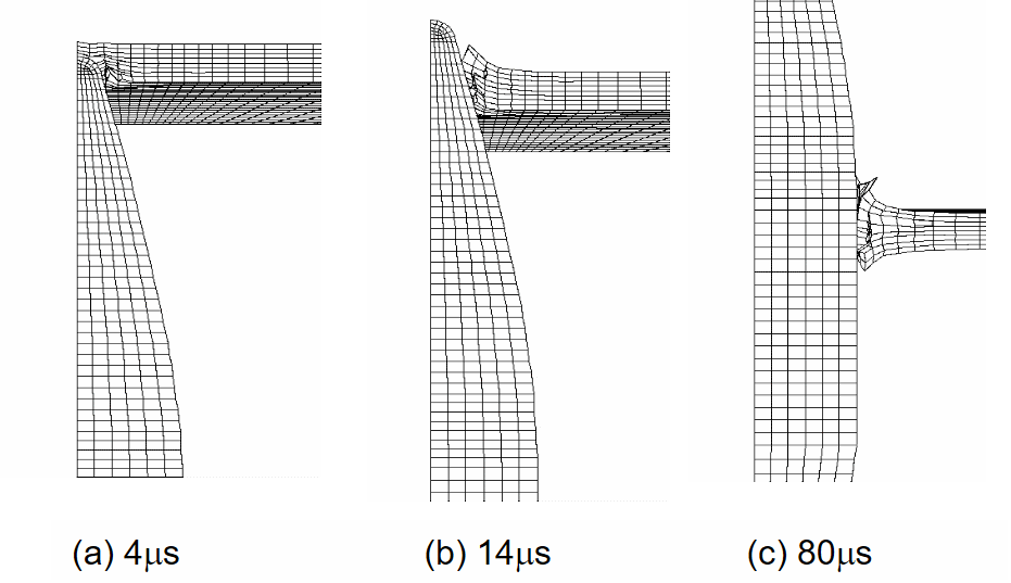
Figure 2 shows the Dyna3D simulation of oblique (30°) penetration. The right side deformation is similar to that in the perpendicular penetration case described above and the material on the left side is pressed downwards corresponding to what was observed on the test specimen.
The predicted residual velocity, maximum visible damage area and delamination area are listed in Table 4. Compared with FATEPEN prediction shown in Table 3, the residual velocities predicted by Dyna3D appear closer to the measurement values.
The predicted visible damage size is influenced by the deformation pattern and erosion criterion. Since the erosion (element deletion) criterion is somewhat arbitrarily set, it is not expected that the predicted visible damage size would agree accurately with the test results.
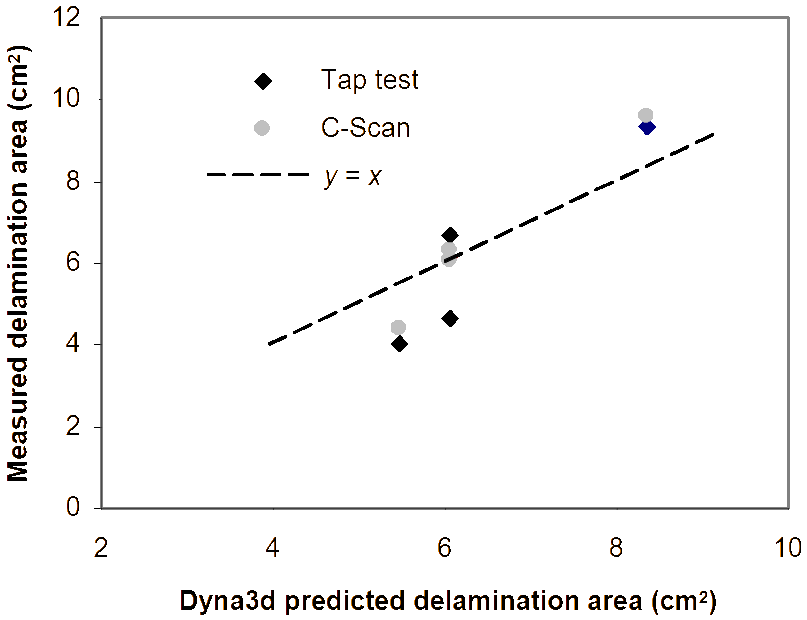
Figure 9 compares the predicted and measured delamination areas. The data points are distributed about equally along the y=x line (which represents the perfectly accurate prediction). Considering the experimental scatter factor and the difference between the tap test and C-Scan results, the Dyna3D prediction may be considered to be reasonably good.
Conclusions
Ballistic tests were carried out using carbon/epoxy composite panels and standard ball munitions. The visible damage area has a cone shape with the damage at the projectile exit side larger than that at the entrance side. The delamination damage areas were measured using tap test and C-Scan. Impact and residual velocities of the projectiles were also measured.
FATEPEN prediction and Dyna3D simulation were conducted. FATEPEN was used to predict the projectile residual velocity and hole size/area. Dyna3D was able to simulate the penetration process, predicting the residual velocity, hole size/area and delamination area.
Residual velocities and hole areas predicted by FATEPEN are comparable to, but do not accurately agree with, the measured residual velocities and the visible damage area on the specimens.
Residual velocities predicted by Dyna3D are closer to the measured velocities compared to FATEPEN. Hole areas predicted by Dyna3D are comparable to the visible damage areas on the specimens. Delamination areas predicted by Dyna3D agree reasonably well with the measurement. Hence Dyna3D appears to be a useful tool for evaluating delamination damage and thus structure residual strength of composite panels after ballistic impact.
Material property tests to investigate the strain-rate effect on composite material constitutive behaviour need to be carried out in future and the results need to be incorporated in the Dyna3D analysis.
Acknowledgement
The authors would like to thank their colleagues Dr A. Resnyansky, Mr G. Katseli and Mr L. Mirabella at Defence Science and Technology Organisation for their assistance in the ballistic experimental work and material property testing. The authors would also like to thank Mr R. Paton at the Co-operative Research Centre for Advanced Composites Structures, Fishermans Bend, Victoria, Australia for his valuable comments when the manuscript was prepared.
References
[1] J. Zukas (ed), High Velocity Impact Dynamics, John Wiley & Sons, Inc, New York, 1990.
[2] W. Goldsmith, “Non-ideal Projectile Impact on Targets”, International Journal of Impact Engineering, Vol. 22, pp. 95–395, 1999.
[3] Penetration Equations Handbook for Kinetic-energy Penetrators, Joint Technical Coordinating Group for Munitions Effectiveness, 61JTCG/ME-E-AS-77-16.
[4] J. Yatteau, R. Zernow, G. Recht and K. Edquist, FATEPEN (Version 3.0.0b) Terminal Ballistic Penetration Model, Applied Research Associates, Inc. 5941 S. Middlefield Road, Suite 100, Littleton, Colorado 80123. USA, April 1999.
[5] LS-DYNA Version 960, Livermore Software Technology Corporation, Livermore, California, 2002.
[6] N. Chandra and A. Rajendran, “Micromechanics Based Modelling of Damage in Composites under High Velocity Impact—A Review”, International Conference on Structures Under Shock and Impact, SUSI 1998, Computational Mechanics Inc, Billerica, MA, USA, p. 421–432, 1998.
[7] A. Resnyansky and G. Katselis, “Oblique Ballistic Impact of Carbon Fibre Composite”, 20<sup>th</sup> International Ballistic Symposium, Orlando, Florida, 23-27 September 2002.