
Volume 6, Number 3, November 2003
Implications of Anomalous Propagation in the Evaporation Duct for Radars at X and Ku Band
- 1 PO Box 3060, Belconnen, ACT, Australia, 2617.
Abstract
The radio refractive index of the atmosphere is governed by the combination of atmospheric temperature, pressure and humidity. Over oceans, humidity gradients can cause an effect known as the evaporation duct. Such a duct has the property of trapping radio waves between the sea surface and the top of the duct, which can result in extended range or radio black spots. The amount of channeling is dependent on the carrier frequency, the duct structure and various transmitter and receiver properties including antenna tilt and height above sea level. Knowledge of the duct and how it affects propagation is therefore of some importance to people using or designing maritime radio equipment for use in maritime and littoral environments because it allows disadvantages to be overcome while making use of the advantages of extended range. This paper discusses research being undertaken at James Cook University on duct height determination and propagation within it. The paper also discusses current topical studies within the International Telecommunications Union (ITU) on sharing between radars and satellite links in the 13.75–14-GHz band and implications to this work arising from a predominant duct.
Introduction
Numerous works over the past two decades have noted incidences of reduced or extended radar detection ranges and extended radio link ranges over water (see for example [1,2]). These changes in detection or propagation range are usually associated with surface-based evaporation ducts.
Research over the past decade has shown that low-grazing-angle microwave radio propagation at low elevations over oceans will usually encounter an atmospheric refractive index gradient which will give rise to anomalous propagation or, ducting. Our research has shown this phenomenon to be particularly prevalent over warm tropical waters in the tropical littoral zone around the northern Australian coastal region. Surface-based ducting over oceans is referred to as the evaporation duct. The duct traps radio waves propagating at low angles, below about 0.5° to the horizontal and are therefore important in maritime radar and communications applications.
Ducting can result in enhanced or degraded propagation including:
- radar/radio ‘black holes’;
- interference beyond the ranges and occurrences predicted in ITU models; and
- extended-range radar tracking and signals interception.
A thorough understanding of ducting will therefore assist naval commanders understand information presented by radar systems as well as overcoming or taking countermeasures to reduce the adverse effects of radar black holes. Additionally electronic intelligence (ELINT) or signals intelligence (SIGINT) operations can benefit from a better understanding of the propagation mechanisms to make the reception of such signals easier and in some cases safer. From a civilian and military perspective this paper shows that further work is required on the ITU interference prediction recommendation contained in ITU-R Recommendation P-452 and that considerable care should be taken when studying sharing between radars and other systems over or near warm tropical oceans.
Our experiments
A number of experimental systems have been developed by James Cook University (JCU) and the Australian Defence Science and Technology Organisation (DSTO). These experiments have involved the collection of both meteorological and radio data over warm tropical waters. Evaporation-duct profiles have been measured in the littoral zone and over blue water and the RF propagation within them compared to available models based on the parabolic equation method (PEM) prediction algorithm [3].
Meteorological measurements
An evaporation duct results from the evaporation of water vapour from the sea surface. Water-vapour pressure at the sea surface is saturated and decreases in the first few metres above the sea surface. The resulting humidity gradient is usually sufficient to maintain a surface duct above the sea surface, provided wind speeds are not too great.
Measurements undertaken by James Cook University and the Defence Science and Technology Organisation show evidence of a link between duct height and horizontal wind speed, [5,6] for tropical as well as temperate littoral waters. The vertical profile of the structure parameter:
(1)
has been derived for a near-neutral atmosphere [7] and is dependent on the evaporation duct height, d. In this equation, α is a universal constant, K is the von Karman constant and κ is a parameter taking on the approximate value of 0.13, while h is the height above sea-level. Ongoing research suggests a direct relationship between this structure parameter, surface wind speed and duct height. An earlier analysis by [8], indicates an increase in (Cn)2 with wind speed until a maximum value is reached. The limiting value may be associated with mixing in the atmosphere.
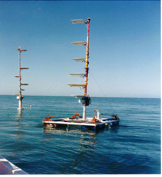
In order to estimate the duct height instrumented buoys (see Figure 1) capable of measuring the air temperature, humidity and air pressure at several heights were constructed and subsequently used in various locations. The duct height is determined by model-dependent parameter-estimation techniques. Several experimental campaigns have been carried out in various locations; including , , Osprey Reef, the , the Western Pacific, and the Gulf St. Vincent (). From temperature, humidity and pressure readings the modified refractive index, M was calculated and the duct height was estimated by a least-squares fit to an evaporation duct model.
The diversity in duct heights due to seasonal and geographical changes is evident from Figure 2 where the percentage of time that a given duct height is exceeded, is plotted as a function of duct height. Three examples are given: 1) The equatorial regions of the , 2) The and 3) Lucinda Qld. The graphs are based on 168 hours of data collection at a sampling rate of one sample per 12s.
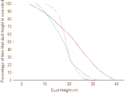
The percentage of time that a given duct height is exceeded is plotted here as a function of duct height for three different regions. The solid curve is for the equatorial West Pacific in February (far left at 100%), the dashes and dots, curve is for the Coral Sea in May (far right at 100%) and the dashed, curve is for the coastal region around Lucinda, Queensland in October (centre at 100%).
The International Telecommunications Union (ITU) provides a number of Recommendations from which calculations of propagation relating to interference can be made. The Recommendation of interest in the case of signals in X or Ku band is ITU R Rec P-452. This recommendation contains formulae for the calculation of the incidence of anomalous propagation (ducting) and path loss within a duct. For the zone where our measurements have been undertaken, Rec-452 estimates duct incidence at 24%. However, during clear-air conditions, there is a much higher evaporation duct incidence over warm tropical waters as shown in Figure 2.
Radio-wave propagation experiments
We have conducted a number of trans-oceanic radio propagation experiments since 1998 and the data from these measurement campaigns is being processed. Of particular interest to military radar and SIGINT operations are the results of a long-distance experiment carried out in July 1999.
In this case both transmitter and receiver were inside the duct and the RF wave no longer propagates according to the ‘square rule’, that is with a 20log(df), (where d is distance and f is frequency) loss factor, instead it is trapped as if in a waveguide. A depiction of this can be seen in Figure 3.
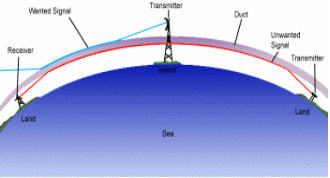
The radio path was established from Toolakeah beach, 20 km north of Townsville in , to the Bulk Sugar Terminal at Lucinda, north of Ingham. The overall path length was 72.2 km. The transmitter was positioned on the sand dunes at Toolakeah with an effective transmitter height of 4-m AMSL. The transmitter consisted of a 20-mW YIG source tuned to 10.6 GHz and a 0.6-m 28-dBi parabolic antenna.
The receiver was positioned at the end of the Bulk Sugar Loading Jetty at Lucinda which extends approximately 6 km from shore and provides an excellent platform for over ocean studies. The receiver consisted of an array of receivers each having a 16-dBi slotted guide antenna and a 55-dB LNC. These were connected to a switching matrix from which the signal was sampled at approximately 90-s intervals for each array element.
Using bulk parameters (that is, course measurements of air and sea-surface temperatures along with humidity), duct heights varying from 29m during the day to 10m at night were calculated.
Figures 4 and 5 show a simulation of propagation inside a 29-m duct (day) and a 10-m duct (night) using a program developed by the US Navy called AREPS [3]. AREPS allows a user to study the effect of ducting when duct heights are known or where only bulk parameters are know. Our work has so far shown that this and models like it, based on a method known as the parabolic equation method (PEM) are accurate enough to give warning of anomalous propagation conditions.
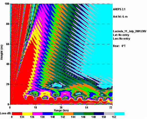
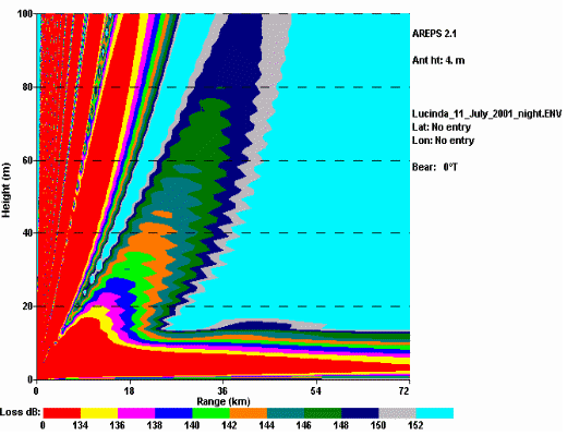
Of particular note in both figures are the extended range of propagation, seen most clearly in Figure 5, and propagation ‘black holes’ shown clearly in Figure 4 as lighter round areas in close to the transmitter at a height of about 10m. A target in one of these areas, such as an incoming missile or hostile small vessel, would suffer a greater chance of detection failure. Wind speed affects duct height and reflection from the sea surface [2]. The propagation shown in Figures 4 and 5 are for light wind and do not take into account sea roughness. It can be theoretically shown using programs such as AREPS and TERPEM [4] that the incidence of ‘black holes’ reduces with a rough sea. We are yet to confirm this physically through experiment.
A duct acts as an angular filter. Only radio waves propagating above about 0.5° are trapped in the duct so, as sea-surface roughness increases with wind-speed, energy can be lost from within the duct and propagate above it.
Received signal strengths for the long-distance experiment from four array elements for a 24-hr period are shown in Figure 6. These signal powers have been calibrated for system errors. Of interest is the strongest signal, received at the second lowest element at 4.5-m AMSL.
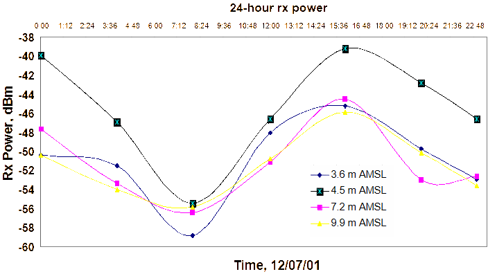
A strong link between diurnal variations in the sea-land breeze system, air temperatures and duct height and strength has been suggested in [5] and is supported in the literature. This behavior is evident in the diurnal variation of received signal strength across the array.
The powers in Figure 6 are the result of a path loss in the range 140–160 dB.
ITU Rec P-452 estimates the path loss for this path at 135 dB which slightly underestimates the path loss seen on the day but is reasonably accurate within the system errors present.
ITU studies affecting maritime radar systems and the phalanx close in defence system
Phalanx is a fast-reaction, rapid-fire 20-mm gun system capable of providing naval ships with a "last-chance" defence against anti-ship missiles and littoral-warfare threats that have penetrated other fleet defences. Phalanx automatically detects, tracks and engages anti-air warfare threats such as anti-ship missiles and aircraft and an emerging new littoral warfare threat comprising small, high-speed surface craft, small terrorist aircraft, helicopters and surface mines. Phalanx accomplishes these engagements via an advanced search-and-track radar system operating between 13–14 GHz integrated with a stabilized, forward-looking infra-red (FLIR) detector. This integrated FLIR provides Phalanx with a unique multi-spectral detect and track capability for littoral warfare threats and dramatically improves the existing anti-air warfare capability. Phalanx is the only deployed close-in weapon system capable of autonomously performing its own search, detect, evaluation, track, engage and kill-assessment functions. Phalanx also can be integrated into existing combat systems to provide additional sensor and fire-control capability. [9]
Phalanx shares much of its frequency band with the fixed satellite service (FSS). In this band the FSS transmits from the Earth (uplink) and could, if many terminals were operated around the coast, cause considerable interference to Phalanx systems.
When the FSS first sought entry into the band the ITU undertook studies to ensure compatibility with radar terminals. The studies resulted in the current constraint on FSS use of the band to Earth stations with antennas no smaller than 4.5-m in diameter had been imposed with a view to limiting the number of FSS Earth stations likely to be deployed, and thus limiting the interference to radar terminals.
The ITU assessed interference into radiolocation systems in terms of a decrease in probability of detection, which leads to a decrease in radar range and/or target tracking ability. Taking into account these factors, the ITU has concluded that the appropriate criterion to ensure the protection of maritime and land mobile radars would be a Interference/Noise ratio of –6 dB, corresponding to an interference power level of –133 dBW in a bandwidth of 10 MHz at the receive output flange of a radar antenna.
A proposed sharing criterion to satisfy the above radiolocation protection level for FSS Earth stations with a diameter less than 4.5m, would be a single entry interfering pfd level of: for maritime radar: X dB(W/(m2 · 10 MHz)) not to be exceeded for more than Y% of the time produced at 36m above sea level at the normal baseline (low-water mark) as defined in UN Convention on the Law Of the Sea. [7]
Problems occur, however, when we use Rec P-452 to calculate the percentage of time interference will be present. Using calculations in the Recommendation duct incidence is 24%, we have shown it to exceed 90% in most cases. In the opinion of the authors and for the tropical littoral zone within latitude 25° of the equator it should be assumed that ducts will always be present. While this is slightly conservative it would ensure the continued viability of the Phalanx system and ensure the incidence of interference is not underestimated.
Also of note is the baseline of 36m mentioned in the report. While this was intended to provide protection for units mounted high on an aircraft carrier’s structure it again does not take into account ducting.
Referring again to Figure 3, the scenario of the 36-m radar receiver is depicted by the tall tower in the centre of the duct path, above the duct. From Figure 6 we see that increased height does not mean increased signal strength in the duct. It is possible therefore that, if actual measurements were made, both the interfering signal strength and incidence from low-mounted coastal FSS would be significantly underestimated as only the scattered signal would be seen.
In Figure 2 we see the incidence of ducts higher than 36m is between about 5% and 25% (the latter figure is of interest as it is what Rec P-452 predicts). So, in tropical littoral regions, the authors believe that again, the incidence of interference to Phalanx systems mounted on smaller vessels, such as the Australian Navy’s Anzac Class Frigate, will be significantly underestimated.
Conclusions and future work
It is evident from these and other studies that naval commanders need to be at least aware of the effects of propagation inside the evaporation duct and how they affect radar and other signals systems operating above about 1 GHz.
The viability of Phalanx radar systems operated in the band 13.75–14 GHz is under threat because the ITU Recommendations used in sharing studies under-estimate the prevalence of ducts in the tropical littoral. A significant amount of work is needed on propagation over tropical oceans which can be fed back to update ITU Recommendations. The currently available information is inadequate to properly study sharing between the FSS and radar where the interfering wave propagates over oceans.
[1] K. Andersen, “Radar Detection of Low-Altitude Targets in a Maritime Environment”, IEEE Transactions on Antennas and Propagation, Vol. 43, No. 6, June 1995.
[2] A. Kerans, et al, “Evaporation Duct Statistics Around Australia and the West Pacific”, Proceedings of AP2000, Davos , 2000.
[3] SPAWAR Advanced Refractive Effects Prediction System (AREPS) program, www.sunspot.spawar.navy.mil.
[4] M. Levy, TERPEM: Parabolic Equation Methods for Electromagnetic Wave Propagation, IEE Press.
[5] A. Kulessa, M. Heron, and G. Woods, “Temporal Variations in ”, Proceedings of the Workshop on Applications of Radio Science, pp. 165-170, 1997
[6] J. Hermann and A. Kulessa, “Assessment of the Role of Signal Fluctuations and Refractive Structures in Microwave Systems Performance”, DSTO-RR-0191, 2000.
[7] E. Gossard, “The Height Distribution of the Refractive Index Structure Parameter in an Atmosphere Being Modified by Spatial Transition at its Lower Boundary”, Radio Science, Vol. 13, pp. 489-500, 1978.
[8] E. Ryzner and J. Bartlo, “Dependence of Cn2 and CT2 in the Atmospheric Boundary Layer on Conventional Meteorological Parameters”, USAF Geophysical Laboratory, Report no. AFGL-TR-86-0013, 1986.
[9] http://www.chinfo.navy.mil/navpalib/factfile/weapons/. wep-phal.html
[10] ITU-R CPM Report 2002. www.itu.int.
Andrew Kerans is Principal Engineer, Space Systems with the Australian Communications Authority. He obtained his BEng from the in 1993 and his MEngSc from the , in 1998. He is currently pursuing a PhD in Engineering at , specialising in low-angle microwave propagation over oceans. Mr Kerans has previously worked with Telecom and the Australian Defence Department. He is a Senior Member of the IEEE. He can be contacted at andrew.kerans@aca.gov.au.
Andy S. Kulessa is a Senior Research Scientist within DSTO. He was born in and received his scientific training at universities within and the . At DSTO, his work has included the development of instrumentation to measure microwave ducting, the characterisation of clear-air tropospheric propagation phenomena, and modelling of electronic warfare systems performance. He has published scientific papers, research reports and conference papers in the field of radio science.
Graham S. Woods received the BE (Hons I), MEngSc and PhD degrees in electrical engineering from James Cook University, Townsville, Australia, in 1984, 1986 and 1990 respectively. He is currently acting Head of Electrical Engineering at . His current research interests include microwave sensors and instrumentation, six-port measurement systems, near-field antenna measurements and over-ocean radio propagation prediction.
John A. Hermann is a Principal Research Scientist within DSTO. He received his scientific training at universities within and the . He specialises in the application of mathematical methods to physical problems, and has published a significant number of scientific papers, research reports, conference papers and review articles within the general areas of beam propagation, nonlinear optics and RF propagation physics.