
Volume 6, Number 2, July 2003
Aspects of Trans-Horizon High-Frequency Communications with Helicopters
- 1 Antuition Enterprises, 4 Kipling Street, Moonee Ponds, Victoria, Australia 3039.
Abstract
This paper discusses issues related to trans-horizon high-frequency (HF) communications from low-level airborne platforms; specifically the Australian Army’s Black Hawk helicopters. It discusses work completed and in-progress in this area, both privately and at the Australian Army’s Land Engineering Agency (LEA), and brings together a number of communications-related aspects including HF propagation, antenna aspects and frequency and altitude management, all of which need to be properly managed to obtain the best HF communications from helicopters. The possible use of genetic evolution to improve antenna design is also briefly discussed.
Background
High-frequency (HF) communications have been with us for over 100 years. Before the age of global satellite coverage, the HF band was essentially the only way of providing long-distance radio communications. Because of the nature of the propagation environment, higher-frequency communications systems, in their simplest forms, are limited to line-of-sight (LOS) ranges. It is therefore not surprising that HF became synonymous with long-range coverage. However, if properly managed, HF can also cover the line-of-sight range using ground wave, as well as providing coverage past the horizon using sky wave. The key to this is proper management—both of the communication assets and the environment. For example, inadequate management and understanding of the intricacies of HF communications has led to the popular belief that the use of HF communications from a helicopter can be a waste of time. There is an expectation that it should provide the same quality and be as simple to use as very high frequency (VHF) communications—just press and talk. This, however, is not the case.
Because of their flying capabilities, helicopters are often involved in low-level operations, spending much of their flying time at altitudes between the treetops and a few hundred feet, and at ranges up to a few hundred kilometres from their base. HF communications, (3 to 30 MHz), are generally found to be reliable up to the horizon. But then so are VHF communications (30 to 300 MHz), which are generally preferred because of lower noise performance, higher bandwidth, better modulation scheme (FM rather than AM), and simpler operation. However, because VHF is essentially limited to a LOS path, it is not available at any significant distance past the horizon or when low altitudes lead to terrain screening. It is then that HF must be used and where the problems begin. It is common knowledge that HF or ‘short-wave’ communications are capable of sending signals around the world. Why then is HF communication so unreliable at relatively short distances of a few hundred kilometres?
The problems of helicopters and HF communications were being investigated by the author at the Australian Engineering Development Establishment (EDE), now Land Engineering Agency (LEA), as far back as 1995 for both Black Hawk and Sea Hawk although, for the most part, the results were not acted upon. Recently, however, operations in “difficult terrain” have once again demonstrated the problems in obtaining reliable HF communications at relatively short distances. This provided the impetus to task LEA to investigate the operational aspects of HF communications from low-level airborne platforms and the impact of different antenna systems. This paper addresses the nature of HF communications, electromagnetic modelling work performed privately and at LEA, and well as some of the work being undertaken by LEA to investigate the antenna and procedural aspects of the problem.
HF communications
Ground wave
HF communications can be supported by ground-wave propagation over LOS range, which is a function of the antenna height and the nature of the terrain. From geometric considerations, the line of sight to the geometric horizon is a distance of:
(1)
where dgeo is the distance to the geometric horizon in kilometres and h is the antenna height in metres above the earth.
The radiation does not travel in a perfectly straight line, however, and is bent gently toward the earth due to the refractive index profile of the atmosphere. More specifically, over a smooth earth and for the refractive index gradient of the International Telecommunications Union (ITU) standard atmosphere [1] the distance from the aircraft to the radio horizon is:
(2)
where drad is the distance to the radio horizon in kilometres and h is the antenna height in metres above the earth.
Figure 1 illustrates the difference between the geometric and radio horizons.
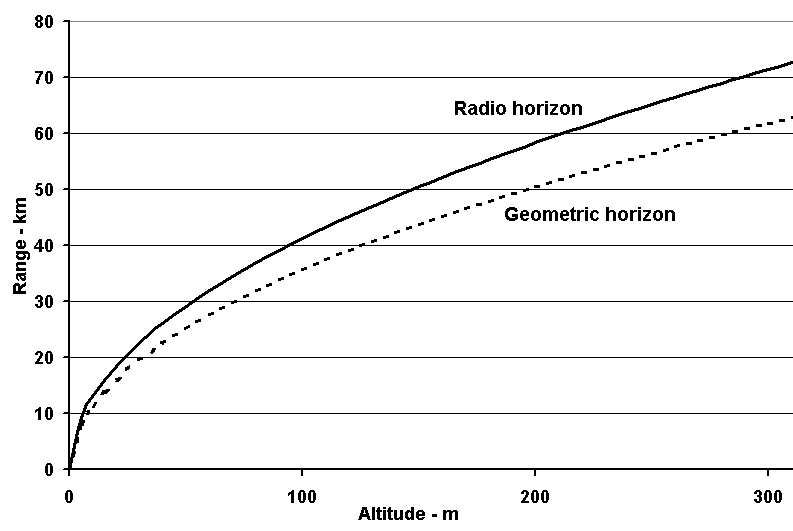
While the radio horizon predicts propagation range over a smooth earth, less coverage will generally be obtained over irregular terrain, as prominent terrain features interrupt the propagation path. While in any particular case, the range reduction will be a function of the height and extent of the terrain features, the geometric horizon can be considered a useful guide (Figure 1). Whatever the range, to ensure the greatest signal strength at the receiver, for LOS communication antennas at both ends of the circuit must have the majority of their available gain directed at low take-off angles.
Signals radiated near the earth can excite a surface wave. While the horizontally polarised component is rapidly attenuated, vertical polarisation can provide useful communications. Over poorly conducting soils the range is limited to a few tens of km. However over a smooth sea, useful ranges up to several hundred km are possible. While offering a potential advantage for maritime operations, the limited vertical extent of a helicopter antenna and airframe generally precludes efficient radiation of vertical polarisation.
Sky wave
HF communication beyond the radio horizon or past screening terrain is only possible by sky wave, which uses the ionosphere, an ionised region of the atmosphere comprising a number of layers, to refract the signal back to earth. The layers are typically at about 80 km (D layer), 110 km (E layer), and upwards from about 150 km to several hundred kilometres above the earth (F1 and F2 layers). An “F3” layer has recently been reported [2], but this is not discussed in this paper. Over the HF band, the D layer is responsible for attenuation rather than refraction of the signal. Layers vary considerably with location, time of day, season, the 11-year sunspot cycle and with the 27-day rotation period of the sun. However, for path geometry considerations, at any particular time and path the ionosphere can be considered as a reflecting surface with an effective reflection height. From geometric considerations, for best performance at short ranges it will be seen antennas at both and of the path require the majority of their gain at very steep angles, approaching the vertical. Communication using these high-angle paths is referred to as near-vertical-incidence sky wave (NVIS).
Each layer of the ionosphere has a maximum useable frequency (MUF) above which the signal no longer returns to earth, but passes through the ionosphere. For vertical incidence this is called the critical frequency fc. Neglecting the curvature of the earth, the relationship between MUF and fc is:
(3)
where Φ is the angle of incidence of the signal path at the reflecting layer (see [3]), and this angle determines the path length. As losses increase for frequencies below the MUF, path losses for short path lengths (that is, high angles of incidence) will be a minimum for frequencies close to but less than fc. Longer path lengths use lesser take-off angles, and the reduced angle of incidence allows use of correspondingly higher frequencies. The maximum ground wave range is controlled by terrain and antenna height, and minimum NVIS range by the frequency (≤fc), as well as there being sufficient antenna gain at high take-off angles. Between these regions there is often a “skip zone”, where HF communication is not possible. For the short-range operations being considered the skip zone must be eliminated or minimised.
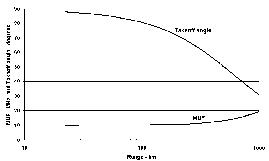
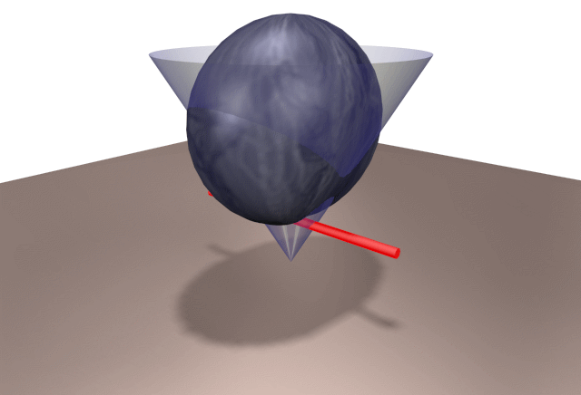
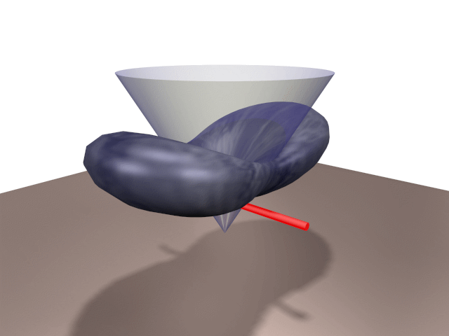
From Figure 2, it can be seen that for sky-wave communications via the F layer, assuming a “typical” effective reflection height of 300 km, take-off angles at or above 60° are needed for ranges less than about 200 km. For best NVIS performance the antennas at both ends of the circuit must have the majority of their gain above this angle. And because the total gain from any antenna is fixed, this implies lower gain at lesser angles—such as those needed for LOS communications (or long-range sky wave). Thus an antenna that is good for NVIS will generally be poor for LOS, and conversely, an antenna that is good for LOS will generally be poor for NVIS. A criterion for good NVIS antenna might thus be based on the amount of its total gain that lies with an upper cone of (say) 30° from the vertical. A corresponding criterion for LOS performance would be the gain contained in the lower 30° cone. Figures 3, and 4 show the “NVIS cone” on the radiation patterns from a horizontal dipole. Figure 3 is for a dipole height of 1/4 wavelength, Figure 4 is for 1/2 wavelength.
Figures 5 to 8 are taken from an ionospheric training tool under development by the author. Based on an electron-density profile in the ionosphere, the refractive-index profile for the selected frequency is calculated. From this ray paths for an isotropic antenna at two-degree take-off angles are plotted. A calculated vertical ionogram showing the effective heights of the various layers as a function of frequency is also displayed.
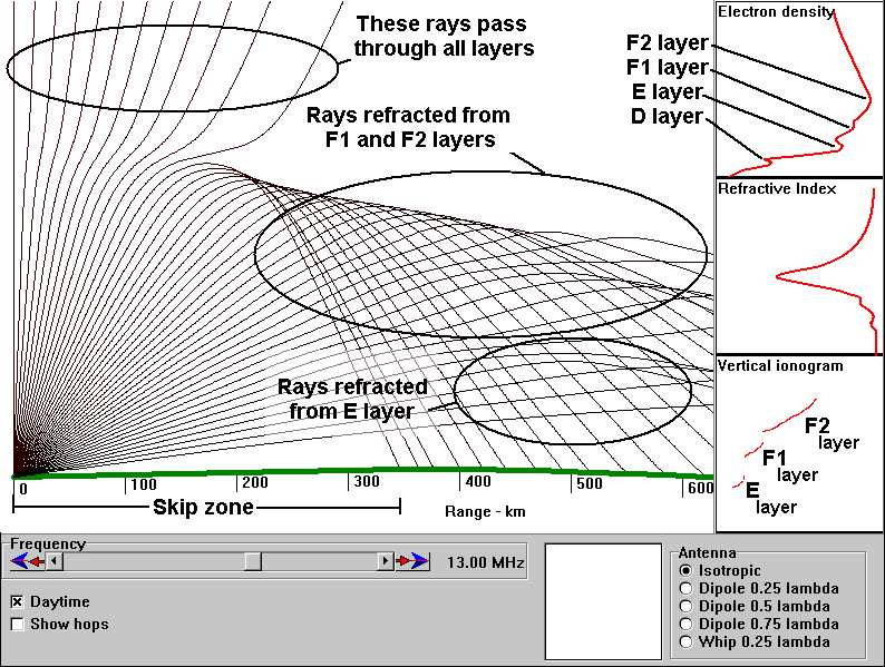
Figure 5 shows rays from an isotropic antenna with a typical daytime ionosphere. The critical frequency has been set to 12 MHz, and the operating frequency is 13 MHz. As a consequence, the high-angle ionospheric paths do not return to the earth, resulting in a skip zone of some 340 km. Lower angle paths are returned by the F2, F1 and E layers.
Figure 6 shows the ionospheric paths available for a lower frequency (12 MHz), which indicates no skip zone. However, the impact of the antenna pattern must also be considered.
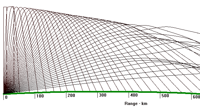
Figure 7 shows the available paths using a dipole 1/4 wavelength above the ground (the antenna of Figure 3). This, together with the correct frequency choice allows NVIS operation.
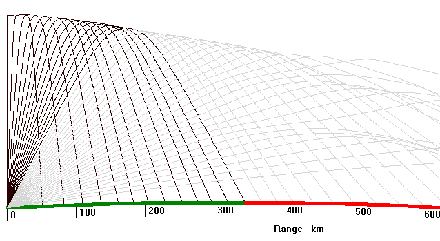
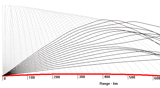
Figure 8 shows the result of poor antenna choice (the antenna of Figure 4). Even if the ionosphere can support high-angle paths, with no high-angle gain a skip zone will result. Proper choices for antenna patterns at both ends of the circuit are essential for communications. For ground-based antennas, this implies a choice of the correct antenna type and configuration. For airborne antennas, the problem is more complex as the radiation pattern changes significantly with altitude. This effect is most noticeable at altitudes up to a few wavelengths—the altitude where helicopters spend much of their time. The pattern changes arise from the interaction between the “direct” path (via the ionosphere) and that reflected from the ground. For each half-wavelength change in altitude (40 ft at 10 MHz), there will be cyclic variation in antenna gain, and a corresponding variation in received signal strength. And the range of variation will depend on how much gain is directed towards the ground.
The antennas
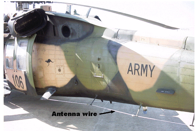
The current Black Hawk antenna is an unterminated wire, lying substantially parallel to and about 250 mm from the fuselage (see Figure 6). This is referred to here as the “wire antenna”. The proposed replacement antenna has generally the same geometry as the wire antenna, but is a tube, and terminates on the fuselage, rather than being unterminated. Because of its appearance, is known as a “towel-rail” antenna. Below the first resonance (about 16 MHz), its impedance is inductive rather than capacitive and the consequent impact on antenna matching must also be considered in the system design. One solution is to fit a series capacitor to tune the antenna, leaving the original “inductive” antenna tuning unit (ATU) intact (including its losses). The other is to fit a purpose-built ATU unit, which would be predominantly capacitive below the first antenna resonance. As losses in the tuning capacitors are almost certain to be significantly less than those of the inductor of comparable impedance magnitude, the losses in a “capacitive” ATU will be correspondingly less.
Model creation
To provide a baseline against which the towel-rail antenna could be compared, a detailed model of the Black Hawk fuselage was created in AutoCAD. An accurate 3D drawing of the fuselage was developed and used as a framework on which to manually create a triangular “wire” mesh. This methodology is described in [4]. This was checked for model integrity using the methods of [5], and for completeness in 3D Studio by viewing it as a surface model. The wire and surface models are shown in Figure 10. The mesh size was kept as coarse as possible consistent with maintaining the fuselage shape, and providing sufficient spatial resolution in the regions adjacent to the antenna, particularly around the drive and termination points. To allow later investigation of rotor modulation effects, the rotor mast was designed allowed the main rotor to be rotated in 22.5º increments with no change to the fuselage geometry. For this investigation the four main rotor blades were aligned at 45º to the centreline of the fuselage. A range of attachment points was also provided so that the towel-rail antenna could be modelled in different configurations without changing the fuselage model.
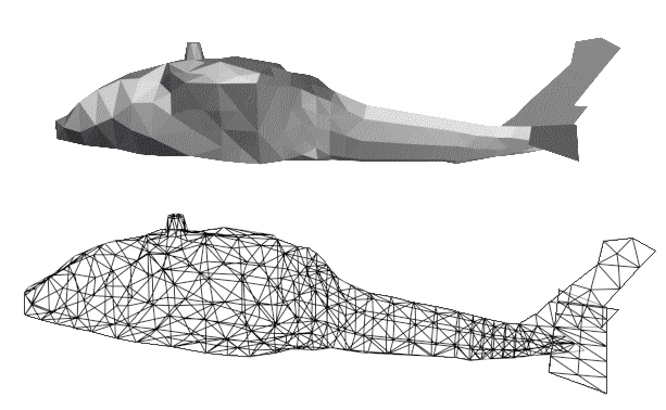
So that the wire mesh model of the fuselage would behave as a surface, the “equal area” rule was applied. This rule requires that the diameter of each wire to be assigned so that the sum of the surface areas of the wires bounding a triangular mesh is equal to the area of the mesh. As most wires are shared by two meshes, compliance with this rule requires some ingenuity to satisfy the requirements for adjoining meshes. An iterative procedure was developed to assign wire diameters, terminating when the maximum discrepancy in area was less than 1%. At this stage all wires were assumed to be perfect conductors.
Modelling runs
A number of initial runs were made in NEC2D, during which the performance of the model was examined at frequency extremes and at low altitude, the conditions most likely to lead to modelling problems. Model performance was monitored by logging the antenna efficiency, radiated power, and by comparing the average radiated power to the computed antenna drive power. After some fine-tuning, performance was considered satisfactory down to about 3 MHz, and at altitudes down to about lambda/10 (about 33 ft at 3 MHz). A final fuselage model consisting of 729 triangular meshes was adopted. This translated into 1163 wires, additional “non-mesh” wires being added for the antenna and rotors. While this complexity might seem overkill, it was found necessary to ensure that the model performed adequately across the required frequency range, as well as extending it beyond 30 MHz for other work. Structure losses were then included by designating antenna components as copper, and the fuselage and rotor as aluminium.
The computed free-space antenna impedance was compared with that measured on a Black Hawk on the ground (Figure 11). As the towel-rail antenna had essentially the same geometry as the wire antenna, it was simulated by shorting the wire antenna to the fuselage at its end, and measurements taken. These data were compared with the modelled towel-rail impedance (Figure 12).
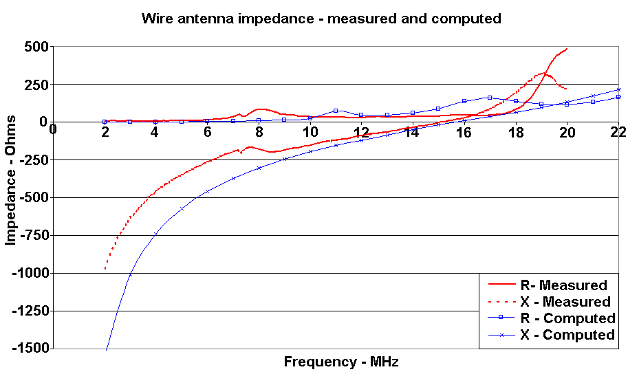
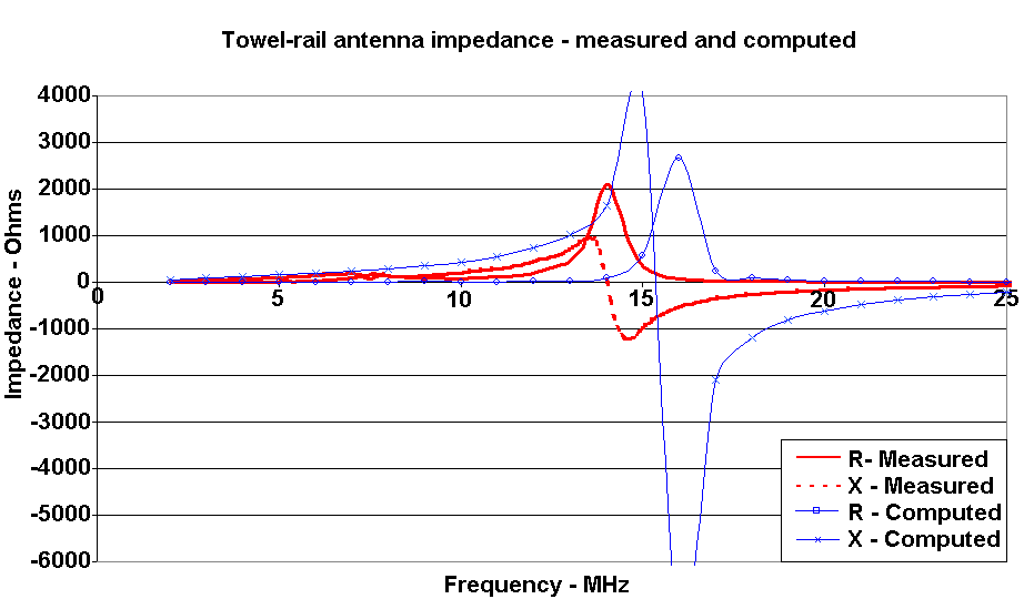
The poor correlation between measured and computed antenna impedances is disappointing. In both Figures 11 and 12, the modelled resonant frequencies are up to about 2 MHz higher than those measured. This may be a consequence of the models being run with a free-space environment, while the measurements were taken with the helicopter on the ground, which would provide additional capacitive loading. If the model could have been run close to the ground, or the impedance measurements taken in flight, the correlation may have been better. The Q of modelled resonances is higher than those measured. This may result from the “perfect” fuselage bonding assumed in the model, a situation that probably did not exist in the helicopter. There may be some justification for degrading the model conductivity to include this effect.
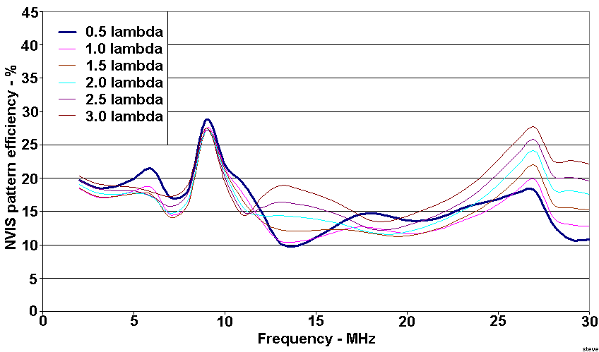
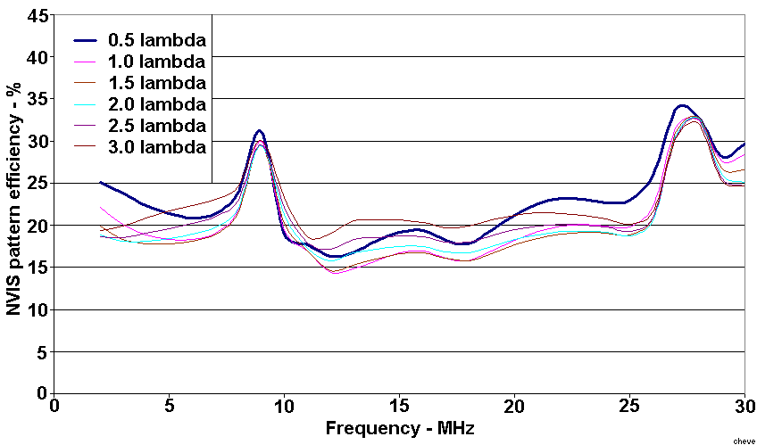
To shed some light on the variation of angular gain distribution with altitude runs were made in 1 MHz steps from 2 MHz to 30 MHz. These were done at 1/8 lambda altitude steps from 1/8 to 3 lambda. The results were processed to extract percentage of total gain above a 60º take-off angle (an “NVIS efficiency”) and below 30º (“long-range efficiency”). Wire antenna results for altitudes of odd and even quarter-wavelengths are presented in Figures 13 and 15 and for the towel-rail antenna in Figures 14 and 16. Figures 17 and 18 compare the NVIS and long-range pattern efficiencies for the wire antenna at altitudes of 1/4 lambda and 1/2 lambda.
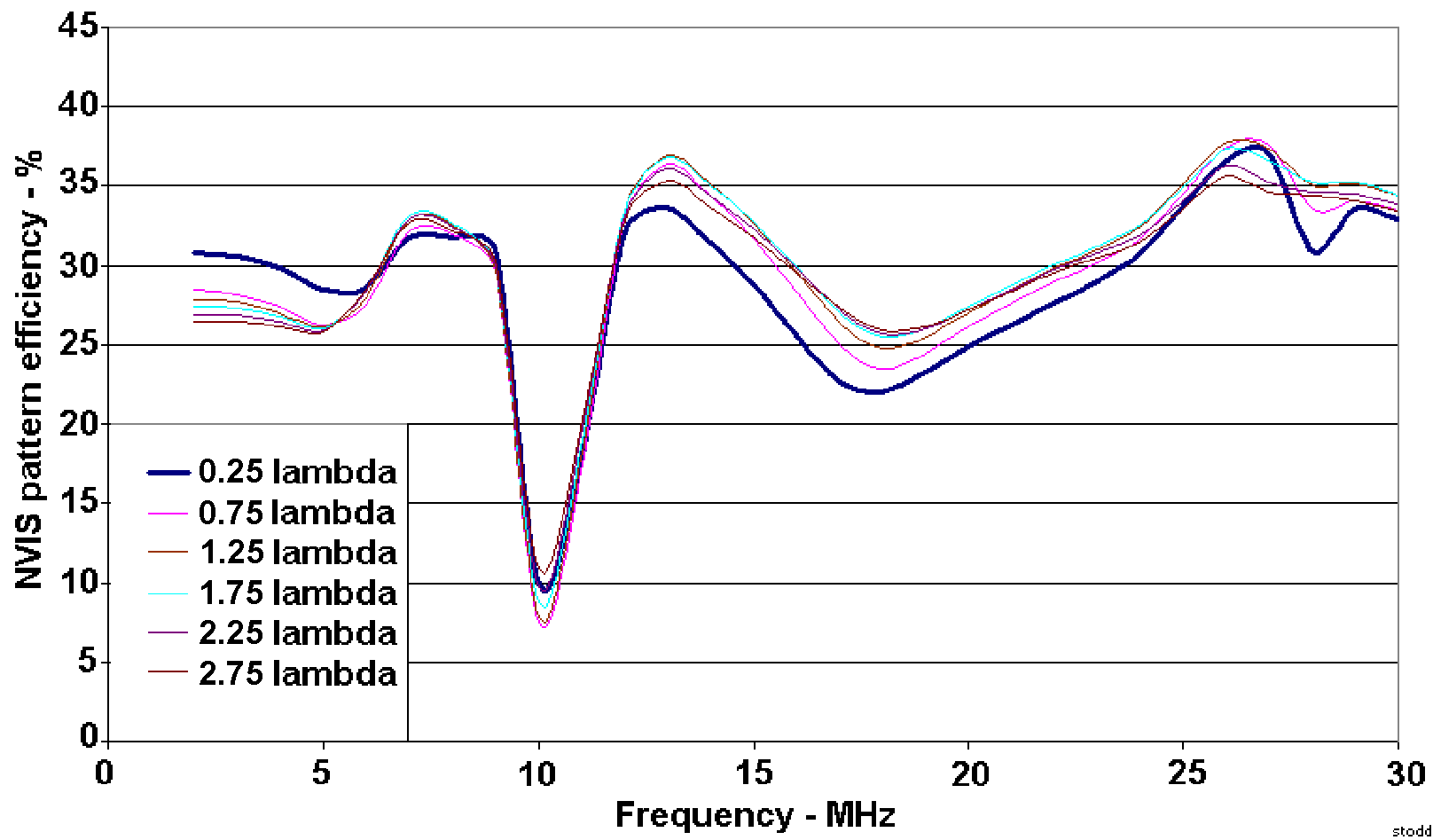
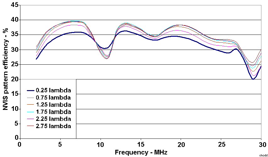
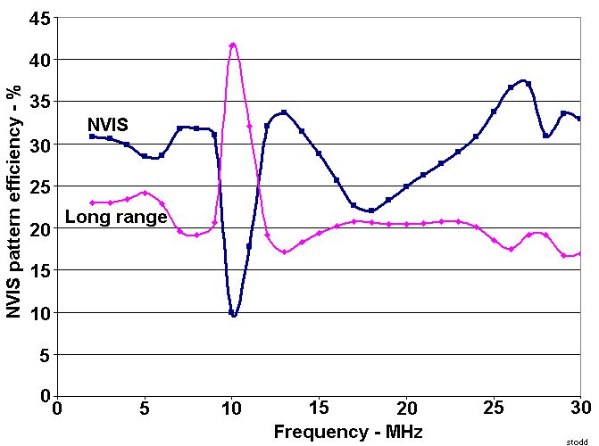
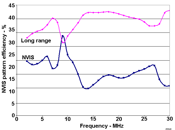
While the greater near-vertical gain for 1/4 lambda than for 1/2 lambda was expected, the dramatic inversion around 10 MHz was not. A similar, although lesser, effect was exhibited by the towel-rail antenna. Examination of fuselage current distribution revealed that between 9 MHz and 11 MHz there was a significant redistribution from the fuselage to the rotor and to a lesser extent to the tail; in other words, an airframe resonance. Similar effects have been reported [6] on a CH-149/Cormorant helicopter with a hybrid antenna (a towel-rail antenna with a selectable shorting link to the fuselage quite close to its drive point). As this occurred at similar frequencies with an airframe of comparable size but with a very different antenna, the effect would seem to be an artefact of the airframe rather than the antenna.
There are several possible contributors to this resonance. Neglecting end effects, the Black Hawk fuselage length of 15.5m corresponds to a 1/2 wavelength at 9.7 MHz, while the rotor diameter of 16.4m gives 9.1 MHz. The total fuselage+rotor length of 19.7m gives 7.7 MHz. The antenna wire length of 4.5m corresponds to a 1/4 wavelength at 16.6 MHz, and apart from providing the excitation of the fuselage, does not appear to play a significant part in the resonance.
Discussion
To investigate the changes in current distribution, a tool was developed to display current as a colour overlaid on a 3D drawing of the airframe mesh. The display relies heavily on colour and does not reproduce well in black and white document. For this paper Figures 19 and 20 have been produced to show a small part of this effect—the frequency variation of computed current at the root of the main rotor blades for both antennas, and normalised to the antenna current.
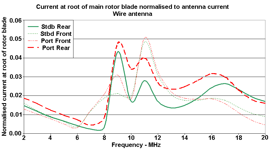
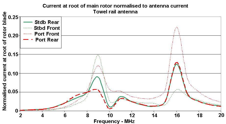
Figures 19 and 20 show a significant excitation of the main rotor as the frequency passed through about 10 MHz. In both cases there is an increase in coupling from the antenna in the 9 to 11 MHz range, as well as around 16 MHz. Note that the two graphs are of different scales and that coupling is considerably greater for the towel-rail antenna. Similar large redistributions of current have been reported for the CH-149 helicopter at frequencies around 10 MHz [6]. Indeed, analysis of fuselage and antenna current distributions indicates that at many frequencies the airframe contributes more to the radiated energy than the antenna itself. This emphasises the need to consider the radiator as the whole system, not just the antenna itself. The redistribution of currents with frequency will also modify the radiation phase centre—the “centre of radiation” with respect to the aircraft. Thus the “antenna” may not always be at the same “altitude” as the aircraft.
The radiation pattern of any particular antenna can be considered as the vector sum of its free-space pattern and that reflected from nearby objects. In a lossless environment, the total gain remains constant; any increase in gain in one direction can only be obtained at the expense of gain in another. The near vertical radiation (or gain) is the vector sum of the upward radiation and the downward radiation reflected from the ground, including its phase change on reflection. If these two components are in phase, such as occurs when the antenna altitude is an odd quarter wavelength, there will be an increase in vertical gain at the expense of that at lower angles. If they are out of phase, (antenna altitude is an even quarter wavelength) there will be a reduction in vertical gain, and a corresponding increase in gain at lower angles. For odd quarter wavelengths, a reduction of either upwards or downwards gain which is caused, for instance, by a frequency change, and which reduces the upwards or downwards gain, will reduce the gain available for NVIS, and enhancing that for LOS and long range sky-wave performance. For even quarter wavelengths the opposite occurs; a reduction in either the upward or downward gain will enhance the NVIS performance at the expense of the long-range performance, as it will reduce the effect of cancellation.
The communication difficulties with Black Hawk, and indeed other helicopters, arise with NVIS rather than long-range communications. Since the upper frequency limit of NVIS operation, even with the present moderate sunspot activity, is not more than about 13 MHz, processing time was saved by limiting the upper frequency to 20 MHz, thus still giving some useful data for long range communication. Runs were made at altitudes in 20-ft steps from 20 to 500 ft. They were performed in batch mode using a modified version of NEC-2 that accepts file names as command line arguments, thus allowing the efficient unattended processing of large numbers of runs. The Sommerfeld-Norton ground model was invoked for altitudes less than 1.5 wavelength, and the reflection coefficient approximation for altitudes above that. Execution times with a 600 MHz Pentium III with 128 MB RAMdisk averaged 42 minutes for each frequency/altitude combination, a batch of 19 frequencies and 24 altitudes taking just on 15 days to complete.
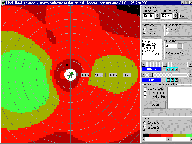
Data from these runs was compressed using techniques derived from those described in [7], reducing the NEC output files from each run from 250 Mbyte to just over 700 kB. A viewer was written to examine the performance of the various antenna configurations, displaying antenna gain as area coverage footprints. The ionosphere was assumed to be “well-behaved”, characterised by a critical frequency and effective reflection height. NEC processing assumes a flat earth. While both these simplifying assumptions become less valid as range and altitude increases, they were felt to be sufficiently realistic to provide an understanding of the variation of antenna NVIS performance. Figures 20 to 23 show gain footprints over a ±900 km square area, with antenna gain displayed in 3 dB steps. Figures 20 and 21 are for the wire antenna at 9 and 10 MHz, and Figures 22 and 23 are for the proposed towel-rail antenna for the same frequencies. In all cases the altitude was set to 60 ft, and the helicopter heading (shown in the centre of the screen) to 30º (1 o’clock).
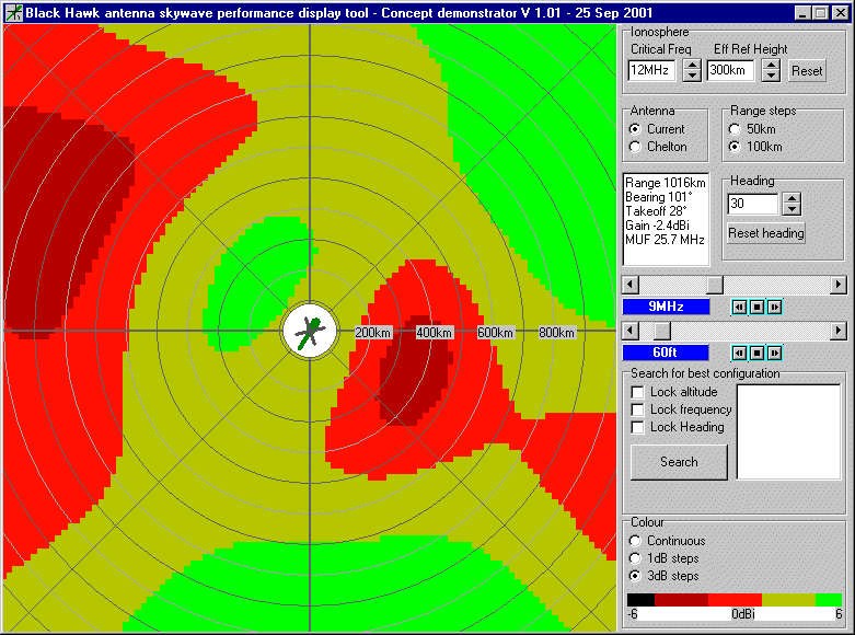
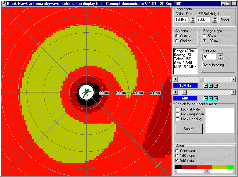
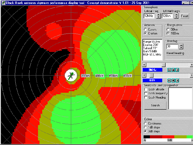
Figures 21 to 24 show the dramatic change in area coverage caused, in this instance, by changing frequency from 9 MHz to 10 MHz. This is within the frequency range where the most significant change in vertical radiation occurs with frequency, which arises from significant current redistribution on the airframe—a result of rotor and/or airframe resonances. Similar effects, particularly for NVIS operations, can occur with small altitude changes, resulting from changes of path length difference of the direct and ground-reflected component—that is the interaction between “direct” and “reflected” components of the radiation pattern. For the wire antenna at a frequency of 12 MHz (lambda/4 ≈ 20 ft), the antenna gain in the NVIS coverage area varies cyclically by 12 to 15 dB for each 20 ft change in altitude. The towel-rail antenna exhibits similar behaviour, but varies by about 8 to 12 dB. It is not surprising that without knowledge of this behaviour, or any procedure to manage such gain variations, HF communication from helicopters retains its reputation for unreliability.
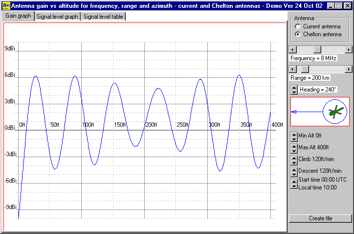
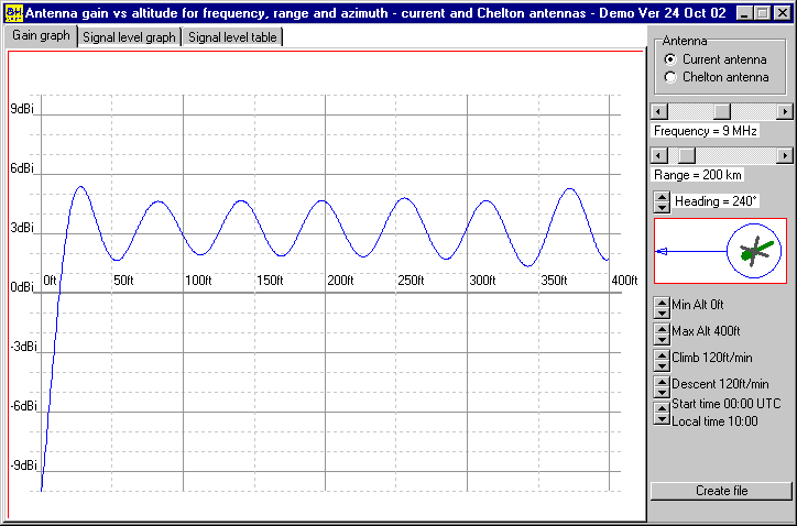
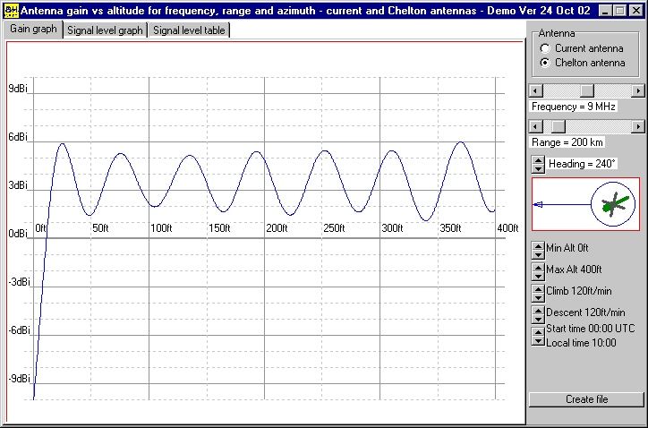
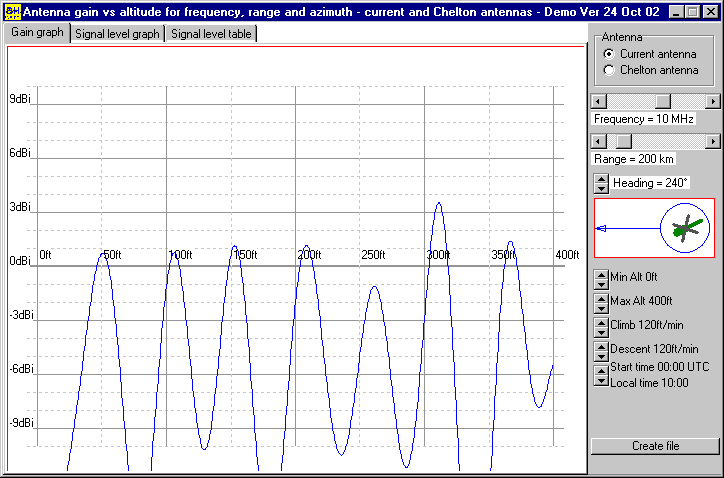
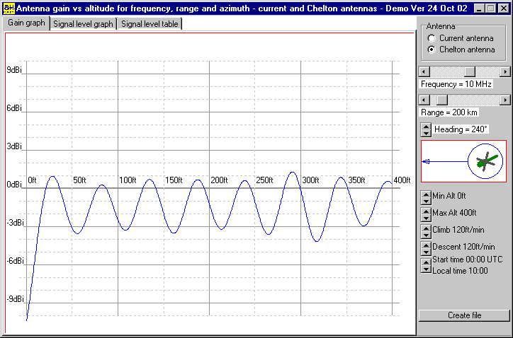
Another tool was developed to display the variation in available antenna gain with altitude for given frequency, range and azimuth. This gives additional insight into the effects of altitude on antenna gain and its impact on communications for a given path. Figures 25 to 30 show the variation of available sky-wave antenna gain to a ground station 200 km west of the aircraft, with an aircraft heading of 240º for wire and towel-rail antennas
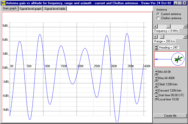
These figures illustrate the range of antenna gain variation that might be expected as a helicopter climbs from ground level to 400 ft. While some frequencies (such as 9 MHz) exhibit gain variations of only a few dB, excursions of almost 20 dB are predicted at nearby frequencies (such as 8 MHz and 10 MHz), particularly for the wire antenna. Overall the towel-rail antenna seems to be better behaved. It should be noted that gain variations will be reflected directly in the change of received signal strength, and will add to those already imposed by ionospheric perturbations.
Helicopters and ALE
Automatic link establishment (ALE) equipment is enthusiastically marketed as the panacea of all HF problems and is available on many modern systems. The ALE system polls the available frequencies and selects the best frequency for the current situation. The processes of evaluation of the available frequencies, and communication with other terminals on the net decrease the time available for operational communication. For static installations where changes in path loss occur relatively slowly, the time required is insignificant and there is little doubt that ALE has a lot to offer. However, for a helicopter operating at low altitudes, small changes in altitude above the ground can lead to large and rapid variations in antenna gain, and hence signal strength - as little as 20 ft changing path loss by 20 dB. Such changes arise from the aircraft ascending or descending, or from traversing irregular terrain.
While an ALE system can instigate a frequency change to restore communications, it does not have control of altitude and heading, and cannot evaluate these simpler expedients. Further, because of the rapid antenna gain changes which may occur as a mission proceeds, the need to optimise communications occurs in a much shorter time frame (minutes or seconds rather than hours), an ALE system would be kept very busy, little time being left for communications. It will not solve the problem of the 20 dB or so variations in signal strength that can arise from flight over irregular terrain, or changes in altitude.
Proposed trials
Discussions over many years relating to perceived problems with Black Hawk HF communications indicate that while little difficulty is experienced with the LOS communications (at, say, less than 100 km), the problems arise with short-range sky-wave communications (at, say, 100 to 500 km). The proposed trials are principally to address the latter. In the case of low-level airborne HF systems such as the Black Hawk, the antenna gain pattern changes dramatically with apparently minor altitude changes. During a mission, the interaction between the direct and ground-reflected paths can cause major variations in the antenna gain distribution. For any particular signal path, these changes are directly reflected in the transmission path loss, and the corresponding received signal strength. Electromagnetic modelling indicates that up to 20-dB excursions can arise for altitude changes of a quarter wavelength. With no procedures implemented to manage these effects it is not surprising that the Black Hawk HF system has a reputation for unreliability.
Ultimate confidence in modelling can only come from comparison with actual measurements. Field trials are being considered that will compare the HF communications performance of both antenna configurations on Black Hawk helicopters. The present plan is to set up a series of ground stations some 100-km apart that measure field strength as the helicopter is choreographed through a ballet of heading, frequency and altitude steps. As transmitter power is seldom what is ‘dialled up’, this will also need to be recorded during the trials. From the transmitter power and the field strength measurements, sufficient data should be obtained to establish some confidence in the predicted radiation patterns and area coverage, through the medium of a tool similar to that shown in Figures 20 to 23. The results being satisfactory, other antenna variants can then be modelled with increased confidence and an optimum configuration devised. However, the antenna design is only one aspect of obtaining an improvement in HF communications. Other areas that must also be addressed include:
- Management of altitude effects on radiation pattern. This is a complex and often counter-intuitive problem, and operators need some guidance as to the best altitude and heading combination for a particular communications path and frequency.
- Establishment of an intelligent frequency/altitude/heading management strategy, which is necessary to allow assignment of communications frequencies as close as possible to fc, as well as taking into account way-points, aircraft altitudes and headings and locations of ground-stations.
- Use of appropriate antennas at the ground stations. Current practice is often to use vertical whips that have no NVIS gain. While they are more difficult to erect, the use of deltas, inverted VEEs, horizontal dipoles or loop antennas will address this.
Genetic evolution of an antenna
As a longer-term solution, the design of a better antenna should be considered. From the foregoing discussions, it is evident that such an antenna may well not be found using conventional wisdom. The complex interactions between frequency, altitude, heading and airframe/rotor resonances suggest the use of a genetic rather than generic approach. As with any platform-mounted antenna, the platform is as much part of the antenna system as the antenna itself. Genetic evolution is a methodology that has been applied to optimise many systems. For the Black Hawk antenna it would be possible to proceed as follows:
- Proceeding from a generalised antenna configuration, devise a system of genes to specify antenna geometries and configurations. These genes contain information on the locations of salient points of the antenna (the drive point, corners, mounting points, end locations) as well as location information on connections to the fuselage, shorting points, and so on. Mechanical constraints on antenna locations and geometry would limit the range of gene values. One complete set of genes constitutes the chromosome of the antenna.
- Devise an appropriate fitness criterion so that the antennas may be ranked in order of performance.
- Based on the gene pool, create a population (say 200) of antennas.
- Model each member of the population, fitted to the Black Hawk fuselage model.
- Based on the fitness criteria, select a best subset of the population—possibly as few as 10 antennas.
- Terminate the process if a suitable antenna is found. Otherwise:
- From the chromosomes of the best antennas create a gene pool and breed another population of antennas.
- Repeat from step 4.
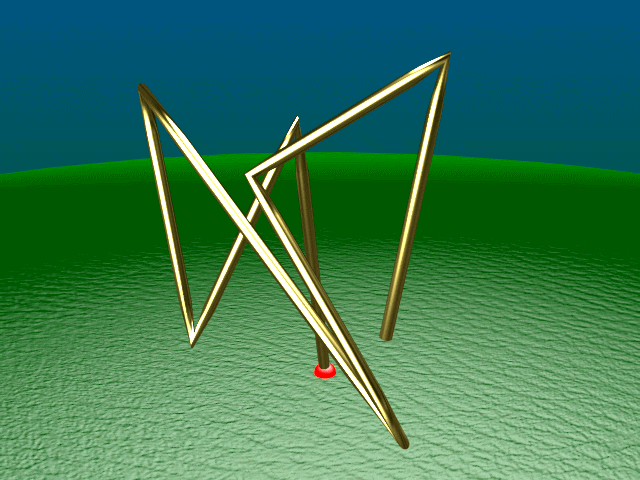
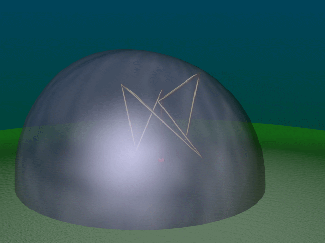
This process has been used successfully to develop antennas where conventional design methods have not succeeded. The resulting antennas are often non-intuitive, but perform well. The application of this method is discussed in [8] to the development of an impedance-feed modulated log-periodic antenna array mounted on the trailing edge of an aircraft wing. Further insight into this emerging strategy can be obtained from [9], which discusses the evolution of an antenna to radiate a circularly polarized field in all directions 10° or more above the horizon at a frequency of 1 600 MHz, and lie within a cube one-half wavelength per side. Figure 31 shows the final antenna shape, and Figure 32 shows the antenna gain pattern.
While the genetic optimising process may be simple in concept, implementation for the development of an improved Black Hawk antenna is not without its challenges:
- The fitness criterion is not self-evident. What constitutes a good NVIS performance? It has already been suggested that maximising the total gain within the upper cone of (say) 30° from the vertical would be a good start. This has to be satisfied over a range of frequencies and altitudes, and it may not be possible to do this with a single antenna configuration. Another criterion that is probably just as important is how consistent the performance can be made with frequency. Less variation should result from reducing the downwards radiation. Whether any significant improvement can be obtained within the antenna space available on a helicopter remains to be seen.
- For the current Black Hawk model, a run at a single frequency and altitude averages 42 min. With populations of some hundreds, and the need to cover about 5 MHz to 15 MHz (needing at least 10 frequencies), and altitude steps of less than one-quarter wavelength from 20 to 400 ft (about 600 runs), the time needed to model a single population of 200 would be close to ten years. By the time a couple populations have been assessed the Black Hawks would no longer be in service!! Clearly some way of reducing the computation time is desirable. This could be achieved in several ways:
- Reducing the complexity of the fuselage model to the point that it just represents the Black Hawk. From previous experience and knowledge of the current model, if it was reduced to only cover 5 to 15 MHz, processing time could possibly be reduced to 20 minutes per run.
- Run the model once in free-space, and compute ground reflection effects externally. This would reduce the number of runs needed per model to 10 (the number of frequencies), adding a small amount of post-processing time. It is expected that this method may introduce some errors at low altitudes (for example under one wavelength). Validation of this method against the original Sommerfeld ground-modelling strategy would be necessary.
- Implementing the above on the present computer would reduce processing of a single population of 200 to just on 1 month.
- Implement parallel computing, for instance, with a Beowulf cluster. This technique uses a large number of computers (possibly retired, and therefore low-cost) controlled by a central computer. Apart from the inhibitions imposed by IT security, this could also be implemented on office computers outside working hours—an otherwise untapped resource. Faster computers would also be welcome!!! Because of the parallel nature of the genetic strategy, it is eminently suited to parallel processing. For a large cluster processing time will approximately decrease inversely with the number of computers in the cluster. Assuming an implementation of all the above methods on a cluster of 100 computers, it is expected that a single population of 200 could be modelled and post-processed in about 10 hours, allowing the hundred or so evolutions that may be required to be processed in a realistic time.
There may also be some benefit in ranking fitness as a function of frequency. This could lead to the evolution of an antenna system that is reconfigured for different frequencies. A number of helicopter antennas in service overseas use this approach and it has the potential to achieve better overall performance with minimal increase in complexity.
Conclusions
Modelling has provided significant insight into the complexity of HF communications from an airborne platform. Validation against measurements to date has been disappointing, and additional work is indicated. Data from the proposed trials will be an essential component of this.
There is a need to develop tools to assist in mission planning, providing information to operators as to the best altitudes and headings for a given communications scenario, as well as providing more intelligent frequency allocation.
Use of more appropriate ground antennas will improve NVIS communications availability, increasing signal strength as well as reducing received noise, both of which are essential in marginal conditions.
It should be noted that this work has not addressed two rotor-related effects—rotor modulation and coning. Rotor modulation arises from the turning of the rotor, and coning from the flexing of the rotor blades during flight. While the impact of these effects on the shape of the radiation pattern need to be considered, they will only be significant when there are significant rotor currents—that is around 9 MHz to 11 MHz. Some discussion of rotor modulation effects is given in [10].
References
[1] ITU-R P Series 617-1, “Propagation Prediction Techniques and Data Required for Trans-Horizon Radio Relay Systems”, International Telecommunication Union Recommendations, Geneva 1992.
[2] N. Balan, et al, “Equatorial Plasma Fountain and its Effects Over Three Locations: Evidence for an Additional Layer, The F3 Layer”, Journal of Geophysical Research, 101, 2047-2056, 1997.
[3] ITU-R P Series 1240, “ITU Methods of Basic MUF, Operational MUF and Ray-Path Prediction”, International Telecommunication Union Recommendations, Geneva, 1997.
[4] A. Nott, “AutoNEC—A Marriage of Convenience”, 10th Annual Review of Progress in Computational Electromagnetics (ACES), Monterey, CA, March 1994.
[5] C. Trueman and S. Kubina, “Verifying Wire-Grid Model Integrity with Program “CHECK”, Applied Computational Electromagnetics Journal, Vol. 5, No. 2, Winter 1990.
[6] S. Kubina, C. Trueman and D. Gaudine, “Modeling the Characteristics of a CH-149 Helicopter Hybrid HF Antenna”, 17th Annual Review of Progress in Computational Electromagnetics (ACES), Monterey, CA, March 2001.
[7] A. Nott, “A Data Compression Technique for Antenna Pattern Storage and Retrieval”, Proceedings of the 13th Annual Review of Progress in Computational Electromagnetics, Monterey, CA, March 1997.
[8] S. Fisher, D. Weile, E. Michielssen and W. Woody, “Pareto Genetic Algorithm Based Optimization of Log-Periodic Monopole Arrays Mounted on Realistic Platforms”, 15th Annual Review of Progress in Computational Electromagnetics (ACES), Monterey, CA, March 1999.
[9] E. Altshuler, et al, “Process for the Design of Antennas Using Genetic Algorithms”, US Patent 5,719,794, 17 February 1998.
[10] T. Firestone, D. Reuster and M. McKaughan “The Effects of Rotor Modulation on a Sikorsky HH-60J Helicopter HF Communication Antenna”, 17th Annual Review of Progress in Applied Computational Electromagnetics (ACES), Monterey, CA, 19-23 March 2001.