
Volume 6, Number 2, July 2003
A Method for Predicting Natural Fragmentation of Warheads
- 1 Ballistics and CFD Group, Cranfield University, The Royal Military College of Science, Shrivenham, Swindon, SN6 8LA, United Kingdom.
Abstract
The purpose of this study is to develop a new method to estimate the natural fragmentation of axis symmetrical warheads. The method is able to predict the projection of fragments at various projection angles, including the fragmentation velocities, types and sizes. It is fairly close to Mott’s fragmentation predictions for cylinders, and to trial data for 105-mm and 81-mm shells. The model captures essential characteristics of natural fragmentation.
Introduction
The purpose of a fragmentation warhead is to generate multiple fragments with adequate mass and velocity to damage the target(s) within its intended lethal zone. There are several ways by which the fragmentation of the casing can be achieved including: natural fragmentation, shear control, metallurgical fragmentation control, inserts, pre-formed fragments, and mass focusing. Fragmentation control is used because the fragment mass distribution is very difficult to assess for natural-fragmentation warheads. However, natural fragmentation is still used in some military applications because it is cheap and provides high strength during firing. There is also a need to assess safety of existing warheads. Although numerical modelling using hydrocodes like AUTODYN or DYNA are currently available for prediction of natural fragmentation, these can be time-consuming to learn and to model the warhead. Moreover, the reliability of prediction is sensitive to input parameters, which are not readily (if at all) available.
This study attempts to develop a new semi-empirical method of predicting natural fragmentation of axis-symmetrical warheads. This will aid in the assessment of the overall lethality of a natural-fragmentation warhead.
Fragmentation process
The fragment size and types obtained (during the fragmentation process) are dependent on case grain size, brittleness, toughness, case thickness, confinement, and explosive fill. The physical processes involved in fragmentation are as follows:
- The detonation of a warhead generates an explosive pressure of around 4×10⁶ pound per square inch that is imparted to the metal case in several microseconds.
- The detonation wave continues along the inner surface of the warhead and exerts pressure on successive cross-sections.
- The cross-sections expand at very high strain rates in a short period of time, resulting in plastic expansion (up to 50% for steel cylinders) and in reduction of wall thickness (probably with strain hardening), until a critical stress for failure is reached.
- The warhead shell fractures into fragments by a combination of shear and brittle fractures.
- After initial fragmentation, the fragments are accelerated continuously by expanding gases, until the gases can escape freely between the fragments. In the meantime, the fragments continue to break up (that is, secondary fragmentation), probably caused by tensile fractures from the interaction of release waves propagating from positions of initial fractures, and by shock-induced vibration.
Fragmentation model
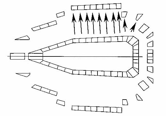
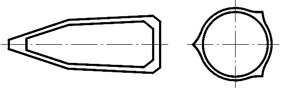
In the proposed method, to model the fragmentation process, the warhead is first divided into small elements, as shown in Figure 1. For the calculation of fragment velocity of each element, we used a methodology proposed in [1], as it appears to be fast and well-suited for differing-in-thickness and general-in-shape warheads. This calculation involves the transformation of the geometry of the warhead into the hollow sphere as shown in Figure 2, assuming constant charge mass and casing mass as well as constant surface area of the charge. Then the Gurney energy balance technique is applied [2-4]. For details on the procedure of the velocity calculation and its validation refer to [1].
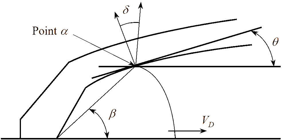
The fragment projection angle is then calculated based on the Taylor angle equation [5], linking detonation velocity, angle of the casing wall relative to the shell axis and fragment initial velocity, as shown in Figure 3. The fragment projection angle was:
(1)
where:
βα = angle of line from origin to point α, to horizontal;
θα = angle of casing to horizontal;
VD = velocity of detonation; and
Vα = velocity at point α.
Correction terms for this equation were cited in [1] but were not used because; in our experience, the magnitude of the correction was too high.
For the distribution of fragment mass, the best known is the Mott equation [6]. A history of developments and several other methods based on the statistical distribution are briefly reviewed in [7]. These methods, however, do not use information related to the varying magnitude and angle of the initial velocity of fragments in the warhead. In contrast, the proposed method relies strongly on these already estimated quantities. The method consists of two major steps: 1) grouping of fragments according to initial velocity and fragment projection angle; and 2) analysis of fragmentation within each group.
With the fragment velocity and fragment projection angle known, the initial warhead elements used for calculation of velocity are grouped according to both similar velocity and projection angle as shown in Figure 1.
It is proposed that the warhead casing will tend to first cleave at locations where there is considerable difference in fragment velocity or projection angle. Elements with similar velocities and projection angles will likely stay intact as a continuous section of the casing, and separate from another element or a group of elements going at different velocity or projection angle.
1) grouping of fragments
For this program, elements are merged together if they have both the velocities and projection angles within 95% of the first element in the group. (It is commonly accepted statistically that values are considered similar when they are within 95%.) These groups of elements will subsequently expand and develop cracks before breaking into fragments.
2) analysis of fragmentation within a merged group
Next, two distances between cracks are calculated for each group. One of the distances is on the internal shell wall, in the direction of the axis of symmetry, while the other is also on the internal shell wall but at right angles to the first. For the cylindrical portion of the warhead, the second distance will be calculated in the circumferential direction, about the axis of symmetry. The equation [8] used is as follows:
(2)
where:
ai = average distance between internal cracks (in);
G = energy per unit area to form a crack (ft-lb/in2);
ri = warhead case radius (in);
ρM = density of case material (slugs per cubic in);
Vo = initial fragment velocity (ft/s).
The present study is limited to the average distance between cracks. It would be desirable to explore effects of introducing an additional randomly distributed factor to Equation (2).
It is proposed that the merged elements will be stressed in two principal directions as shown in Figure 4. As the rate of strain is different in each direction, the distance between cracks in each direction will be different. This is reflected in different radii used in Equation (2). The distances can then be used to calculate the area of the rectangular ‘breakage’ on the internal surface area of the group. The number of ‘breakages’ can then be estimated by dividing the internal surface area by this area.
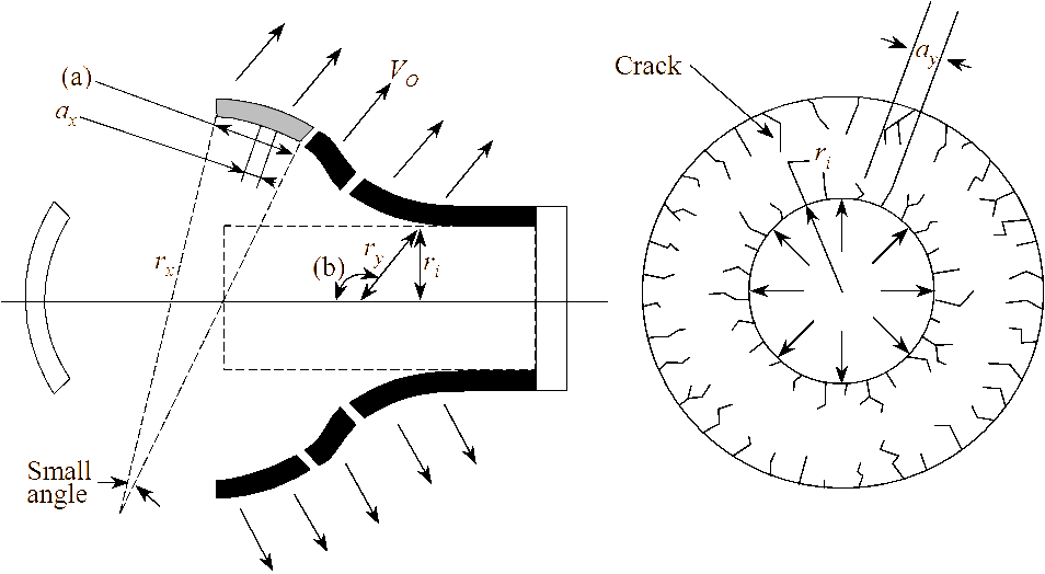
As the elements in the same group are moving in the similar direction and velocity, the distance (in the direction of the axis of symmetry) along the internal surface of the shell for this group, can be taken as the arc of an expanding circle; labelled as (a) in Figure 4. Hence, the radius, rx, can be approximated by the division of this distance of the arc by a small angle. In this case, 0.01 radians (0.57 degrees) was used. The radius, ry, is taken in the direction of expansion, and therefore is computed as the radius at that point divided by the sine of angle labelled as (b) in Figure 4. In cases where the projection angle does not intersect the axis of symmetry, the radius, ry, is also approximated in the same manner as radius, rx.
The type of fragments that are derived from the ‘breakages’ will depend on the ratio between the case thickness of the element and the distances between cracks. If the ratio is small, it is likely to cause shear fractures rather than brittle fractures. If the ratio is large, it is likely to be a combination of both shear and brittle fractures.
For various ratio of thickness to distance between cracks in the direction of axis of symmetry, the following schemes will be applied to estimate the type and size of fragment for the element, as shown in Figures 5 to 8. These schemes are identified by following the classification of fragments proposed by Mock et al [9]. The classification for a thin-walled cylinder of moderate thickness was generalized and the schemes were identified for shapes with double curvature, as it is in warheads. In all the cases, the width of the fragment is the distance between cracks ay.
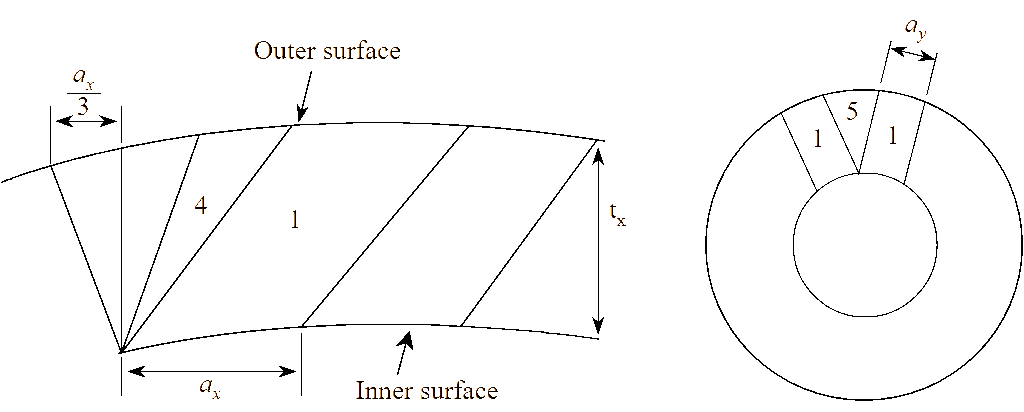
Scheme i: ratio 1figure 4.illustration of crack formation in grouped elements of warhead casing.figure 5.illustration of type and size of fragment for the ratio of tx to ax 1.figure 4.illustration of crack formation in grouped elements of warhead casing.figure 5.illustration of type and size of fragment for the ratio of tx to ax 1.
The basic mechanism for fragmentation assumed is shearing. The basic fragment formed is labelled as “1” in Figure 5. The fragment labelled as “4” accounts for cases where there are curves in the casing, that is when either of the inner or outer surfaces is longer than the other. The fragment labelled as “5” accounts for remaining mass between the basic fragments. The number of fragments “1” and “5”are taken to be equal to the number of ‘breakages’ while the number of fragments “4” will have be calculated based on the difference of the outer and inner surfaces.
Scheme ii: 1 < ratio 2
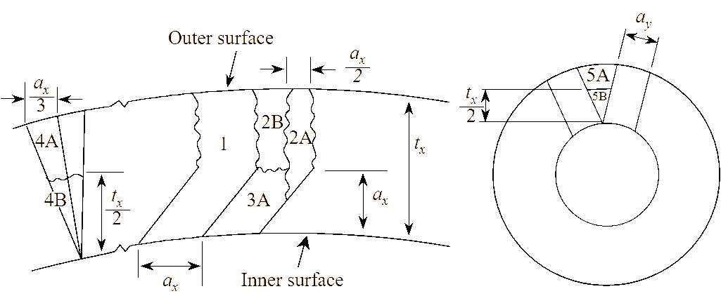
The mechanism for fragmentation assumed is shearing and brittle fracture. The basic fragments are labelled as “1”, “2A”, “2B” and “3A” in Figure 6. The fragments labelled as “4A” and “4B” account for cases where there are curves in the casing, that is when either of the inner or outer surfaces is longer than the other. The fragments labelled as “5A” and “5B” account for remaining mass between the basic fragments. The number of each type of basic fragments is taken to be equal to half the number of ‘breakages’. The number of fragment “5A” or “5B” is taken to be equal to the number of ‘breakages’ while the number of fragment “4A” or “4B” will have be calculated based on the difference of the outer and inner surfaces.
Scheme iii: 2 < ratio 3
The mechanism for fragmentation assumed is shearing and brittle fracture. The basic fragments are labelled as “2A”, “2B”, “3A” and “3B” in Figure 7. The fragments labelled as “4A” and “4B” account for cases where there are curves in the casing, that is when either of the inner or outer surfaces is longer than the other. The fragments labelled as “5A” and “5B” account for remaining mass between the basic fragments. The number of each type of basic fragments is taken to be equal to half the number of ‘breakages’. The number of fragment “5A” or “5B” is taken to be equal to the number of ‘breakages’ while the number of fragment “4A” or “4B” will have be calculated based on the difference of the outer and inner surfaces.
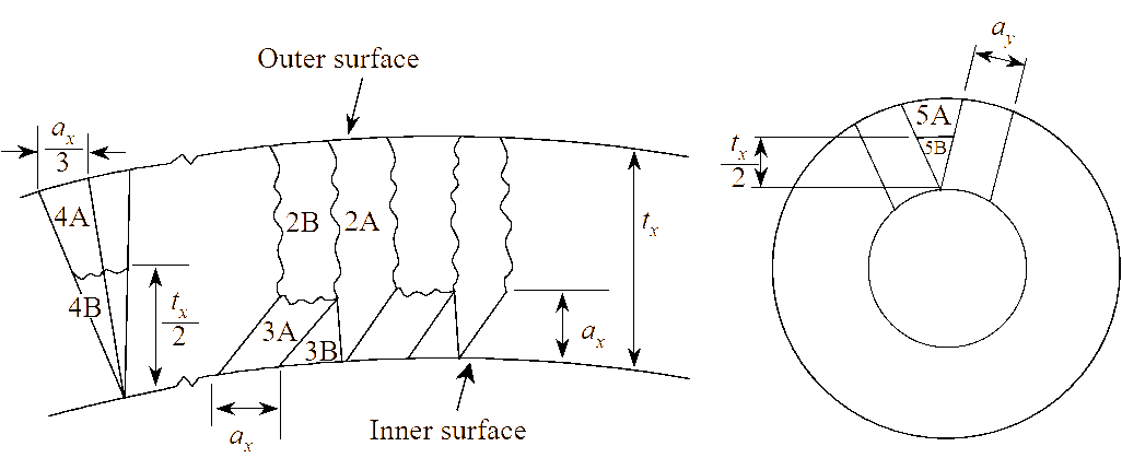
Scheme iv: ratio > 3 figure 6.illustration of type and size of fragment for the ratio of tx to ax 1 but 2.figure 7.illustration of type and size of fragment for the ratio of tx to ax 2 but 3.figure 8.illustration of type and size of fragment for the ratio of tx to ax 3.figure 6.illustration of type and size of fragment for the ratio of tx to ax 1 but 2.figure 7.illustration of type and size of fragment for the ratio of tx to ax 2 but 3.figure 8.illustration of type and size of fragment for the ratio of tx to ax 3.
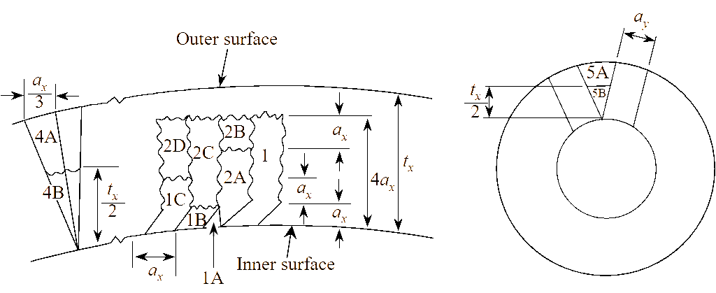
The mechanism for fragmentation assumed is shearing and brittle fracture. The basic fragments are labelled as “1”, “1A”, “1B”, “1C”, “2A”, “2B”, “2C” and “2D” in Figure 8. The fragments labelled as “4A” and “4B” account for cases where there are curves in the casing, that is when either of the inner or outer surfaces is longer than the other. The fragments labelled as “5A” and “5B” account for remaining mass between the basic fragments. The number of each type of basic fragments is taken to be equal to one-fourth the number of ‘breakages’ multiplied by the ratio tx/4ax. The number of fragment “5A” or “5B” is taken to be equal to the number of ‘breakages’ while the number of fragment “4A” or “4B” will have be calculated based on the difference of the outer and inner surfaces.
Results
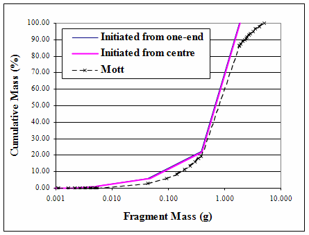
The summary of the final results is presented in a form of graphs of cumulative mass against fragment mass. The fragmentation model is first compared against Mott’s prediction for a simple shape, that is an open-ended cylindrical charge with the length 2.5 times that of the internal diameter (using Comp B as the explosive).
As shown in Figure 9, the curve of the model is not smooth because the current velocity estimation has not taken into account the end-effects associated with an open-ended cylindrical charge. If end-effects had been taken into account, the velocities around the open-ends will be reduced, increasing the range of fragment sizes and giving a smoother curve. Even though the current model has not incorporated this, it is fairly close to Mott’s predictions. In this case, open-end effects are also responsible for a negligible difference when choosing different origins of initiation.
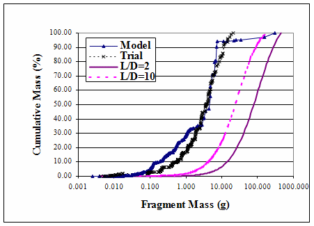
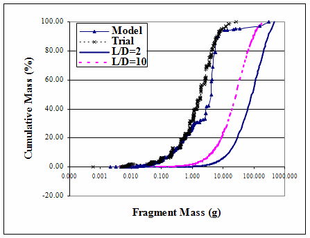
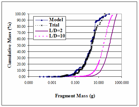
The model was further compared against three sets of unclassified trial data in [10] for 105-mm (TNT), 105-mm (CompB) and 81-mm (CompB) shells, as shown in Figures 10 to 12. The fragmentation estimation by the model is surprisingly close to the actual trial data. The historical approach (by transforming the warhead into a cylinder and then applying Mott’s approximation) is not even close to that of the trial data, even when the length to internal diameter ratio was increased from two to ten.
Compared to Mott’s fragment distribution (and most other fragment distributions), the model has the advantage that it does not use constants that are correlated to actual trial data. It simply relies on estimated velocity and projection angle calculations, the mechanical properties of the warhead shell (that is energy per unit area to form a crack) and with clever generalization of documented fragment characterization, to estimate the fragment mass and size.
Conclusions
A methodology for predicting natural fragmentation has been developed. The initial validation of the methodology shows promise for prediction of natural fragmenting axis-symmetric warheads, obtaining a good estimation of natural fragmentation. Further validation of the model is planned against experimental data, predictions obtained by hydrocodes (Autodyne or Dyne 3D) and other fragmentation equations.
References
[1] D. Jayaratnam, “The Design of High-Explosive Fragmentation”, PhD Thesis, Cranfield University, Royal Military College of Science, UK, 1999.
[2] R. Gurney, “The Initial Velocities of Fragments from Bombs, Shells and Grenades”, BRL Report No 405, Aberdeen Meryland, ATI 36218,1943.
[3] E. Hirsch, “Improved Gurney Formulas for Exploding Cylinders and Spheres using ‘Hardcore’ Approximation”, Propellants, Explosives, Pyrotechnics, Vol. 11, pp. 81-84, 1986.
[4] W. Flis, “Gurney Formulas for Explosive Charges Surrounding Rigid Cores”, 16th International Symposium on Ballistics, 1996.
[5] P. Chou, J. Carleone, E. Hirsch, W. Flis and R. Ciccarelli, “Improved Formulas for Velocity, Acceleration and Projection Angles of Explosively Driven Liners”, 6th International Symposium of Ballistics, 1974.
[6] N. Mott, “Fragmentation of Shell Cases”, Proceedings of the Royal Society, Vol. 189, 1947.
[7] D. Grady and M. Kipp, “Geometric Statistics and Dynamic Fragmentation”, Journal of Applied Physics (American Institute of Physics), Vol. 58, No. 3, pp. 1210-1222, 1 August 1985.
[8] R. Lloyd, “Conventional Warhead Systems Physics and Engineering Design”, American Institute of Aeronautics and Astronautics Inc, 1998.
[9] W. Mock and W. Holt, “Fragmentation Behaviour of Armco Iron and HF-1 Steel Explosive Filled Cylinders”, Journal of Applied Physics, Vol. 54, No. 5, pp. 2344-2351, May 1983.
[10] “Fragmentation Characteristics and Terminal Effect Data for Surface-to-surface Weapons (U)”, Joint Munitions Effectiveness Manual, 61S1-K-UK-3-4, Revision 1, 1 July 1982.