
Volume 6, Number 2, July 2003
Threats to Military Transport Aircraft: A Technical Review
- 1 TDW/EADS, Postfach 1340, 86523 Schrobenhausen, Germany.
Abstract
Without assuming any particular operational scenario, possible threats to military transport aircraft include hits from small arms, high explosive incendiary projectiles with impact or proximity fuzes, frangible armour piercing discarding sabot (APDS) rounds, and small warheads from man-portable anti-aircraft missiles or medium-to-large anti-aircraft warheads. This paper briefly describes each of these threats and their potential effect on aircraft. The hit density as a function of distance is schematically presented whereby high hit densities lead to different synergistic effects. The principal function of radar proximity sensors is briefly described, as well as the prediction of the initial velocities of fragments and their decrease in the ambient atmosphere. Some tests are proposed to define quantitatively the blast/fragmenting loads on aircraft skins with cost-effective individual fragment tests and with fragment generators for high hit densities.
Introduction
While military aircraft structures should be as light as possible, they should also have high resistance to attack by the impact of small-arms projectiles, high-explosive rounds, or anti-aircraft warheads. One of the major difficulties in designing aircraft to survive attacks by these types of threats is that the type of attack will depend on the operational scenario, which cannot (particularly in modern warfare) be accurately predicted in advance. Aircraft therefore need to be protected against attacks from the full wide spectrum of possible threat scenarios.
Threats
The possible threats to military transport aircraft can be divided into three main categories, as illustrated in Figure 1:
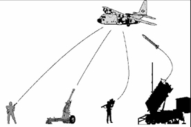
- small-arms projectiles,
- medium-calibre projectiles, and
- blast/fragmenting anti-aircraft warheads fired from man-portable air defence systems (MANPADS) and small missile systems.
Small-arms projectiles (bullets)
Bullets are fired from small arms such as rifles and machine guns. The calibre of the bullets lies typically between 5.56 mm and 14.5 mm. When fired from short ranges, the commonly used ball projectiles can perforate steel that is around 6-mm thick. The so-called hard-core bullets, which have a high-hardened-grade steel core, can perforate approximately 17-mm of rolled-homogeneous armour (RHA) when fired from short ranges.
Sweden [1] has performed tests with 7.62-mm tungsten-alloy projectiles. Figure 2 shows the penetration as a function of distance through RHA of HB 400 and 0° NATO angle compared with a normal AP projectile with a steel core.
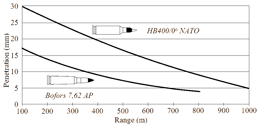
The velocity of a small arms projectile decreases relatively rapidly with distance. Hits against aircraft are therefore only possible when the aircraft flies at low altitudes such as during takeoff and landing or during operation with low-altitude parachute-extraction systems. Consequently, the hit probability of small arms against aircraft is generally very low. However, in a hail of projectiles fired from many rifles, the possibility of some hits on cargo aircraft cannot be fully excluded.
Even if an aircraft is hit by small-arms fire, however, the damage is most likely to be very limited because most impacts will cause only single perforations, or a few perforations widely dispersed. Since military aircraft are generally designed with redundant components and equipment, single bullet strikes are highly unlikely to cause critical damage to the whole aircraft system.
Medium-calibre projectiles
Threats to aircraft come from five different types of medium-calibre projectiles (Figure 3):
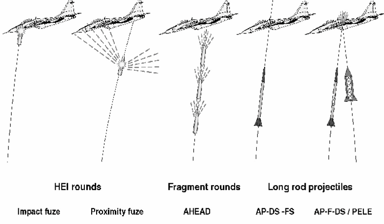
- high-explosive incendiary (HEI) rounds with impact fuze;
- high-explosive rounds with proximity fuze;
- advanced hit efficiency and destruction (AHEAD) fragmentation projectiles with time fuze;
- armour-piercing discarding-sabot fin-stabilized (APDS-FS) projectiles; and
- penetrator with lateral effects (PELE), and armoured-piercing frangible discarding-sabot (AP-F-DS) projectiles.
HEI rounds with 20–30 mm calibres have only impact fuzes. HEI rounds larger than 35-mm calibre can also have proximity fuzes, which detonate the projectile at some pre-determined miss distance from the air target. The largest calibre round with proximity fuzes for use against air targets is the 76-mm HEI projectile, which is mostly fired from cannons on board ships.
Projectiles with jetting fragments (AHEAD munitions) are currently only available for the 35-mm calibre.
APDS-FS rounds are available in the middle-calibre range and were originally designed to defeat medium-hardness targets such as APCs. Modified versions have been specially developed to increase the behind-armour effect after the perforation of lightly armoured skins. These AP-F-DS rounds are also effective as weapons against aeroplanes and helicopters that are also partially armoured. PELE projectiles are a very new concept designed for the same purpose.
HEI rounds with impact fuze
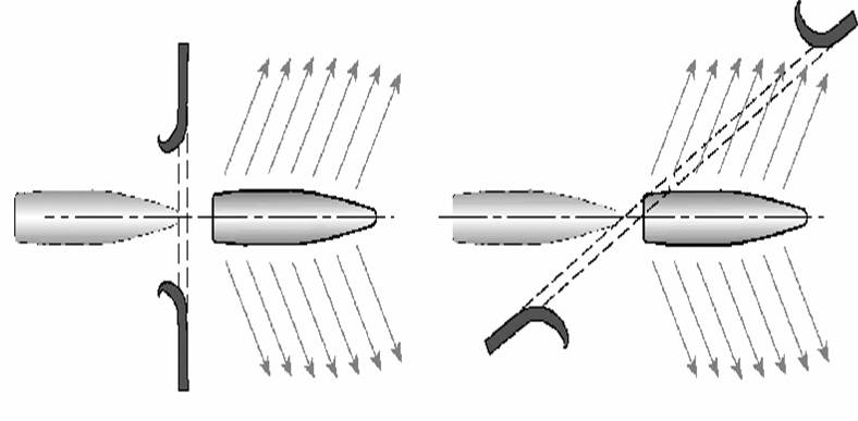
The mechanical impact fuzes react with different speeds depending on the size of the contact area, on the impact angle to the target plates, and on the impact velocities. Typical reaction times as function of the plate thickness for some impact fuzes are given in [2]. The time delay, of for example 100 µs, leads to the fact that the projectile perforates the outside skin and that the fragments hit further internal structures in a cone of roughly 45° in the forward direction (1 000 m/s impact velocity and 1 000 m/s radial fragment velocities in about a 90° direction to the velocity vector). If the target is perforated under 60° NATO angle then roughly only half of the fragment cone is inside the target and the other half is outside (Figure 4). The detonation of the shell and the high-density fragment shower creates a hole in the skin as well as the structure. The size of the hole area depends essentially of the dynamic resistance of the skin and is also a strong function of the obliquity of the impacting HEI rounds.
The probability of kill given a hit PKH by the blast and fragment effect against aircraft can be approximated by the following equation as a function of the high-explosive weight WHE:
(1)
where C has a value of 10 as a first approximation if the high explosive mass WHE is given in kg.
HEI rounds with proximity fuzes
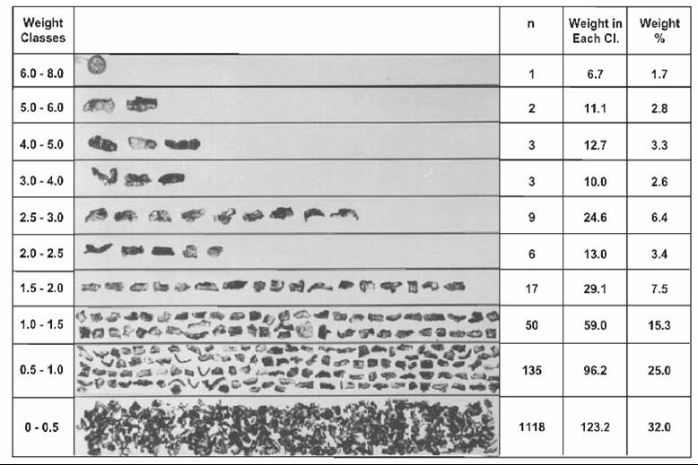
HEI rounds with proximity fuzes not only detonate if they hit the target directly but also if they come within a near-miss distance of the target so that a part of the opening fragment cone will hit the aircraft. The 35-mm OERLIKON projectile 225 MSD/K has approximately 200 effective fragments with masses larger than 0.5g (Figure 5) [3]. The number of effective fragments is not very large and the fragment cone has a large opening angle. The hit density therefore decreases rapidly with increasing distance. The smaller natural fragments with masses below 0.5g are generally not efficient, however, even though their number (in the range of 1 100) is relatively large.
The rate at which the hit density decreases with distance depends on the opening angle ε of the fragment shower—we consider this relationship in the section entitled “Hit Densities”.
In the section entitled “Proximity Fuze Function”, we describe the function of a typical proximity fuze for such rounds, in conjunction with the description of sensors for missile warheads.
Projectiles with time fuze (ahead)
Modern weapon systems can also use new types of projectiles. One example is the ammunition of the Oerlikon Contraves Skyshield 35-mm AHEAD air-defence system (see Figure 3).
35-mm AHEAD rounds are one piece (projectile and cartridge), as are other 35×228-mm Oerlikon ammunition, and are handled and loaded in the same way. The 35×228-mm AHEAD round, Oerlikon designation PMD062, uses a heavy-metal payload projectile with a programmable base fuze. The fuze contains an advanced high precision timer that will detonate an ejection charge according to how it is programmed. The timer is initiated after it has passed through a triple-coil muzzle velocity gauge as the projectile leaves the gun muzzle. The muzzle safety distance for the projectile is more than 60m. As the projectile passes through the first two coils, set 100 mm apart, its exact velocity is determined and processed together with target information supplied by the fire-control system computer. The exact projectile flying time is calculated to thousands of a second and imparted by electro-induction to the programmable base fuze as the projectile passes through a third coil. The high-precision timing module in the fuze then signals the fuze to function and to detonate the less than 1-g ejection charge at a given distance in front of the target, forming a cone of 152 tungsten-alloy sub-projectile pellets, which are directed towards the target. A 25-round burst produces a “swarm” containing 3 800 (152×25) tungsten-alloy pellets covering the expected target position. If the fuze fails to function for any reason, it will self-destruct after 8.19 seconds, an equivalent range of approximately 5 000m. The spin-stabilised sub-projectiles (the spin rate is about 1 000 rps) were designed to be capable of defeating any missile, drone or remotely piloted vehicle by kinetic energy alone, whatever front-end armour they might possess. Each cylindrical tungsten-alloy sub-projectile weighs 3.3g. The complete payload is stacked in eight layers, with each layer containing 19 sub-projectiles.
Long-rod projectiles (APDS-FS and ap-f-ds/pele)
APDS-FS rounds (see Figure 3) are used in medium-calibre cannons, and are designed to be effective against light- or medium-weight armoured vehicles. The rod is typically made of sintered tungsten alloy. The penetration capability achieved against RHA armour plates is approximately three times the cannon calibre. The rods of these KE rounds easily perforate the thin and light armour structures of fixed- or rotary-wing aircraft. Since they deposit energy only on their trajectory, however, the damage is minor unless they hit an essential internal component.
To achieve more damage in a larger area on light target structures, more brittle rod materials are in investigation which spread more radially in a wider fragment cone after the impact. The AP-F-DS and PELE projectiles are recent developments that are designed to mushroom after impact on thin and light plates to achieve larger hole diameters with radially spreading fragments of both the projectile and the target plate. The abstract of the corresponding patent [4] describes this new development as follows:
A projectile for attacking armoured targets, where in a material with substantially no terminal ballistic effect as an expanding medium is radially encased by a penetration material as an outer body with a markedly greater terminal ballistic effect. The expanding medium can comprise light metal, thermosetting or thermoplastic material, fibre-reinforced plastic, elastomer material or a dense and dynamically soft metal. The expanding medium may additionally contain substances with a pyrophoric and/or explosive effect, possibly in the form of powder or liquid. Bars or other bodies can be embedded in the expanding medium. The outer body can comprise high-density sintered metal, a brittle material or high-hardness steel. The outer body can result in the production of fragments. A massive penetrator or a plurality of penetrators can be arranged centrally in the expanding medium. The projectile has a tip and is spin-stabilized or aerodynamically stabilized either as a full-calibre projectile or as a sub-calibre drive sabot projectile. The projectiles may be discharged from dispensers.
These fin-stabilized KE rounds have a relatively high initial velocity of 1 300 m/s with only a small velocity drop along the path travelled by the projectile. They therefore have a relatively high hit accuracy against aircraft in the range of 3 000–4 000m. AP-F-DS and PELE munitions are only recent developments. Whether they are eventually accepted and find a place on the world market remains to be seen, however they are likely to represent a significant threat in the next ten years.
Blast/fragmenting anti-aircraft warheads
There are a relatively large number of different anti-aircraft warheads, which are summarized in Figure 6 [5]. The advantages and disadvantages of these different fragmenting warheads are briefly summarized in Figure 7.
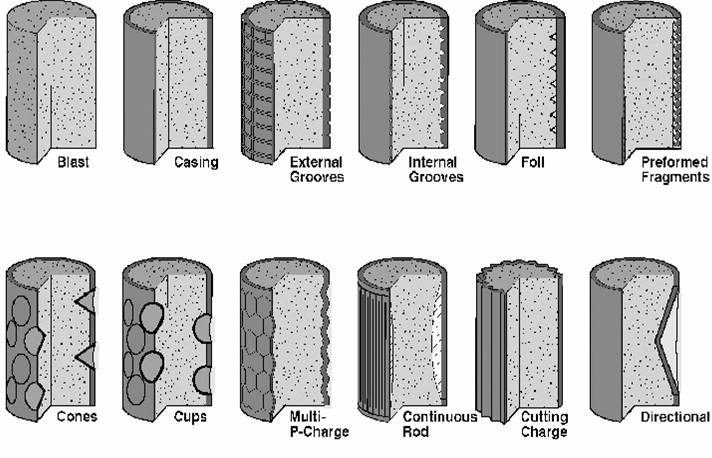
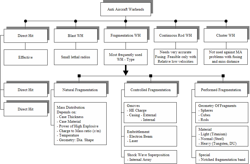
There are practically no blast anti-aircraft warheads because the blast load of a detonating high-explosive charge decreases very rapidly with distance. It is much more useful to transfer a part of the chemical energy of the high-explosive charge into a fragment casing or into controlled or preformed fragments that are able to cause perforations and damage over much larger distances on their discrete trajectories compared to the blast waves.
A smooth casing produces natural fragments as illustrated in Figure 5 for the 35-mm 225 MSB/K OERLIKON HEI round. The effective fragment size is between 0.5g and 2.0g in weight. The sum of these fragments are about 50% of the total casing mass for this round. 30% of the mass gives smaller fragments which are not really effective and about 20% are heavier fragments which represent an “overkill”. To ensure a larger number of effective fragments, a number of controlling mechanisms are implemented. But external grooves are not normally an appropriate way to produce the wanted fragment size, because the fragments do not necessarily break as desired due to by reflected shock wave interactions. Internal grooves, or embedded plastic foils as linear cutting charges in the high explosive charge, or zone embrittlement of the casing can give good controlled fragment sizes if the right casing material and the allowed wall thicknesses for such mechanisms are selected. These methods are less expensive compared to the use of preformed fragments, which require a casing in the structural strength of the warhead and to ensure the rigidity of the missile structure. The advantage of preformed fragments is that the fragment material can be freely selected either lighter, to achieve faster fragments with pyrophoric effects as titanium, or heavy fragments which achieve approximately twice the penetration or perforation capabilities.
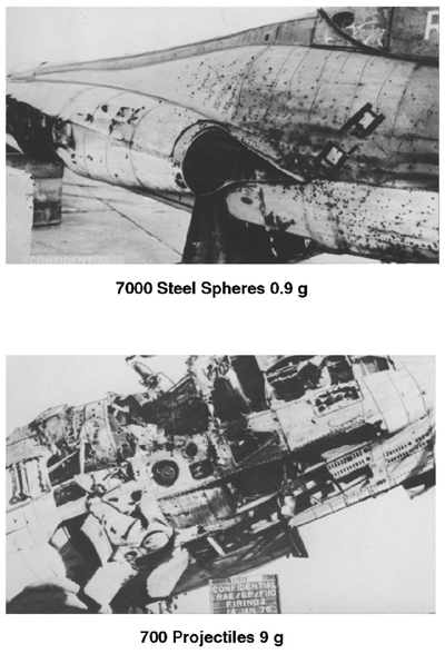
A special warhead is the multi-shape charge warhead which is used in the ROLAND missile. The multi P-charge warhead has twice the perforation capability compared to normal steel fragments in a given warhead diameter. Although the number of fragments is then reduced by a factor of 10, the higher velocities of the large fragments of a multi P-charge have shown much higher structural kill probabilities on skin compared to 0.9-g steel sphere fragments (Figure 8) and additionally an aircraft engine kill because the explosively formed fragments are able to penetrate in the engine whereas the 0.9-g steel balls cannot.
Continuous-rod warheads have been incorporated in a larger number of weapon systems in both the East and the West. The alternative welded rods expand in a meander-shape to a maximum radius through the detonation of the high-explosive charge and should perform a cut in the target. The initial velocity of the rods is only 1 200 m/s. Such warheads need a very accurate fuzing that the expanding ring is able to hit the target in an effective way. This can be not always realized under all possible conditions.
Directional or aimable warheads are concepts investigated in a number of research programs [6].
To defeat incoming tactical ballistic missile warheads (TBM-Warheads) so-called dispersing or cluster warheads are in discussion which are ejecting either a large number of small rods of 30g mass or few rods with, for example, 1-kg masses. Their penetration or perforation capabilities are given by their high relative velocities. But this warhead type, which must be deployed on very expensive missile systems, will not be used to defeat cargo aircraft in the next decades.
Hit densities
Special high-hit density effects
The soft structure of modern composites such as carbon reinforced plastics is not by itself able to resist an individual fragment or to prevent a perforation. As discussed before, however, a single fragment should not appreciably decrease the survivability of the structure. Significant damage is only possible if many fragments with a high hit density perforate the external skin, causing damage resulting from synergistic effects, which can be either additive or cumulative (Figure 9).
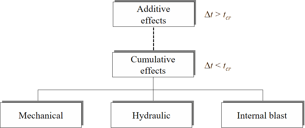
If the hits occur simultaneously (or at least within a very short period) cumulative damage effects arise. This damage can be larger than the sum of individual holes produced over longer periods. The author has defined the expression “additive effects” to describe the effects if the time differences between the individual loads are long [7].
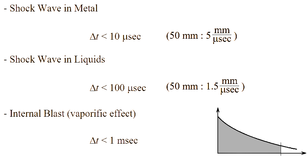
“Cumulative mechanical effects” occur if shock waves from fragment impacts overlap in the structure. This is the case if the time between the fragment impacts in a metal structure is less than 10 µs and the impacts occur within 50 mm of each other (Figure 10). In hydraulic components, hydraulic ram effects are cumulative if impacts occur within 100 µs. Fragment impacts in closed volumes lead to a quasi-static overpressure will arise by the reaction of the fragment and target splinter clouds with the oxygen of the air in the internal volume. These individual internal pressures of every penetrating fragment then overlap, if the time differences of the impacts in the same volume are less than 1 ms.
Composite structures, made from carbon reinforced plastic, have cumulative effects that are different to those of aluminium skins. The damping effect of shock waves are much more pronounced in composite materials than in metal plates and therefore a much lower mechanical cumulative damage effect is expected. Further it has been demonstrated that fragment hits on composite materials will not produce any light flash on the entrance and exit side [8]. This drastically reduces the temperature rise in an internal volume with a composite skin. Therefore the structural damage will also be essentially reduced upon being struck by a fragment shower or by many fragments in a short time interval.
Further, it is possible that hydraulic shock effects with blisters (plastic foils with air bubbles) on the walls of the fuel tanks can be reduced to acceptable values. In summary, all the cumulative damaging effects can be drastically reduced with the use of composite structures compared to metallic skins.
Mechanical damage of aluminium targets happens if the energy per unit area is large. Structural damage on metal skins will be achieved with 1–2 MJ/m. These values are evaluated by tests on aircraft structures and are called McNaughton criteria. For this the number of fragments in the area must be larger than 50. The equation is:
(2)
where the formula represents the product of the kinetic energy of the individual fragments and of the hit number n in the area A, divided by the square root of the loaded area A. This equation of structural kill was evaluated on skins of aluminium. The author does not know of any investigations conducted on composite targets.
Delaminations of composite plates around a fragment perforation are partially observed by a single fragment perforation test. They can be partially reduced by special weavings. Cumulative effects on composite structures have to be proven in detail where such targets are loaded by fragment generators with adjustable hit densities. The hit density can be simply changed by the distance between the fragment generator and the target.
Such a test has been conducted during the investigation of cumulative hydraulic effects on fuel-tank structures made by a composition cover plate [8].
Calculation of hit density
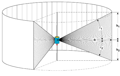
Every warhead has a different hit density that depends on the number of fragments used n, the effective opening angle 2ε of the fragment distribution and on the distance R between the warhead/HEI round to the target.
The hit density ρ() is defined by the number n of the fragments on the warhead, divided by the covered area A. The area A itself is given by the circumference of the circle with the radius R and the heights h1 and h2 of the fragment tube. The heights h1 and h2 can be described with the opening angles of the fragment distribution ε1 and ε2 in the forward and the rearward directions. See Figure 11.
(3)
(4)
where:
and (5)
The equation for the hit density,, is therefore given by:
(6)
With ε1 = ε2 = ε, the hit density is:
(7)
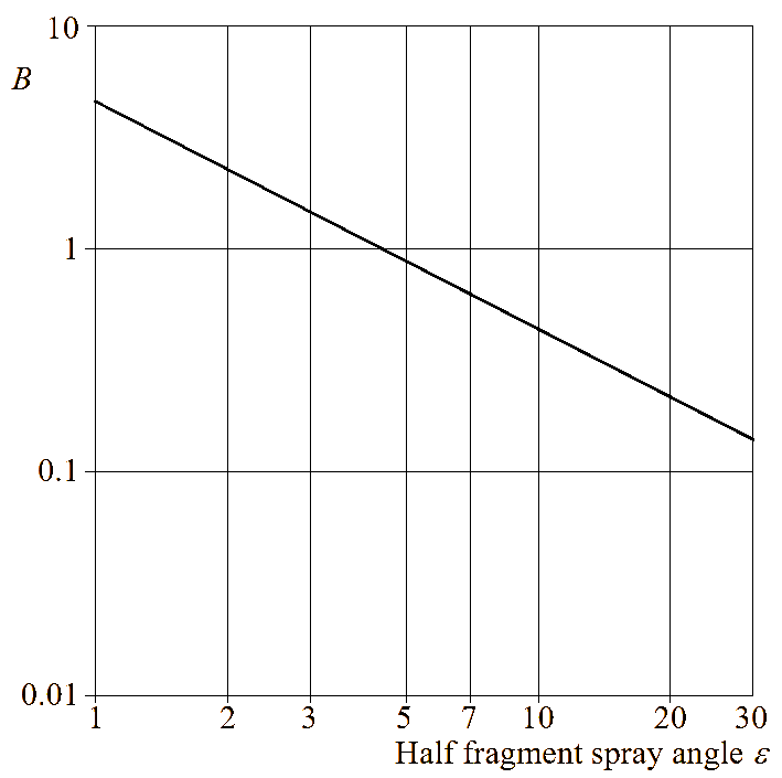
The term ) can be defined as a constant B, which leads to the simple equation:
(8)
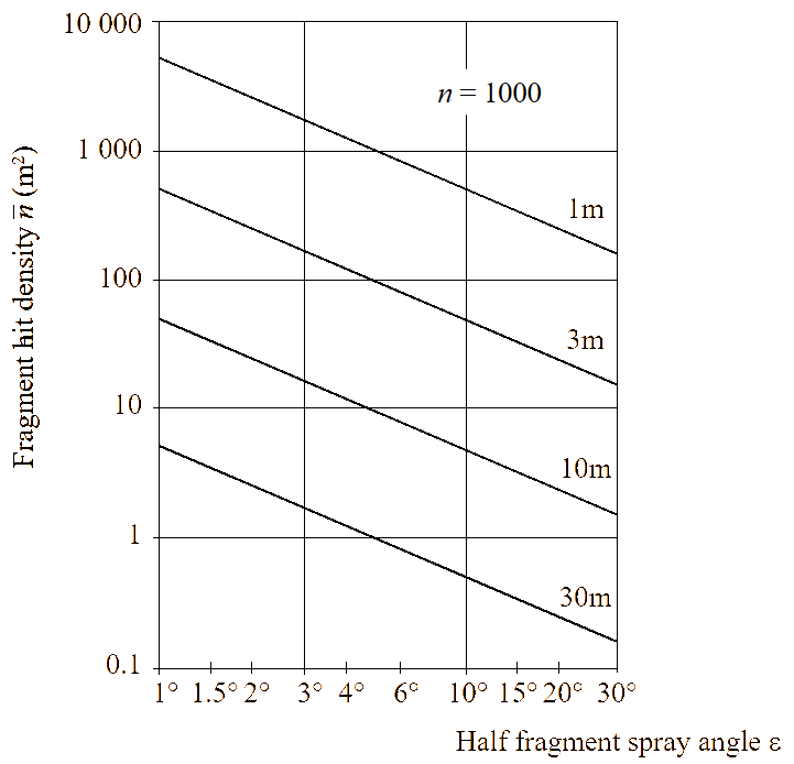
The constant B is a function of the opening angle ε of one side of the fragment beam and can also be taken from the diagram Figure 12. A typical opening angle ε of one side is 9° of a smooth cylindrical fragmenting warhead. This gives the numerical value of 0.5 for the constant B.
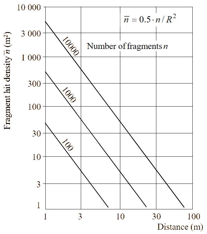
With this very simple equation the hit density can be described as a function of the distance R for a fragmenting warhead with 10 000, 1 000 and 100 fragments (Figure 13).
The strong influence of the opening angle ε on one side of a fragment beam to the hit density ρfor 1 000 fragments on a warhead is illustrated in Figure 14 for ranges R between 1–30m.
The weapon system PATRIOT was originally optimised against military aircrafts. The anti-aircraft warhead has 21 000 steel cubes with 6.5-mm side length respectively 2.1g weight. To defeat tactical ballistic missiles 45-g fragments as platelets of 20×20×14 mm3 size are used.
The vulnerability of a target can be approximated by the following exponential equation, whereby the kill probability P as a function of the individual kill probability pe of one fragment and the number n have to be taken into account with the following equation:
(9)
Some targets or important components are special protected by armour plates. To perforate these, a minimum mass of the fragments is necessary. If targets with softer skins are defeated with such massive fragments the number n of hits is remarkably reduced but the individual kill probability pe is much greater. Therefore, sufficient kill probability can be expected with the large fragments.
The dramatically reduced number of the large fragments is not implying a structural kill with the described cumulative effects.
Proximity fuze function
Target proximity fuzes are necessary to ensure that the fragment cone of a projectile or missile warhead strikes the target, even though the projectile is in trajectory that will miss the aircraft.
In a simple proximity fuze the opening angle η for the sensor cone is defined by the mean fragment velocity vF and the typical relative velocity vR between the aircraft and the missile (Figure 15). This opening angle η can be simply defined therefore as:
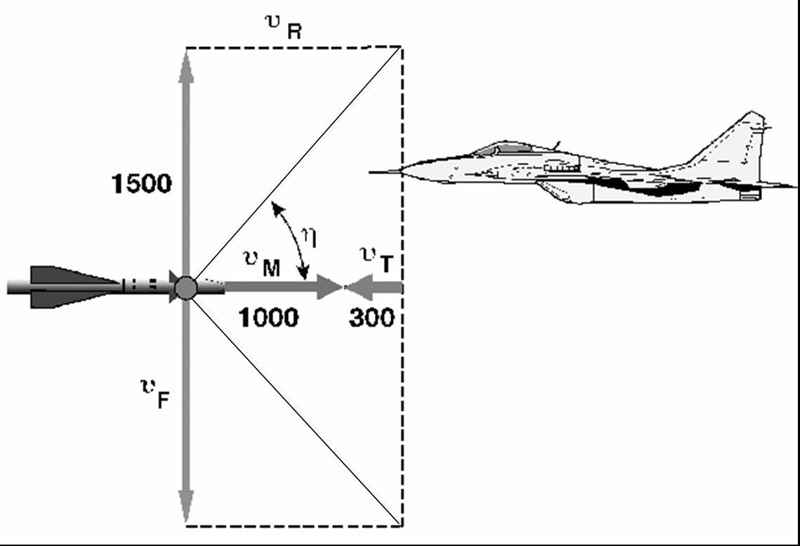
(10)
The relative velocities can be defined from the typical values of 600 m/s for missiles, and 800 to 1 000 m/s for HEI projectiles, and 200 m/s to 300 m/s for the aircraft. Because the velocities of the missile and projectiles are typically changing a larger opening angle of the fragment beam ε is used to cover the total parameter field.
After the trigger signal from the proximity fuze, a time delay Δt is generally added to the firing signal of the warhead. The target should be hit on vulnerable components such as the cockpit which contains the pilot and all the sensitive electronic components on the aircraft.
The angle η can be relatively simply defined by the change of the Doppler frequency of a radar sensor as the target approaches. Instead of using a “constant-look-angle sensor”, which is typically used for optical sensors, modern radar fuze sensors measure the relative velocities and define the firing angle η.
Further, the delay time Δt is not set to be constant, but a constant distance Δs of, for example 3m, is added to ensure that the fragment cone is always in the most vulnerable area of the air target independent of the relative velocities. This constant distance can be also simply derived by counting a constant number of Doppler frequencies.
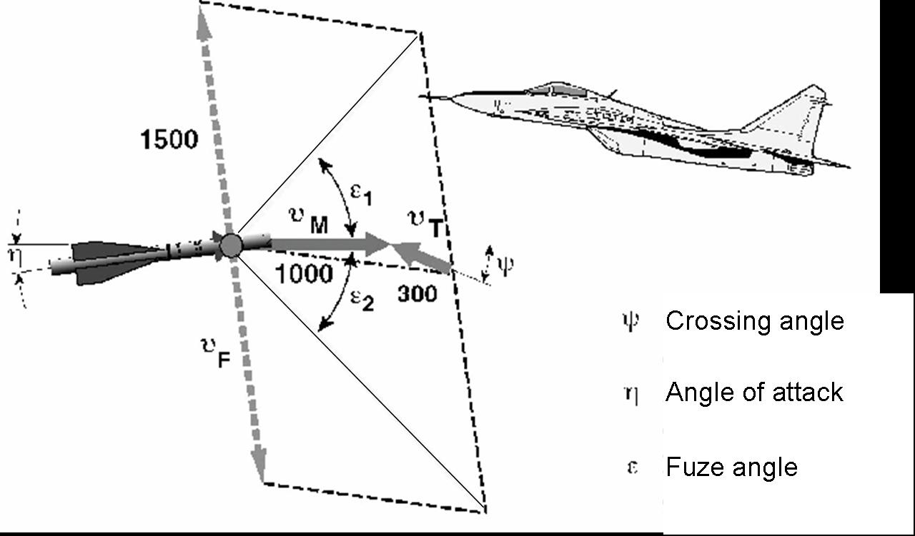
An exact front-on engagement situation between missile or projectile and target rarely occurs so that some angle of attack between the missile axis and the velocity vector must be considered (Figure 16). These deviations from the ideal case are compensated with a larger fragment opening angle ε of the warhead. This is naturally achieved by the shape of the HEI projectiles.
Fragment velocity
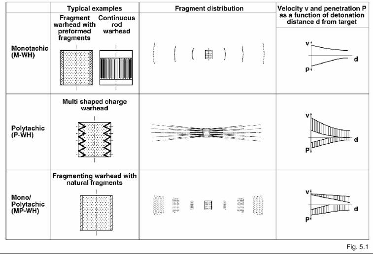
Fragmenting warheads according to their fragment velocity distribution
For lethality studies the possible initial velocities of the fragments are:
- Monotachic warheads, in which the fragment velocities are more-or-less equal and they start with a continuously opening ring. Their velocities decrease with distance due to the air drag forces.
- Polytachic warheads, where the fragments start with different velocities such as those formed by a multi-shaped charge warhead.
- Mono/polytachic warheads, such as natural fragmenting warheads, where small and large fragments are produced. All fragments have the same starting velocity, but the small fragments are retarded more heavily by the air drag compared to the larger fragments which, after some distance, are in front of an opening ring.
Figure 17 schematically presents typical warheads for these three categories (second column); the corresponding fragment distributions (third column); and the typical velocities, and consequent perforations as a function of distance (fourth column).
Initial velocity after gurney
The initial velocity of the mono- and subsequent mono/polytachic warheads can be defined simply using the Gurney equation.
(11)
In this equation v0 means the initial velocity, the so-called Gurney constant which lies typically between 2 000 and 2 600 m/s, m the casing mass in the cylindrical part of the warhead, not including the flanges, and c the corresponding high explosive mass.
Equation (11) gives a good first indication of the fragment velocities. A more precise prediction can be evaluated if more information is known such as the type of high-explosive charge, the length to diameter ratio of the warhead, and the type of fragment casing (smooth casing or controlled fragmentation or preformed fragments).
Equation (11) cannot be used for shaped-charge warheads, because the fragment shower is generated by a collapse process with typical tip velocities of up to 5 000 m/s. Fragments with this high velocity are eroded during their passage through the air so that, over distances of 30–50m, fast fragments with velocities over 3 000 m/s are mostly consumed by erosion.
Fragment velocity reduction in air
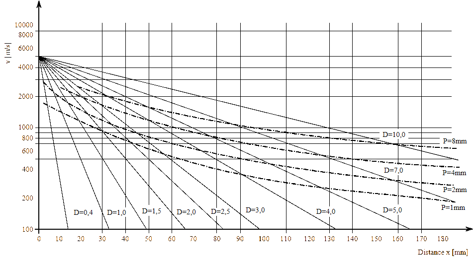
The velocity of fragments decreases in air in accordance with the following equation:
(12)
where v is the actual velocity, v0 the initial velocity, cW the air drag coefficient, which is roughly around 1, ρA the air density which is around 1.28 kg/m3, A the mean cross section of the fragment in the flying direction, x the distance and m the mass of the fragment.
The cross section area A and the mass m of steel spheres can be simply described as a function of the diameter D. For steel spheres with the diameters D, Equation (12) can be expressed as:
(13)
Over a distance of 10m a steel sphere of 10-mm diameter and a weight of 4g, loses 11% of its velocity whereas a 1-mm, 0.004g steel sphere has already lost some 70%.
The mean presented area A of an irregular fragment can be calculated after Cauchy:
(14)
where A is the mean presented area and S the surface area of the fragment body.
Figure 18 shows the decrease of the fragment velocity in a logarithmic linear diagram over the distance with the diameter of the steel spheres as parameter (solid lines). The dotted dashed lines show roughly the necessary velocities for the perforation of aluminium plates with different thicknesses with steel spheres [10]. For example, a 1-mm steel sphere needs a velocity of 1 300 m/s to perforate a 1-mm thick aluminium plate, but a 5-mm steel sphere only requires a velocity of 250 m/s.
Test recommendation
Single fragment tests
To study and compare the delamination behaviour of composite materials, single fragment impacts should be performed. The damage is surprisingly increased with moderate impact velocities or those near the threshold values, because a better impulse transfer mechanism is given over a larger area compared to high impact velocities where the target plate is simply penetrated. To achieve reproducible and comparable results, a sphere (or at least a hemispherical shape) should be used at the front of the fragment.
The simplest method is to study this with steel spheres launched by sabots from a smooth-bore cannon under different velocities. This is a relatively expensive process, however, due to the manpower needed to define the velocities, to catch the sabots before the target impact and to handle the cannon.
Spherical fragments can also be accelerated by a small amount of high explosive. Pre-tests can be used to define the necessary high-explosive weight of a pasty formable composition, which produces reproducible velocities. Single-fragment generators can be prepared which launch the spheres to velocities between 100 m/s and 1 000 m/s in 100-m/s velocity steps. After the calibration tests individual velocity measurements are no longer necessary. The amount of high explosive is small and the tests can be conducted in a steel tube or vessel that allows a large number of tests in short time intervals.
Define the damage at high hit densities
To define the cumulative effects on target plates, fragments must be generated with different high hit densities. Reference [8] describes a fragment generator with 3.5-g cubical steel fragments with velocities around 1 100 m/s in the central region which decrease along the central cross section to 900 m/s and down to 700 m/s on the diagonal edges. The hit density can be simply changed by varying the distance between fragment generator and the target. If desired, such a fragment generator can be designed for other fragment dimensions and different velocity ranges.
The damage by cumulative fragment impacts on composite plates should be measured because it can weaken the total structure and strongly influence the survivability of the aircraft.
Hole area at HEI projectile detonations
The detonation of HEI projectiles creates holes by the blast wave and the fragment shower loads. This hole area and geometry depends on the geometry of the projectile, the velocity and the impact angle of the projectile, the delay time of the impact fuze, type of the high explosive composition and also on the composite plate.
To test the strength or behaviour against such a threat it is recommended to use a standard high-explosive charge in a cylindrical metal casing which is detonating in a static test under a NATO angle of 60° to a plane composite plate (Figure 19).
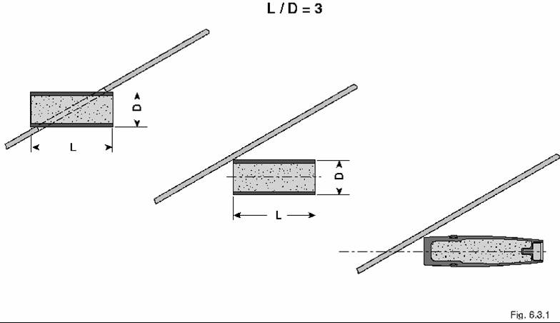
This method does not fully represent the load of a projectile under dynamic conditions. However, HEI projectiles fired from a cannon with impact fuzes do not give reproducible results due to the variability in the fuze response time and requirement for large safety distances on a test range. The standard test proposed above would give much less scatter on load conditions and can be performed with much lower costs.
If HEI projectiles are readily available then such static tests should be performed with, for example, 30-mm HEI projectiles which are also set in contact to the target plate under 60° (Figure 19). An electric detonator can initiate the charge over a booster instead of the use of a proximity fuze. Real HEI projectiles still give a more-realistic fragment distribution in static tests and the expenses can be held low, if the HEI projectiles can be obtained from an inventory (magazine) at no/or low costs.
Summary
There is a widespread future threat to military and civilian aircraft, either by military conflict or terrorist attack. This paper has presented an overview of the range of threats from bullets fired from small arms, from medium-calibre projectiles with different layouts, as HE-rounds, AHEAD ammunition, APDS-FS, or AP-F-DS and PELE projectiles, and from MANPADS or small missile warheads.
Single individual fragments will not create critical damage. Therefore this paper addresses the hit density with the associated synergistic effects. The principal function of radar proximity fuzes is briefly described, along with the prediction of the initial fragment velocities and their deceleration through ambient air. Finally simple advice is given for testing the survivability of aircraft panels by simple or multiple fragment impacts, resulting from detonation of HE rounds with small investment and low cost.
References
[1] http://www.fmv.se/index.asp?K=00501100400&L=UK.
[2] M. Held, H. Giovanelli, and G. Sögtrop, “Procedure for Measuring the Response Time of Mechanical Impact Fuzes for Projectiles”, Propellants, Explosives, Pyrotechnics, Vol. 9, pp. 139-146, 1984.
[3] M. Held, “Fragment Mass Distribution of HE – Projectiles”, Propellants, Explosives, Pyrotechnics, Vol. 15, pp. 254-260, 1990.
[4] G. Kellner and H. Junghans-Strasse, “Projectile or Warhead”, International Patent 197 00 349. 4, Priority date 8 January 1997.
[5] M. Held, “Anti-Air Warheads”, International Defence Review, 719-724, 1975.
[6 M. Held, “Aimable Fragmenting Warheads”, 13th International Symposium on Ballistics, Vol. 2, 539-548, 1992.
[7] M. Held, “Fragmenting Warhead”, in J. Carleone, Tactical Missile Warheads, pp. 447–452, 1993.
[8] M. Held, "Fragment Threat Against Aircraft Structures", Conference on Transport Aircraft Survivability, St. Louis, Missouri, USA, pp. 135–148, 1993.
[9] M. Held, “Fragment Generator”, Propellants, Explosives, Pyrotechnics, Vol. 13, pp. 135-143, 1988.
[10] M. Held, "Splitterballistik" Explosivstoffe, Part 1: 15, pp. 265-274, 1967, Part 2: 16, pp. 49-55 and Part 3: 16, pp. 73-78, 1968. Translations in English are available: "Fragmentation Ballistics", Atomic Weapon Research Establishment (AWRE), Translation No. 64, May 1972; "Ballistics of Projectile Fragments", translated by R. F. Brinkley, Bureau of Mines, Pittsburgh, PA, USA, Oct 1968.
Acknowledgement
The author would like to thank Christian Less very much for the motivation, the detailed discussions and the great support to this paper.