
Volume 6, Number 1, March 2003
Experimental and Computational Research for Conceptual Design of Mine-Resistant Boots
- 1 Air Vehicles Division, Defence Science and Technology Organisation (DSTO), 506 Lorimer St, Fishermans Bend, Melbourne, Victoria, 3207, Australia.
Abstract
Experimental and computational research has been conducted for conceptual design of mine-resistant boots. In the experiment an explosive charge generated a shock impact to a metal wedge supporting a steel surrogate leg. The impact load received by the leg was recorded via strain gauges. The effect of a number of factors such as standoff distance, wedge-angle and energy absorbing materials on the impact load was explored. It was found that the impact load is sensitive to the standoff distance but less sensitive to the change of the wedge angle. Use of honeycomb materials may reduce the impact load significantly. A Dyna3D finite element analysis was also performed. The modelling results were in close agreement with the measured results thus demonstrating the utility of the finite element method as a useful tool in the design and development of mine-resistant boots.
Introduction
Anti-personnel landmines (APLs) are generally used in military operations for area denial of dismounted personnel. Those areas also include anti-vehicle landmine (AVL) fields where APLs are used to protect the AVLs from clearance by deminers. It is estimated that over 100 million APLs are currently deployed throughout the world [1]. These mines pose a severe threat to military and NGO personnel, as well as to the local civilian population.
APLs are classified by their primary injury mechanism as being either of the fragmentation, or the blast type. Blast-type APLs are the most prevalent type worldwide. Their resultant injuries are characterized by traumatic amputation, lacerated, contused and devitalised tissues, disruption of local blood supply, the presence of non-sterile foreign bodies and infectious contamination by various micro-organisms. APL’s general design purpose appears targeted at causing traumatic amputation of the distal portion of the unprotected lower limb, leaving the adversary injured, but alive.
In order to protect people, in particular military personnel, from APL injury, efforts have long been made to develop mine-resistant boots. In the 1950s a model of air-cushioned mine-protective footwear appeared in England. This was followed in the 1960s by a model from the USA, incorporating a honeycomb-filled shank, wedge-shaped heel cut outs and metal heel counters. The latter was tested against US M14 APLs and it was reported that 63% of the protective boots resulted in a foot damage level that could possibly be “salvaged from amputation” [2]. In recent years several new mine-protective boot options have been developed and are now commercially available.
Testing was conducted at the Weapons Systems Division, of the Australian Defence Science and Technology Organisation (WSD, DSTO) to evaluate some of these commercially available mine-resistant boots. Evaluation testing has also been carried out in the USA and Canada [3]. The results from these tests indicated that in order to achieve satisfactory performance, further developmental effort is needed.
Figure 1 gives a section view of a typical mine-resistant boot. The metal wedge is used to protect the sole from rupture and thus diminish the erosive effects of the explosive products. The V-shaped wedge also serves to reflect and deflect the shock wave and thus reduces impact load transmission. The honeycomb material is used to limit impact load and absorb impact energy.
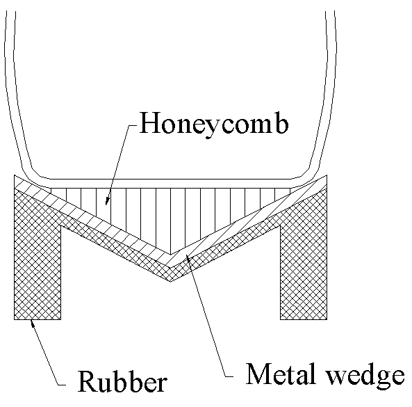
In general terms, mine-resistant boots cannot fully prevent foot and leg injury. The design is targeted at reducing injury level, particularly the prevention of severe injuries that would otherwise lead to amputation. Because APL injury level is directly related to the load transmitted through the boot, the load must therefore be minimised through smart boot design. On the other hand, a quantitative injury criterion related to the load level, however, has not been established in published literature known to the authors. Thus, ultimately, a novel boot design will still need to be evaluated by means of APL tests involving bio-fidelic surrogate legs.
In most available literature regarding the development of mine-resistant boots, novel protective mechanisms were proposed and incorporated in the designs. The prototype boots developed were then evaluated against APL explosions. What has hardly been reported however is fundamental research such as computational and experimental analyses of individual underlaying factors. For the optimal design of mine-resistant boots, such research is essential. WSD’s preliminary research in this area is summarised below.
For the purpose of this study, only the blast-type mine is considered.
Procedure
Experiment
The test set-up is shown in Figure 2. During a typical test, a surrogate mine charge buried in dry sand in a round steel container generated a shock impact to the metal wedge situated above it. The wedge in turn transmitted a vertical load to the steel surrogate leg, either directly, or via shock absorbing material. Strain gauges on the surrogate leg recorded the impact load the leg received.
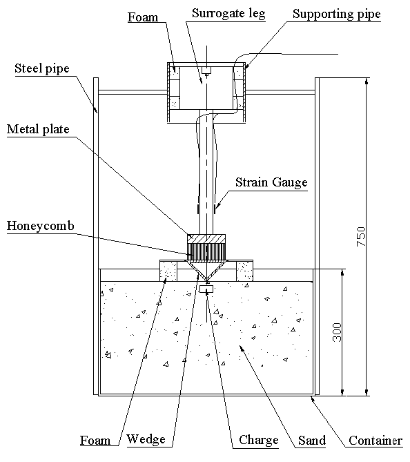
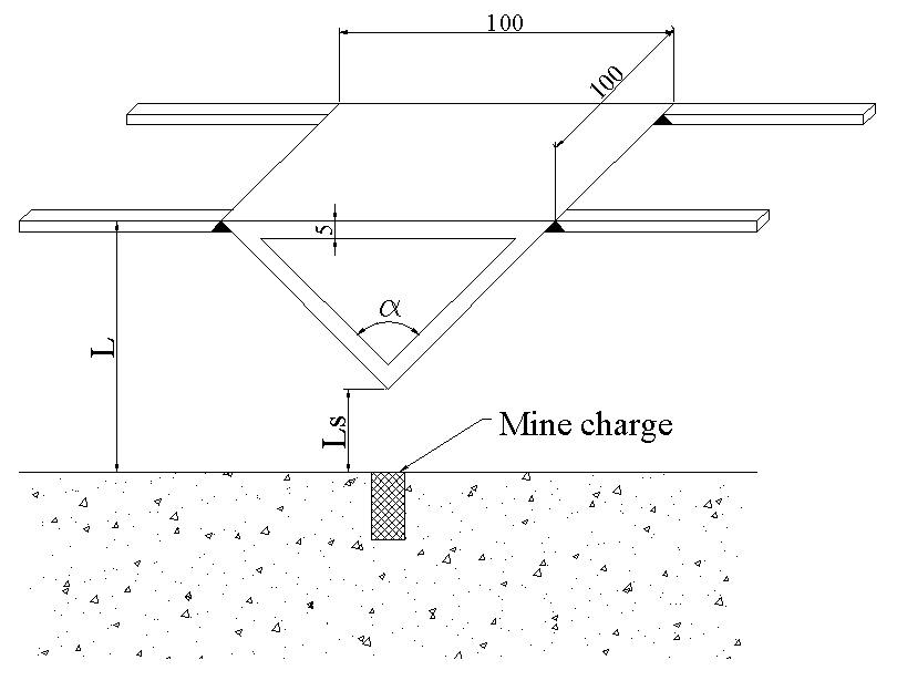
Before detonation, the steel wedge was supported through its four lugs (Figures 2 and 3), on two polystyrene foam blocks. The surrogate leg was horizontally stabilised on its top by means of small polystyrene foam blocks inserted laterally in the supporting pipe connected to the steel container (Figure 2).
The steel surrogate leg developed at DSTO during previous research [4] consisted of a cylindrical mass above a 30-mm diameter rod with a total weight of 11.5 kg.
The following series of tests were conducted:
- baseline tests,
- standoff effect tests,
- wedge angle effect tests, and
- honeycomb effect tests.
In the baseline tests the wedge angle (α) was 90°. The wedge lower tip just touched the soil surface, that is the standoff distance (Ls) was zero. No energy absorbing material was used between the top surface of the wedge and surrogate leg. In other tests, Ls and α were varied, and honeycomb materials were placed between the wedge and the metallic surrogate leg. Three experiments were conducted for each test configuration. In all tests, 10g of cylindrically shaped PE4 explosive of 1-cm diameter was buried flush with the soil surface. A 5-Hz low-pass filter was used for strain gauge signal processing.
Finite element analysis
Figure 4 shows the geometry of the finite element (FE) model. Symmetry considerations dictate that only one quarter of the structure needs modelling. Note that the mesh size is too fine to be shown in Figure 4.
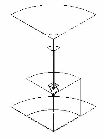
To form the symmetry condition in the FE model, the node transitional displacement normal to the symmetry planes was constrained. The nodes along the interfaces between the explosive, air, soil and steel container were merged. This was the most reliable and economic way to simulate the required contact between these components. The vertical movement along the bottom of the steel container was fixed to simulate the ground restriction.
All meshes were generated using 3D brick elements.
Meshes for the explosive, soil and air were modelled as Eulerian meshes. These three materials were specified as Multi-material.
Note that when the Eulerian mesh is used, for each time step Dyna solves the equations in two steps. In step one it treats the problem as if it was Lagrangian, that is, let the mesh follow the material flow and the mesh deforms. In step two the nodes are moved back to their initial positions (that is, the mesh is fixed) and the solution is mapped from the deformed mesh to the fixed one (advection step). Multi-material option means that up to three different materials can be modelled within the same mesh. The element properties are determined using a weight average technique, in terms of mass flux of the individual materials into the element. Thus, using these techniques in this application, the meshes are fixed in space and the explosive product is able to expand into the meshes initially occupied by either soil or air. In a similar manner, the soil can move into the initial air mesh.
The meshes for the steel container, wedge, honeycomb material, aluminium plate (on top of the honeycomb, Figure 1) and surrogate leg were modelled as Lagrangian meshes. The vertical contacts between these components (excluding the container) were simulated using the DYNA3D contact form ‘AUTOMATIC SURFACE TO SURFACE’ [5] (which calculates normal and tangent forces, and models the interaction between the two parts, along the contact interface). The interaction between the wedge and the Eulerian mesh of air was simulated using Dyna3D coupling form ‘COUPLING LANGRANGE IN SOLID’ [5] (which couples the force and motion between elements of the two components in the FE computation).
Table 1 lists the Dyna material types used for the six materials involved. The material properties and parameters of equations of state (EOS) are also included in the table.
Results and discussion
Effect of standoff distance
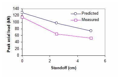
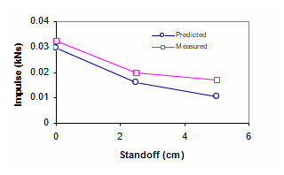
Three different standoff distances, namely zero, 2.5 cm and 5 cm were used. The theoretical and observed peak axial loads and load impulses on the surrogate leg are shown in Figures 5 and 6, respectively. Each of the measured values was an average from three replicate tests. As was expected, the results clearly show that load reduced as the standoff distance increased. Given the possible uncertain factors both in near-field explosion tests and prediction models, the agreement between the prediction and measured results is reasonably good.
- SoilSoilAirAir
| Material | Dyna material types, material property input data and EOS input data (unit = cm, g, µs) | ||||||||
|---|---|---|---|---|---|---|---|---|---|
| C4 [6] | *MAT_HIGH_EXPLOSIVE_BURN | ||||||||
| RO | D | PCJ | |||||||
| 1.601 | 0.8193 | 0.28 | |||||||
| *EOS_JWL | |||||||||
| A | B | R1 | R2 | OMEG | E0 | V0 | |||
| 6.0997 | 1.295E-1 | 4.50 | 1.40 | 0.250 | 9.0E-02 | 1.0 | |||
| Air | *MAT_NULL | ||||||||
| RO | PC | MU | |||||||
| 1.29E-3 | 0.0 | 0.0 | |||||||
| *EOS_LINEAR_POLYNOMIAL | |||||||||
| C0 | C1 | C2 | C3 | C4 | C5 | C6 | E0 | V0 | |
| -1.0E-6 | 0.0 | 0.0 | 0.0 | 0.4 | 0.4 | 0.0 | 2.50E-6 | 1.0 | |
| Steel | *MAT_PLASTIC_KINEMATIC | ||||||||
| RO | E | PR | SIGY | ETAM | BETA | ||||
| 7.9 | 2.1 | 0.29 | 2.75E-3 | 0.021 | 1.00 | ||||
| Al | *MAT_PLASTIC_KINEMATIC | ||||||||
| RO | E | PR | SIGY | ETAM | BETA | ||||
| 2.7 | 0.7 | 0.3 | |||||||
| Soil [7] | *MAT_SOIL_AND_FOAM_FAILURE | ||||||||
| RO | G | BULK | A0 | A1 | A2 | PC | VCR | ||
| 1.8E+0 | 6.385E-4 | 3.0E-1 | 3.4E-13 | 7.033E-7 | 0.30 | -6.9E-8 | 0.0 | ||
| EPS2 | EPS3 | EPS4 | EPS5 | EPS6 | EPS7 | EPS8 | EPS9 | EPS10 | |
| -1.04E-1 | -1.61E-1 | -0.192 | -0.224 | -2.46E-1 | -0.271 | -0.283 | -2.9E-1 | -0.4 | |
| P2 | P3 | P4 | P5 | P6 | P7 | P8 | P9 | P10 | |
| 2.0E-4 | 4.0E-4 | 6.0E-4 | 1.2E-3 | 2.0E-3 | 4.0E-3 | 6.0E-3 | 8.0E-3 | 0.041 | |
| Paper Honeycomb | *MAT_LOW_DENSITY_FOAM | ||||||||
| 1.0E-1 | 2.0E-4 | 0.0 | 0.0 | 0.0 | 0.0 | ||||
| 0.0 | 0.0 | 0.0 | |||||||
| Stress/strain relation | |||||||||
| 0.0 | 2.63E-3 | 5.14E-3 | 8.54E-3 | 1.28E-2 | 1.76E-2 | 0.780 | 0.804 | 0.815 | |
| 0.0 | 1.35E-8 | 2.22E-8 | 3.63E-8 | 5.36E-8 | 6.73E-8 | 6.93E-8 | 7.44E-8 | 8.06E-8 | |
| Stress/strain relation (continued) | |||||||||
| 0.825 | 0.833 | 0.841 | 0.847 | 0.855 | 0.9 | 0.95 | 0.99 | 1.00 | |
| 883E-8 | 966E-8 | 104E-7 | 111E-7 | 118E-7 | 600E-7 | 120E-6 | 400E-5 | 100E-3 |
Effect of wedge angle
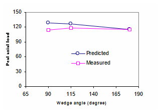
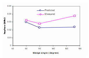
Three different wedge angles, namely 90°, 115° and 180° were used. Note that in the 180° case, the wedge reduced to two 5mm thick flat plates. Note also that in this series of tests, the distance between the top surface of the wedge and soil surface (the dimension L in Figure 3) was fixed at 50 mm, that is, the effect of wedge angle was compared on the basis that the distance between the heel and ground surface was constant. This is necessary since in a boot design this distance generally reaches its upper limit determined by the functional requirement of the boot. A natural consequence on the test configuration is that lower wedge angles are associated with shorter standoff distances.
The measured and predicted peak axial loads and load impulses on the surrogate leg are shown in Figures 7 and 8, respectively. The agreement between the prediction and measured results is also reasonably good. The results show that the load was not particularly sensitive to the variation of the wedge angle. A wedge angle of 115° is probably most preferable in terms of the lower impulse and possibly higher structural strength.
Effect of honeycomb materials
Two different honeycomb materials were used in the tests. One was a 15-mm thick aluminium honeycomb with a crush strength of 1.5 MPa and stroke of 80% strain (that is after initial crush (or pre-crush) during compression the stress of the honeycomb material keeps a nearly constant stress of 1.5 MPa until its strain exceeds 80%). The tests used two layers of pre-crushed honeycomb separated by a thin aluminium sheet. The honeycomb area was 5 cm × 5 cm.
Another honeycomb material used was 40-mm thick Nomex paper honeycomb with a crush strength of about 0.6 MPa and a stroke of 80%. In the tests one layer of this honeycomb material with an area of 9 cm × 9 cm was used.
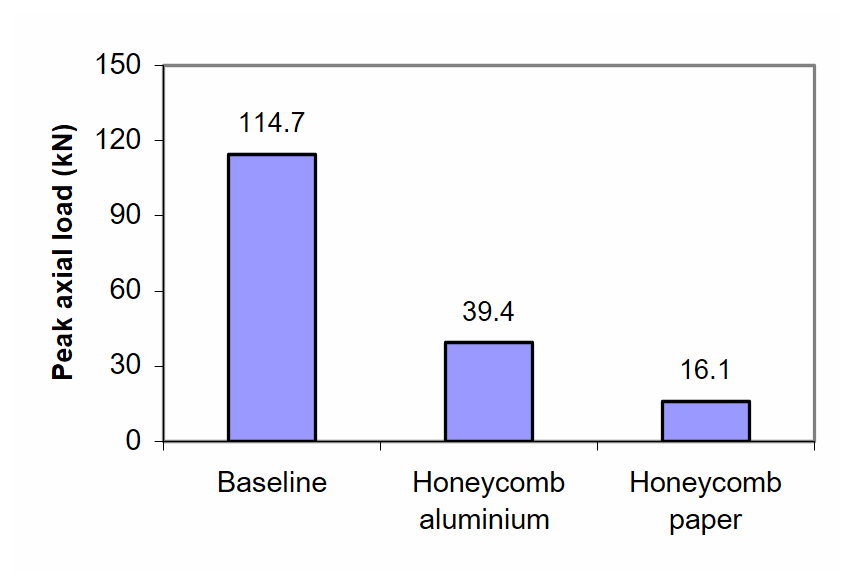
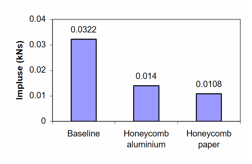
The measured peak axial loads and load impulses on the surrogate leg are shown in Figures 9 and 10 respectively. The results clearly show that the loads were reduced significantly when honeycomb materials were used. The static load limits for these two honeycomb materials may be estimated using their crush strength and areas. These values are 3.75 kN and 4.86 kN for the aluminium and paper honeycombs respectively. One may notice that these are significantly lower than the measured values of 39.4 kN and 16.0 kN shown in Figure 9. The honeycomb specimens were examined after the tests and it was clear that the stroke was not fully completed. Hence, the difference between the static load limit and the measured peak load may be attributed to inertial effects and change of material property under shock load. The paper honeycomb mitigated the impact load more efficiently, probably due to its lower density and stiffness (that is, higher impedance mismatch).
Dyna3D simulation was conducted using the measured static property data listed in Table 1. The maximum load predicted was 12.0 kN at the location of the strain gauges. The difference between this predicted value and the static load limit is clearly due to the inertial effect of the system involved.
Conclusions
- An explosive test device was developed to examine what effect a number of factors such as standoff distance, wedge angle and honeycomb material might have on the resultant impact load imparted to a surrogate leg.
- The impact load was sensitive to standoff distance. It was less sensitive to the wedge angle for a constant distance between heel and ground surfaces.
- In a test with a 10-g PE4 charge and 90º wedge with zero standoff distance, the measured peak impact load on the surrogate leg was 144.0 kN. Honeycomb materials significantly reduced the impact load. In one case where a paper honeycomb material was used, the peak impact load was reduced to 16.1 kN. Paper honeycomb appeared to be more effective than aluminium honeycomb, probably due to a better impedance mismatch.
- A finite element model using Dyna3D software was built to simulate the explosion, shockwave propagation in soil and air, and subsequent interaction with a boot structure. The agreement between the predicted and experimental outcomes was reasonably good. The finite element method is proven to be a useful tool for design and development of mine-resistant boots.
- Further research is to be carried out involving larger charges, more detailed boot designs and investigation of other factors, such as charge offset from the plate centre.
Acknowledgements
The authors would like to thank Mr M. Footner, Mr D. McQueen, Dr I. Lochert, Mr G. Katselis and other colleagues of the authors at DSTO for their help in the testing.
References
[1] Y. Kwon and R. Muschek, “Study of Effectiveness of Countermine Boots”, Recent Advances in Solids and Structures, American Society of Mechanical Engineers, Pressure Vessels and Piping Division (Publication) PVP, Vol. 381, ASME, Fairfield, NJ, USA, pp. 63-70, 1998.
[2] E. Fujinaka and J. MacDonald, Research and Development of Blast Protective Footwear, Fabrication and Proof Testing, Technical Report 67-5-CM. Clothing and Organic Materials Division US Army Natick Laboratories, Natick, Massachusetts. July 1966.
[3] D. Bergeron, G. Coley, M. Rountree, I. Anderson and R. Harris, “Assessment of Foot Protection against Anti-Personnel Landmine Blast Using a Frangible Surrogate Leg”, Proceedings of the 2001 UXO Conference, New Orleans, USA, April 2001.
[4] S. Cimpoeru and R. Woodward, “A Model System for the Analysis of Dynamic Axial Loads on the Lower Leg”, ACAM99, The Second Australasian Congress on Applied Mechanics, IEAust, Canberra, Paper R-043, 10–12 February 1999.
[5] LS-DYNA Version 950, Livermore Software Technology Corporation, Livermore, California, 2000.
[6] T. Hall and J. Holden, Navy Explosives Handbook, Explosion Effects and Properties – Part III. Properties of Explosives and Explosive Compositions, Report NAWC MP 88-116, Naval Surface Warfare Centre, USA, 1988.
[7] D. Kennedy, Materials Property Data, Unpublished report, Orica Australia Pty Ltd, Kurri, NSW, 1999.