
Volume 6, Number 1, March 2003
Numerical Simulations and Experimental Observations of the 5.56-mm L2A2 Bullet Perforating Steel Targets of Two Hardness Values
- 1 Cranfield University, The Royal Military College of Science, Shrivenham, Swindon, SN6 8LA, United Kingdom.
Abstract
A numerical study has been conducted using the explicit non-linear transient dynamic numerical code AUTODYN-2D to analyse the penetration and perforation of EN8 (AISI 1040) steel plate by the 5.56-mm L2A2 Ball round. The steel plate was heat-treated to two different hardness values and quasi-static tensile tests were performed to provide work-hardening constants for the Johnson-Cook constitutive model. A model of the bullet was developed using material data available from existing AUTODYN model libraries and parameters modified based upon the measured hardness of the bullet’s individual components. The numerical results compared favourably with experimental trials where the bullet’s residual momentum after target perforation was measured by means of a calibrated ballistic pendulum. The simulations provided some useful insight into the penetration mechanisms.
Introduction
The 5.56-mm L2A2 ball round consists of a hard steel tip and a lead core encapsulated in a copper-alloy gilding metal. Unlike most ball rounds that have traditionally been used to attack soft targets and contain either a relatively soft steel or lead core, this L2A2 round has demonstrated its ability against a variety of hard targets including steel and concrete.
Due to the bullet’s three-part construction, its penetration mechanisms are relatively complex and vary depending on the nature of the target. To understand how this round penetrates and subsequently perforates a steel target, a model has been developed in the non-linear code AUTODYN-2D. Hydrocodes such as AUTODYN™ can provide useful insight into the penetration event as the user can interrogate a number of material-dependent parameters during the penetration and subsequent perforation. However, there is still limited published data available on the dynamic material properties of the bullet and target materials and, without extensive dynamic testing, a number of approximations have to be made. Therefore some form of calibration with experimental data is needed. Nevertheless, these models can still provide useful insight into the penetration mechanisms.
Experimental programme
EN8 plain carbon steel (AISI 1040) plates were heat-treated to two hardness values of 197 HV and 295 HV. For each hardness value, there were three thicknesses of plate: 3, 6 and 8-mm. After heat treatment, each plate was tested for its hardness and tensile strength. The data from those tests are shown below in Table 1. The values of strength presented here are the engineering values. The true yield strength was used in the numerical model (parameter A in Table 2).
| Plate No. | Hardness (HV) | YS (MPa) | UTS (MPa) |
|---|---|---|---|
| 1 | 197 | 612 | 665 |
| 2 | 295 | 958 | 1 008 |
Each plate was subjected to impact and perforation by a 5.56-mm L2A2 bullet travelling at velocities within the range of 901-932 m/s. The bullets were fired through an Enfield L85 A1 barrel, which was mounted into a proof housing standardised according to NATO STANAG 4164. After perforation, the momentum of the bullet was measured using a calibrated ballistic pendulum.
Numerical programme
The perforation of the steel plate by the 5.56-mm L2A2 bullet was modelled using the explicit non-linear transient dynamic numerical code AUTODYN-2D. This software is explained in detail elsewhere []. However in brief, this code solves the conservations laws of mass, momentum and energy based on initial boundary conditions. The user is prompted for an equation of state that describes the pressure in terms of the internal energy and volume and a constitutive relationship that calculates the flow stress in terms of a number of material and application-dependent parameters including strain, strain-rate and temperature. Failure models can be introduced to describe the failure.
All material models for the bullet were retrieved from the AUTODYN material libraries. The bullet is of a three-part construction with a hard steel tip (618 HV), a relatively soft lead core (10 HV) and a copper-alloy gilding jacket. The hardness of the gilding jacket varied from 24 HV at the base of the projectile to 127 HV at its tip. There is a small gap between the front of the steel tip and the gilding. The nominal mass of the bullet is 4g and it has an average velocity of 920 m/s when fired from a standard proof mount and with a standard cartridges case.
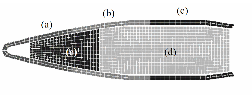
A shock equation of state [Error: Reference source not found] and a Johnson-Cook [] constitutive model was used to simulate the material response to dynamic loading of both the bullet’s tip and the target. The copper gilding metal was modelled using a simple linear equation of state [Error: Reference source not found] and a Johnson-Cook constitutive model; the yield strength of the jacket was varied in three separate sections along the length of the bullet to simulate the variation in hardness. The lead core was modelled using a simple linear equation of state and a Steinberg-Guinan constitutive model []. The failure of the jacket was simulated using a principle strain failure model set at 90%. Figure 1 shows the different parts of the bullet. Parts (a), (b) and (c) represent the gilding jacket with yield strengths of 330, 75 and 30 MPa respectively. Part (d) represents the lead-antimony core (YS = 20 MPa) and part (e) the hardened steel tip (YS = 1 539 MPa).
The EN8 target plates were modelled using a linear shock equation of state and a Johnson-Cook constitutive model. Due to a limited amount of data available on this steel, the parameters for the equation of state and some of the parameters for the Johnson-Cook constitutive model were taken from that available for low-carbon steel (AISI 1006).
The Johnson-Cook constitutive relationship models the effects of the strain, strain-rate and thermal softening on the flow stress of the material and is described by the following equation:
(1)
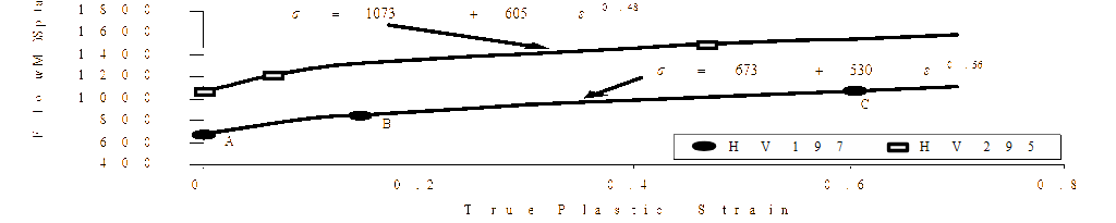
where A is the yield strength of the material, B is the strain hardening constant, n, is the strain-hardening exponent, C is a strain-rate constant, m is the thermal softening exponent and Tm is the melting temperature. The first bracketed term describes a work hardening relationship for the material, the second bracketed term describes the materials strain-rate dependency and the third describes thermal softening. The first bracketed term was established by uni-axial tensile tests for each plate hardness. The true stress at yield, the strain-hardening constant and the strain hardening exponent were evaluated from the true flow-stress strain curve for each of the steels (see Figure 2). The strain-rate sensitivity of the steels (parameter C) was adopted from values used for similar steels in the AUTODYN material libraries. For the third bracketed term, the melting temperature was extracted from the data available for 1006 steel. The parameters for the target plates are shown below in Table 2.
| Plate No. | A (MPa) | B (MPa) | n | C | m | Tm (K) |
|---|---|---|---|---|---|---|
| 1 | 673 | 530 | 0.56 | 0.022 | 1.0 | 1811 |
| 2 | 1073 | 605 | 0.48 | 0.011 | 1.0 | 1811 |
The true fracture strain of the tensile test specimens was calculated from:
(2)
where Ao is the initial area of the tensile test specimen and Af is the area of the fractured surface. This value of fracture strain was used to simulate failure in the target plates using a principal strain failure model [1] and is a conservative estimate. The values of the fracture strains and true stress at failure for each of the specimens is shown below in Table 3.
| Plate No. | Hardness (HV) | True Stress (MPa) | Fracture Strain |
|---|---|---|---|
| 1 | 197 | 1069 | 0.72 |
| 2 | 295 | 1493 | 0.50 |
All simulations used a Lagrangian processor. Therefore, in all of the simulations an instantaneous geometric strain erosion model was used to erode cells that had become severely distorted. The inertia of the eroded cells was retained so that the momentum of the projectile could be calculated after it had perforated the plate. The cell size for the simulations was nominally 0.3-mm square. A user-subroutine was written and implemented within AUTODYN to calculate the residual momentum of the bullet that had perforated the plate. Sensitivity calculations were carried out on the mesh density and material properties of the target and bullet.
Results
Experimental observations
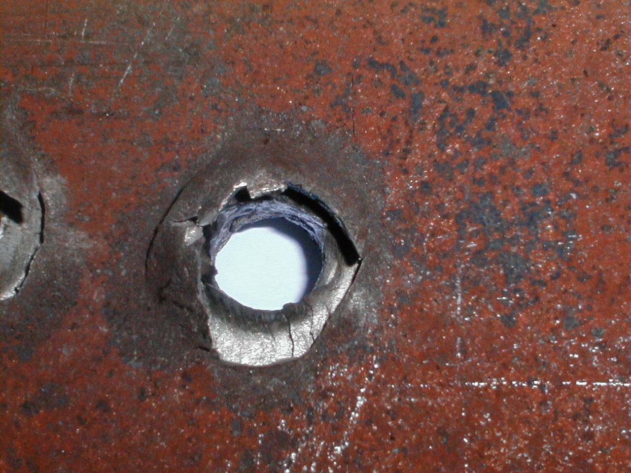
During penetration and subsequent perforation, the gilding metal of the bullet is stripped and deposited in the holes of the plate. For thicker and harder plates, lead was also deposited. For all of the steel targets, failure predominately occurred by ductile flow leading to bulging and ultimately petalling; there was some evidence of spalling with the 8-mm hard plate (Figure 3). No firing was done with the 10-mm 295 HV plate however, from the trend of the experimental results presented in Figure 4, it is expected that the bullet would be stopped by 9.3-mm of hard plate. The bullet was stopped by the 10-mm 197 HV plate.
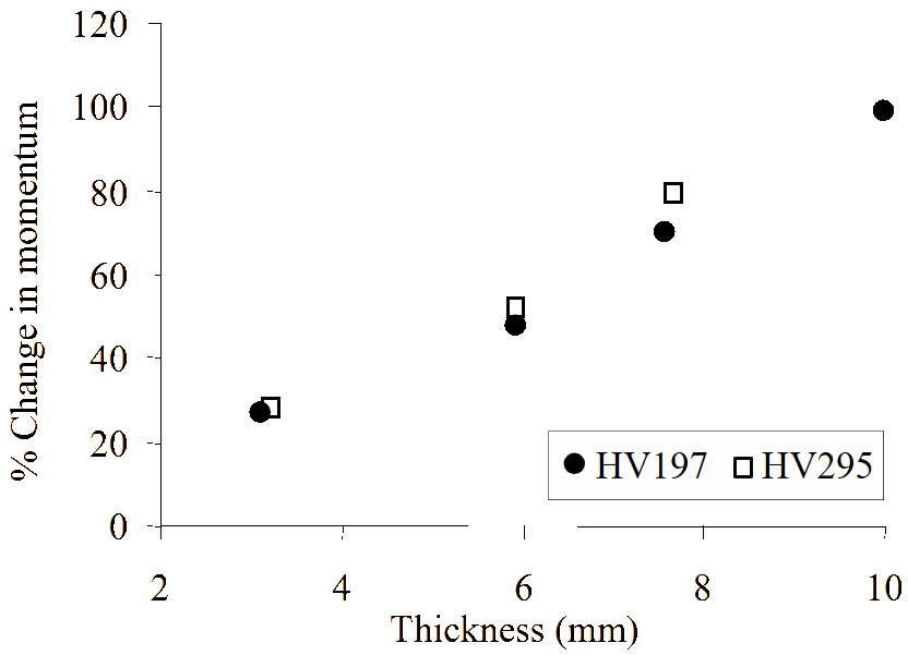
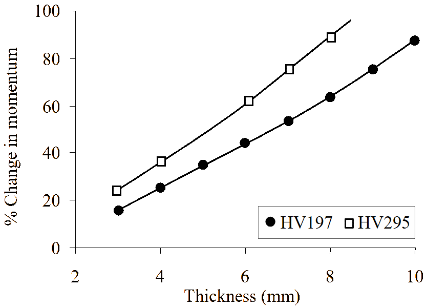
The measured change in momentum of the projectile after perforating each plate is shown below in Figure 4. The residual momentum of the bullet is largely affected by the hardness of the plates for thick plates but is not affected so much when the perforation occurs with thin plates. For example, the measured change in momentum for the 3.2-mm steel plates for all three hardness’s only varied between 26.9% and 28.7%. For thicker plates (7.8-mm), the lower hardness plate incurred a change in momentum of 66.6% whereas the higher hardness plate incurred an average momentum reduction in the projectile of 79.8%.
10mm10mm
Numerical simulations
Overall, the trend of the measured momentum loss of the round with increasing thickness of plate compared favourably with the experimental data. Moreover the measured hole diameters were similar. However the simulations of the round into the harder target overestimated the projectile’s loss in momentum whilst with the softer target, the model underestimated the momentum loss (the maximum difference was 7.8%, which occurred with the 8-mm target plates). The modelling work demonstrated the increased effect of hardness with thicker plates as reported in the experimental phase.
The difference between the experimental and numerical results is largely due to some of the uncertainties that exist with the numerical model. For example, due to the limited amount of dynamic material data for EN8, the strain-rate sensitivity of this material is unknown. Sensitivity simulations have shown that changing the parameter C (strain-rate sensitivity constant in the Johnson-Cook constitutive model) from 0.022 for the 197 HV plate to 0.016 reduced the momentum loss by 7.3%. Furthermore, the mode of failure in this instance was limited to a principal strain failure model. This is appropriate to model failure by ductile flow and petalling but not to simulate spall failure. Nevertheless, the simulations provided some useful insight in to the penetration mechanics of this L2A2 round.
The calculated residual momentum from each of the plates is shown below in Figure 5 plotted with a second-order polynomial trend line fitted through the origin (no momentum loss at zero thickness of plate). An increase in the loss of momentum occurs for each hardness value as the thickness of the plate is increased.
An analysis of the numerical simulations provided an insight into the penetration mechanics as follows.
As the jacket comes into contact with the target, both the jacket and the target plastically deform. The jacket is crushed as the projectile continues onward; the failure of the jacket is initiated at 1.6 µs. At 2.5 µs, the projectile tip comes into contact with the failed jacket and begins to penetrate through it. From the sensitivity simulations it was noted that changing the nature of the gilding jacket from a three-part construction with varying yield strength to a single homogenous material of low yield strength (35 MPa) reduces the percentage loss of projectile momentum by 2%. Increasing the yield strength of the complete gilding jacket to 330 MPa resulted in an increase in momentum loss. With no jacket the momentum loss was significantly higher (61% for a 6-mm 197 HV plate) and was because the steel target had more exposure to the relatively soft lead-antimony core. The jacket therefore plays an important role in keeping the bullet together; reducing its strength will improve the bullet’s effectiveness, increasing its strength will reduce its effectiveness.
As the hardened steel tip penetrates into the EN8 steel, very little deformation occurs to the steel tip due to its relatively high hardness. The momentum of the steel tip is reduced as it penetrates into the steel as shown in Figure 6. The tip is work hardened with flow stresses reaching 2.1 GPa. At all times, the rate of work hardening exceeds the rate of thermal softening.
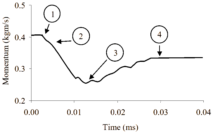
The momentum history of the steel tip penetrating a 6-mm 197 HV steel plate is shown below in Figure 6. The shape of the curve was fairly typical for all simulations however the rate of change of momentum increased with hardness indicating the increased level of resistance of the plate. At point (1), the tip comes into contact with crushed jacket material, it then proceeds to penetrate into it. When the jacket tip has been eroded, the hardened steel tip interacts with the EN8 steel plate (point 2). The steel tip continues to penetrate and be resisted by the target plate until there is insufficient constraint on the bullet, that is when the plate bulges and fails. The heavy core of the projectile continues to push the now-unconstrained tip through the plate (3). Eventually, both the tip and core emerge from the rear of the plate (4). In all simulations, very little deformation of the tip occurred.
Deformation to the core occurs by two mechanisms. First, the resistance to penetration offered by the plate on the tip pushes the tip back into the relatively soft core. This leads to an increase in the frontal surface area offered by the core to the plate. Second, the tip has formed a relatively small hole in the plate and therefore the relatively soft lead core interacts with the plate leading to its erosion. The jacket is stripped off the bullet and deposited on the inside of the hole.
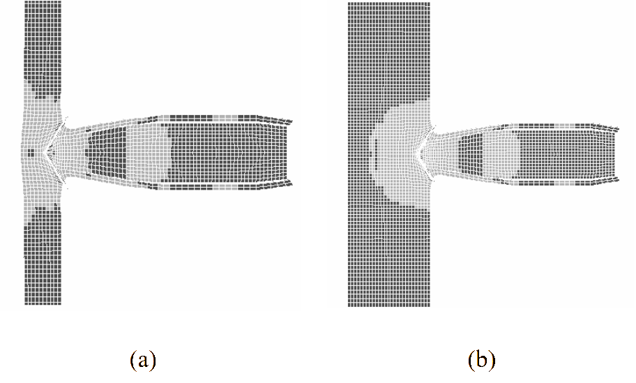
In evaluating the penetration resistance of a steel target, the major concern is the amount of work done in plastic deformation. Therefore the formation of the plastic zone ahead of the projectile plays an important role in resisting penetration. It also explains why the effect of hardness of the plate was more apparent with the thicker plates than for the thinner plates in both the experimental and numerical work. As the projectile penetrates each plate, the material ahead of the projectile (and the projectile itself) is work-hardened as per the Johnson-Cook constitutive relationship. Figure 7 below shows the effect of the plastic zone head of the projectile at 5 µs after impact. For the 3-mm plate the plastic zone has reached the rear surface of the plate and is extending laterally. With the 8-mm plate, the plastic zone is continuing to expand in a hemispherical fashion; at 5 µs after impact, the plastic zone is 5.97 mm into the plate. For a thicker plate the plastic zone ahead of the projectile is confined within the plate for a longer period of time, when the plastic zone impinges on the rear surface of the plate bulging begins and confinement is lost []. Harder thicker plates therefore offer a greater resistance to the projectile, deforming the lead core and thereby reducing the projectile’s kinetic energy density and hence its effectiveness. For thinner plates, the size of the plastic zone is relatively small and therefore the effect of the increased hardness is reduced. For all simulations, the rate of work hardening exceeded the rate of thermal softening.
Concluding remarks
Numerical models have been developed that simulated the penetration and subsequent perforation of heat-treated En8 plane carbon steel plate. Using quasi-static tensile test data and data from similar steels, the constitutive model was modified to accommodate two different hardness values. From the experimental work, failure of the plate occurred by ductile flow leading to bulging and ultimately petalling. Evidence of spall failure was apparent for the thicker harder plate (295 HV). In both the numerical and experimental programmes, the effect of increasing the hardness of the plate had a greater effect with the thicker plates and is due to the formation of a relatively large work-hardened zone ahead of the penetrator.
Acknowledgements
The author would like to acknowledge OCdt R. Hay and Capt R. Jeroma who did some of the background research upon which this paper is based. Thanks also go to Mr D. Miller who conducted the firings and to Mr N. Tiney from Century Dynamics for his assistance in compiling the user subroutine.