
Volume 5, Number 1, March 2002
Personnel Electromagnetic Radiation Hazards: An Introduction and Manpack Radio Issues
- 1 Antuition Enterprises, 4 Kipling Street, Moonee Ponds, Victoria, 3032, Australia.
Abstract
This article provides some insight into the complexity of the management issues associated with personnel electromagnetic radiation hazards (RADHAZ). The nature of the adverse effects of electromagnetic radiation on the human body is briefly discussed. The rationale behind the derivation of safe exposure levels is presented. Methods of estimation of specific absorption rate (SAR) are discussed, and data showing variation of SAR distribution within a standing body in a uniform field are illustrated. Computer modelling strategies for personnel RADHAZ investigations are discussed, including the creation of whole-body models, a methodology for manipulating body models to anatomically realistic stances, as well as the range of other factors and effects that need to be considered. Some images are included, showing computed field distributions from a generic manpack radio with the wearer standing and prone. An appendix discusses current personnel RADHAZ standards, policy and management within the Australian Defence Organisation (ADO).
Background
The increased use of electromagnetic emitters for communications and control has led to a corresponding increase in the strength and pervasiveness of the electromagnetic environment, both in Defence and civilian communities. Possible adverse effects on human health of exposure to electromagnetic radiation are of concern, particularly where levels may be sufficiently high to cause permanent damage. The increasing numbers of mobile phones, together with concerns of personnel hazards arising from exposure to electromagnetic radiation (personnel RADHAZ), has led to considerable effort being spent on the determination of field strengths and absorbed energy levels from such devices. Although the numbers are less, similar concerns arise from the use of manpack and other radio equipment by Defence personnel. Apart from legislative aspects, duty of care requires that such exposure is maintained below acceptable limits.
While the main thrust of media attention relating to mobile phones has focussed on possible development of brain tumours, a range of other responses have been attributed to different exposure levels. High field levels can cause death, burns, blindness and development of cataracts and tumours. Lower field levels produce more subtle effects including audible clicking, headaches and other discomfort, behavioural changes, short-term memory loss, as well as possible stimulation of changes at the cellular and DNA levels, which may provide a trigger for the eventual tumour development [1]. At these low levels, however, factors other than intensity can also have an important influence. These include the frequency, modulation and orientation of the field, the exposure regime, the latency period, and possibly the presence of toxins in the body, which may increase the predisposition of an individual to tumour development. At sufficiently low field levels tumour development may be slow or not occur at all. The question then arises as to what levels of exposure can be considered safe.
Both the mobile phone and the manpack radio present special problems as the source of radiation is in very close proximity to the body, and the fields are far from uniform. While numbers of manpack radios are less, concerns are similar and can be greater, particularly as nominal power levels up to 20W are available, rather than 1W or less for mobile phones. The nature of the interactions with the body is also different due to the different wavelengths involved.
Contrary to popular belief, the antenna is not the only source of radiation of a hand-held or worn transmitter such as a manpack radio. As the output signal is applied between the antenna and the case, the case is also part of the radiating structure. The wearer, being in close proximity to the case, is capacitively coupled to the case and as currents are coupled into the body, it becomes an extension of the radiating system. The whole (antenna, case and wearer) is in effect a vertical dipole antenna—the body, capacitively coupled to the case, becomes the lower element. If the wearer touches the radio case while it is transmitting, s/he will in effect be shorting out the body/case capacitance. If sufficient power is available (such as a nominal 20W from the RAVEN HF manpack), an arc can be drawn between the finger and the case, and a small burn may result. As the handset is connected to the case, an arc can sometimes be drawn from its metal fittings. Neither of these effects (the induced body currents and the arc) implies any defect in the equipment, but is a consequence of the wearer providing or modifying the current path from the radio set to the body, and thence to ground. The restricted space between the body and case is a region of high field gradients, and often exhibits the highest field strengths. Because of the restricted space and high field gradients, levels are difficult to measure directly, and other techniques such as computer modelling need to be applied.
Derivation of safe exposure levels
To better understand the effects of radiation, investigations continue into the relationship between exposure and adverse effects on the human body. Present epidemiological evidence does not imply causality between low-level exposure and adverse effects. Neither has it established the absence of any hazard. While the most evident effect of exposure is tissue heating, a number of other factors may be involved in eventual tumour development (see Figure 1). While these are masked at moderate radiation levels, they often result in conflicting results from studies involving low-level exposure. A thorough characterisation of low-level effects requires studies involving large sample sizes and long-term exposure, and a definitive answer cannot be expected in the short term. However, in the absence of substantive evidence that low-level exposures themselves produce adverse effects, exposure levels in most standards are based on the onset of perceptible temperature rise, where the results of studies become less ambiguous.
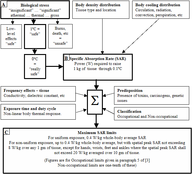
Figure 1 describes the rationale linking biological stress levels to the derived quantities generally accepted as a basis for personnel RADHAZ assessment. Box A (top left of Figure 1) categorises the level of biological stress in terms of electromagnetic exposure, ranging from “insignificant” to “significant”, levels below the threshold of thermal perception generally being agreed as being “safe”. Based on a safe tissue temperature rise and taking into account data on tissue density distribution and bodily cooling, a specific absorption rate (SAR) can be derived (Figure 1, Box B).
SAR is a measure of the rate of heat deposition in the body that will cause a given temperature rise in a specified mass of tissue, and is usually expressed in W/kg. Most standards are based on a temperature rise of one-tenth the threshold of perception, that is, 0.1º C. Tissue masses over which the SAR is averaged are typically between 1–10 gm. The exposure is generally averaged over a fixed period, typically six minutes.
In order to derive meaningful SAR limits for the whole body, a number of other factors need to be considered. These include:
- Frequency effects. Different tissues have different electromagnetic properties and will interact differently at the tissue level, absorbing more or less energy, as well as being more or less susceptible.
- Exposure time and duty cycle. If the exposure is intermittent, the body’s cooling mechanisms will be able to handle higher exposure levels, providing that the time-averaged SAR does not exceed acceptable levels. The cooling response of the body is non-linear with time, and also needs to be considered.
- Predisposition. There is some evidence that of the actions of small quantities of some toxins or carcinogens can be enhanced by electromagnetic stimulation. Generic predisposition may also modify the threshold of some individuals.
- Classification—occupational or non-occupational. Most standards distinguish between the general public who may not be electromagnetically aware, and those who work in an electromagnetic area and who are thus required to be suitably trained and aware of the hazards.
From considerations such as the above, maximum SAR limits are derived—the values given in Figure 1, Box C are taken from [3], and are included for information.
Measurement of SAR
Direct measurement of SAR is not a simple matter. Early methods involved the use of mannequins—physical replicas of part or of the whole body, and constructed from a range of materials intended to duplicate the body’s electromagnetic and thermal response. Embedded temperature-measuring probes provided direct measurement of temperature rise during exposure.
Recent advances include the development of shell models (phantoms) filled with tissue-simulating fluids with electromagnetic properties similar to that of an “average” human tissue (Figure 2).
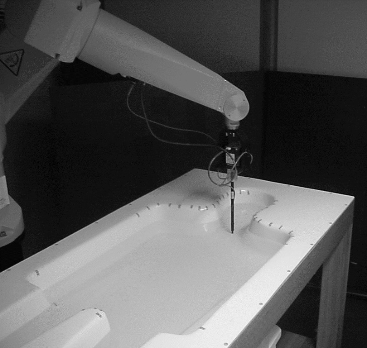
Field strengths are measured with a small probe moved through the fluid under precision computer control. Fields are measured over the region of interest, building up a three-dimensional map of field distribution. Using complex dosimetric calculations, SAR is inferred from the field measurements. The fluids, of necessity, are homogeneous and represent the average rather than the spatial tissue distribution of the human body. For both the mannequin and phantom models, currently available materials can only simulate average tissue parameters over a limited frequency range. Thus for measurements over a wide frequency range, a number of different materials (and models) must be used. Cost implications arise not only from the number of models or fluids needed to cover the frequency range, but from the need to recalibrate field strength probes for each particular fluid/material in use.
Because of the difficulties in direct determination of SAR, levels are generally inferred from measurements of incident electromagnetic fields, dosimetric calculations providing the link between the inferred SAR and external fields. The calculations rely on a thorough understanding of the coupling between an incident electromagnetic field, and the energy absorbed in the various tissues (that is, the heating), as well as how the tissues modify the field distribution both within the body and externally. Many factors need to be considered at the body level. These include:
- The frequency of the electromagnetic radiation. More energy is coupled into a structure that is resonant than one that is not. Apart from different frequency responses of various tissues (which are included in the determination of the SAR limits themselves), coupling to the body will also vary with frequency because of resonance effects. For a structure on or near the ground, coupling will be a maximum where the body height is close to an odd number of quarter wavelengths. Different heights and stances will alter the coupling and hence the SAR distribution and levels. The alignment between the polarisation (the direction of the electric field) and the major axis of the body will also effect how much energy is absorbed. With the body standing, coupling will be greatest when the electric field is aligned with the major axis of the body—that is, vertical polarisation. Figure 3 shows the variation due to resonance effects of body height of the whole-body averaged SAR under uniform exposure and with the body grounded. Because of resonance effects, the frequency for peak SAR decreases as the body height is increased. Similar effects also arise from height variation as the stance is changed.
- Environment. This includes the presence and type of ground, and nearby objects, both of which can modify the spatial distribution of electromagnetic field both outside and inside the body, and thus effecting the SAR distribution within the body. The ambient temperature must also considered an environmental effect as it will impact on the body’s ability to maintain body temperature within safe limits, and hence will have some effect on safe exposure levels.
![Variation of whole-body averaged SAR with phantom height, for an incident field of 1 V/m (derived from [4]).](/journals/journal-of-battlefield-technology/volume-05/issue-01/assets/5-1-3-nott/figures/figure03.png)
Based on considerations including those listed above, together with an estimation of the uncertainties arising from inferring SAR levels from electromagnetic exposure levels, derived safe levels can be proposed in terms of electric and magnetic field strengths, power densities, and body currents (Figure 5).
![Power absorption in body layers for a whole-body averaged SAR of 0.4 W/kg, at 30 and 120 MHz (derived from [4]).](/journals/journal-of-battlefield-technology/volume-05/issue-01/assets/5-1-3-nott/figures/figure04.gif)
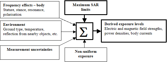
Because of the (apparent) ease of making electric field strength readings, this is the usual method adopted for personnel RADHAZ assessment. While direct measurements of field strengths can generally be made outside the body, because of high field gradients they cannot reliably be made in close proximity to radiating structures. Indeed, many exposure standards specifically exclude measurements within 20 mm of antennas and other radiating structures. Because of their construction, field strength probes inevitably perturb the fields they are measuring, and their physical size leads to uncertainties in where the field is actually being measured. These uncertainties become very significant in region of high field gradient, such as in the gap between the manpack radio antenna and the head, but more particularly, the radio case and the back and the body. Such investigations can often only be addressed by computer modelling.
Computer modelling
Computer modelling of electromagnetic effects has been available for many years, and can provide a valuable means of assessing exposure levels. Properly implemented, it can compute field strengths outside and inside the body, as well as the SAR, the basic quantity against which exposure levels are assessed. Figure 6 shows the main points that need to be addressed during computer modelling of personnel RADHAZ.
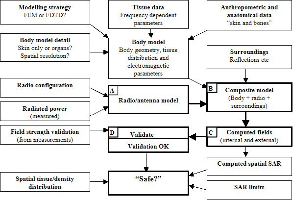
One of the first decisions that must be made is the choice of the mathematical modelling strategy. Two methods that are currently used are finite difference time domain (FDTD) and finite element analysis (FEM), each with its own strengths and weaknesses.
FDTD models consist large numbers of cubes called voxels, as illustrated in Figure 7. Each is assigned electromagnetic parameters appropriate to the type of tissue that the voxel represents. Building curved surfaces with cubes inevitably leads to a staircasing effect, but this is not a problem providing the voxel size is sufficiently small. In general, all voxels are the same size, although techniques are emerging whereby different size voxels can be mixed. This allows the complexity of the model to be reduced where detail is not required, or enhanced where greater detail is required. However, as the frequency is increased, smaller voxels are required to maintain adequate resolution at the shorter wavelength. So that fields outside the model itself can be properly established, a sufficiently large volume of “white-space” of voxels (not shown) must surround it. To simulate the model in an open space and so that boundary reflections are not produced, “energy-absorbing” voxels are needed at the boundaries of the problem space.
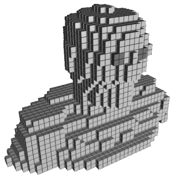
For mobile phone investigations, the head, neck and shoulders and the hand are often sufficient. However, for manpack radio investigations, as the wearer is an integral part of the antenna system, a whole-body model is required. Depending on the application, the frequency and the detail required, it may be sufficient to use a “skin-only” model filled with a material representing the average body parameters, or the model may include only the main organs, or include detail at the organ level. While a skin model could be created in a few weeks, inclusion of the internal structure increases this effort by many times. The method of creation will, of course, depend on the modelling strategy to be used.
Whatever type of model is created, it must necessarily be derived from proper anthropometric and anatomical data, which provides the basis for development of model geometry and assignment of appropriate electromagnetic parameters to model elements. As tissue parameters change with frequency, if wide frequency ranges are being considered, it may be necessary to create and link a database containing appropriate tissue parameters which is referenced each time the model is created for a new frequency.
For both the above modelling strategies, the inclusion of a surrounding “white space”, and non-reflecting boundary elements can add considerably to the volume that needs to be modelled. For models on or near the ground, additional model elements representing the ground are also required. While computer resources needed to run a whole-body model 176-cm high may not be a problem, addition of a manpack radio with a 3-m whip antenna can result in such a large increase in the problem size that computer resources may be severely strained, if not exceeded. Consequently great care needs to be taken in the design of models for such problems, and an often-difficult compromise made between element size, frequency and spatial resolution and computing resources.
The next concern is the radio equipment. This not only includes its configuration (antenna type, and how it is worn), but knowledge of the radiated power. In most cases, particularly the HF manpack, the radiated power is seldom what is ‘dialled up’, and measurements need to be taken across the band so that the model can be driven at appropriate excitation level. This involves the measurement of currents or voltages on an actual antenna, and not the power delivered to a 50-Ω load. To complicate the issue further, the radiated power will change with antenna loading and is thus a function of the radio configuration, the wearer’s stance, and to a lesser extent with the presence of nearby objects.
The body and radio models are merged to create a composite model. Unless a robust composite model is used (that is, one that is already validated), it will need to be validated before the results from modelling runs can be trusted. Most modelling programs provide some indication of how the model is running, whether the problem is ill-conditioned and thus likely to yield invalid results for the problem presented. Another validation issue concerns with whether the model actually represents what the modeller intends. One useful check involves comparison of computed fields with field-strength readings taken on an actual radio and wearer sufficiently far away from the system so that the fields are reasonably well behaved, and uncertainties are correspondingly low. If there is not reasonable agreement the modeller has the task of looking carefully at the model to try and identify the problem. This is generally more of an art than a science, and requires a thorough understanding of both the electromagnetic interactions and the limitations of the chosen modelling strategy and its implementation. Field strength measurement techniques should also be carefully scrutinised. The iterative path shown at the lower centre of Figure 6 (boxes A, B, C and D) represents these necessary validation steps. It is only after satisfactory validation is achieved that the composite model can be considered robust, and the results used in a personnel RADHAZ assessment.
From the computed spatial internal field distribution, the power absorbed by any volume of tissue can be determined. This, together with the spatial density distribution, allows the SAR in the region under consideration to be calculated, which can then be assessed against the specified maximum SAR levels.
Early computer models of human geometry used generic primitives such as prolate spheroids (egg-shapes) or simple boxes. Advances in computer size and speed have led to the development of more realistic models. Dimbylow [4] describes recent work based on an anatomically realistic model comprising a large number of voxels, each assigned the appropriate electromagnetic parameters for one of 27 different tissue types. The voxel size for the adult phantom is 2-mm cube, and the total number of voxels is approximately nine million. This phantom is scaled to agree with the height (176 cm) and mass (73 kg) of the reference man of the International Commission on Radiological Protection (ICRP) and is known as “NORMAN” (normalized man).
For such models, the tissue distribution within the phantom is derived from data obtained from techniques such as magnetic resonance imaging (MRI). Another source is the “Visible Human” project [5]. At the other extreme, some work, including that commenced at the Australian Army’s Land Engineering Agency (LEA) used anatomical data such as that in [6], first published at the beginning of the twentieth century, the body data being obtained by manual tracing of physical cross-sections of cadavers.
Computer modelling, particularly with the speed, resolution and fidelity that is becoming available, offers a most useful method of investigating SAR distributions under different conditions. As well as the determination of whole-body average SAR, spatial distributions of SAR can be obtained down to voxel resolution. Such models can also be scaled so that effects of stature can be readily investigated. The complexity of such models can be appreciated from Figure 9, which shows two sagittal (that is, vertical, along the front/back direction) slices of NORMAN. Creation of anatomically realistic accurate whole-body models involves a very significant investment in time and effort, and is definitely not an area for the beginner.
![Sagittal slices of NORMAN (derived from [4]).](/journals/journal-of-battlefield-technology/volume-05/issue-01/assets/5-1-3-nott/figures/figure09.png)
Figure 10 shows the SAR distribution at 120 MHz within NORMAN for the same two cross-sections as in Figure 9. The exposure is a uniform vertically polarised plane wave incident on the front of the body, and at a level equivalent to a whole-body average SAR of 0.4 W/kg. As the absorbed power is proportional to the square of the current density, narrower sections such as the neck, ankles and knees will exhibit correspondingly higher current densities and SAR values. Moreover, these regions comprise mainly low-conductivity tissues (bone and tendon with little muscle), and this further increases the SAR. At 30 MHz, where the current is greatest near the feet (see Figure 4), maximum layer absorption occurs at the ankles and to a lesser extent at the feet. At 120 MHz, the peaks occur in the neck and abdomen, and not in the ankles.
![Power absorbed in 6mm voxels for a uniform plane wave exposure at 120 MHz of a grounded adult phantom (derived from [4]).](/journals/journal-of-battlefield-technology/volume-05/issue-01/assets/5-1-3-nott/figures/figure10.png)
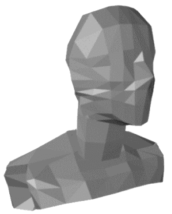
Computer models of the body are generally based on anatomical data derived from body cross-sections sections representing the standing position. Currently available model-creation environments do not allow the model to be manipulated into a difference stance while maintaining anthropometric fidelity. As a consequence, for each different stance (sitting, squatting, prone, and so on) the body model must be re-created, requiring many weeks of work. And while it is difficult enough to create models in the same stance as the data from which they are derived (that is, standing), a different stance involves the additional complexity of remapping of the tissue data into its new location. In 1999, the author devised an efficient method to perform this data manipulation accordance with realistic anthropometric restraints. The method starts with the one-time creation of a composite model comprising a skeleton and the required body data. The skeleton is kinetically linked, and restrained by anthropometric joint data (limits of angular of movement, joint stiffness, and so on), derived from an authoritative source (Figure 11). A series of mesh elements representing the body (skin only or including internal organs) are created and overlaid and linked to the appropriate skeleton members. Skin and tissue data for such models is derived from data such as that shown in Figure 12, which shows a body cross-section taken from [6]. Because of the linkage between the skeleton and the body elements, movement of the skeleton members (Figure 13) causes a corresponding movement in the body elements (Figure 14). The vertex data for the body elements in their new positions is then written to an external file and post-processed to maintain mesh continuity across joints, adding stretching where required. The resulting geometry is then used to re-map tissue locations, creating a body model in the new stance in the space of a few minutes. Model creation, of both the skeleton and the body, as well as the kinetic linking and manipulation of the resultant composite body is performed in 3D Studio® Version 4, a rendering and animation package.
![Body segment parameters (derived from [7]).](/journals/journal-of-battlefield-technology/volume-05/issue-01/assets/5-1-3-nott/figures/figure11.png)
![A cross-section through the region of the stomach (derived from [6]).](/journals/journal-of-battlefield-technology/volume-05/issue-01/assets/5-1-3-nott/figures/figure12.png)
![Kinetically linked skeleton derived from body data in [7].](/journals/journal-of-battlefield-technology/volume-05/issue-01/assets/5-1-3-nott/figures/figure13.png)
![Skin-only mesh body derived from data in [6].](/journals/journal-of-battlefield-technology/volume-05/issue-01/assets/5-1-3-nott/figures/figure14.png)
These techniques were foreshadowed in a paper [8] delivered at the Applied Computational Electromagnetic Society’s (ACES) review of progress in March 2000. The paper aroused considerable interest within the ACES bio-electromagnetic modelling community, but unfortunately LEA support of this work was withdrawn early in 2000. So that the methodology would not be lost, it was fully developed by the author in his own time, and a second ACES paper [9] was presented in 2001.
LEA modelling
Prior to the development of the more detailed body models shown in Figures 13 and 14, LEA was using a simple body model with a fixed stance. To this was added a model of a generic manpack radio, implemented as a rectangular box, a two-metre antenna, and its excitation. Initial modelling of field distributions around and in the body was commenced. Because no data was available on the actual radiated power from these radios, the results could not be extrapolated to actual exposure levels. The results, however, do give some insight into distribution of fields around the body, and to a limited extent can give some insight into the effects on exposure level arising from posture changes. This work suggests that at some frequencies, exposure levels could be higher when the wearer is squatting or prone, than when standing.
Figure 15 shows the field distribution from a manpack radio with a 2-m whip at 10 MHz, 30 MHz and 80 MHz. Fields are plotted on a plane passing through the gap between the radio set case and the wearer’s back. While there is some field associated with the antenna, the greatest field strengths occur in the region between the radio+antenna and the body. Although they are greater, fields at 30 MHz show a similar distribution to those at 10 MHz. At 80 MHz the standing waves on the antenna+body structure are evident as the nodes (minimum fields) at the hips and part way up the antenna. Field minima are also present in the surrounding air-space on a level with the chest and the top of the antenna. While the field distribution from a manpack radio is non-uniform at all frequencies, these images demonstrate the significant non-uniform field distribution from the manpack radio as frequencies are increased.
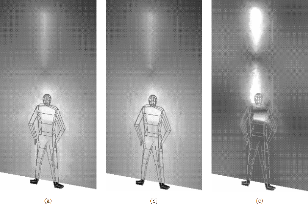
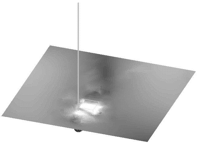
Figure 16 shows the field enhancement with the wearer lying on the ground. Fields are shown on a plane that passes through the gap between the radio case and the wearer’s back. As expected, the ‘hot-spot’ is generally limited to the area of the radio case and at the base of the antenna. The wearer’s head is just visible near the centre of the lower edge of the field plot.
Initial LEA investigations into exposure levels from manpack radios suggest that for some frequencies at least, levels may be greater for other postures than for standing erect. A significant amount of modelling work needs to be done before this and other aspects of manpack radio exposure are adequately characterised. Until this is done, to ensure that mandated exposure levels are not exceeded, it is understood that some restrictions have been applied to transmission from manpack radios while they are being worn.
Conclusions
A wide range of complex issues relating to personnel radiation hazards has been addressed. These include the nature of exposure hazards, current ADO personnel RADHAZ management policy, the derivation of safe exposure levels, and assessment processes. The complexity of the personnel RADHAZ assessment has been illustrated, including the range of external factors that can modify exposure levels. Computer modelling strategies and model creation issues has been discussed, together with some of the techniques developed and results obtained from modelling commenced at LEA. The LEA modelling was initiated to address issues of exposure from manpack radios, in particular the effects of changes in stance on exposure levels. Further detailed investigation is needed to fully characterise manpack radio exposure, which will allow better personnel RADHAZ management.
Appendix One: Australian Defence Personnel RADHAZ Management
Current standards and policy
The standard currently adopted within Australia for personnel exposure to electromagnetic fields is AS2772.1(int) [3]. This is an interim Standard that expired in February 1999, but because failure to reach agreement on a number of issues has delayed the issue of a new standard, it is still in use. The Australian Radiation Protection and Nuclear Safety Agency (ARPANSA) has developed a draft Standard for maximum exposure levels [10], which was issued for public comment in March 2001. The levels in this draft are based on the guidelines of the International Commission in Non-Ionizing Radiation Protection (ICNIRP) committee [11] and it contains excellent background and reference material on personnel RADHAZ issues. Reference [10], if adopted, will make some changes to these levels, principally:
- The spatial peak SAR has been increased from 8 W/kg to 10 W/kg for occupational exposure, and from 1.6 W/kg to 2 W/kg for non-occupational (public) exposure.
- The averaging tissue mass has been changed from 1 gm to 10 gm.
- The averaging time, originally six minutes, is now frequency dependent, reducing below six minutes for frequencies above 10 GHz.
While the revised levels will allow an effective increase in the maximum exposure levels above those in the currently adopted Australian Standard, they are in accord with the levels of [11].
ADO policy on electromagnetic radiation safety management is contained in DI(G)-PERS 19-3 [12], which has recently been significantly revised from its 1992 issue. It covers a number of issues including roles and responsibilities, training and education, and overexposure reporting and investigation requirements. In particular it sets out procedures to be adopted within the ADO to ensure due diligence in the management of personnel radiation hazards. It defines RF radiation safety policy for the whole of the ADO and provides practical guidance on which the ADO Group Heads can base their respective RF Radiation Safety Management Programs—specifically:
“ADO Group Heads are to ensure that:
- an RF Radiation Safety Management Program is implemented within their respective Group, which satisfies or exceeds the requirements of this Instruction;
- suitable delegates are appointed from their Group to the RFRSS; and
- all RF safety aspects of platform integration are addressed.”
Personnel RADHAZ surveys
Unless safe levels of electromagnetic exposure can be demonstrated by other means, personnel RADHAZ surveys are required. These involve measurements of electromagnetic fields in the area of concern. Because of legislative requirements to ensure a safe working environment, measurements must be authoritative. Thus personnel undertaking personnel RADHAZ surveys are required to be appropriately trained and currently certified, measurement equipment properly calibrated and all measurements traceable to an appropriate standard.
Fleet In-Service Trials (FIST) is an element of the Surface Combatant Force Element Group within the Royal Australian Navy (RAN). FIST are responsible for conducting pre- and post-refit trials on ships in the RAN as well as conducting personnel RADHAZ surveys for all ships and shore establishments. Personnel who conduct these surveys are trained as Radiofrequency Radiation Safety Officers (RFRSOs) by TELSTRA or the Australian Defence Force Academy (ADFA). These courses are conducted to enable the attendees to use current best practices to ensure that the measurements taken are both accurate and reproducible.
Army and the Royal Australian Air Force (RAAF) do not have an equivalent element to FIST to conduct personnel RADHAZ surveys, and will generally task services from FIST. As FIST is not funded to conduct these surveys, they will be on a “user pays” basis.
A variety of measurement equipment is available to measure field from both continuous (radio) and pulsed (radar) sources. These include hand-held meters, peak-power meters and associated antennas. FIST currently has an ability to measure fields at frequencies from 50 Hz through to 18 GHz, however this will be increased to 40 GHz in the near future.
The current procedures for ensuring calibration of the equipment are coordinated through the Australian defence Force (ADF) Calibration Centre. Equipment is sent to recognised calibration facilities in Australia, the procedure generally taking 4-6 weeks; however on occasions it has taken up to three months. Within Australia, calibration can only be performed at the limited range of frequencies. While overseas centres can provide calibration at a greater number of frequencies, this is not generally feasible due to the lengthy turn around time and the substantial cost involved.
Acknowledgements
Permission from Dr Peter Dimbylow and the UK National Radiation Protection Board to use material from [4] is gratefully acknowledged.
Thanks also go to Dr Mike Ryan of the School of Electrical Engineering, ADFA for his encouragement for the preparation of this document.
The proof-reading as well as the invaluable advice and comments of Mr Michael Michaliades, Human Factors Specialist, LEA, during the preparation of this document is greatly appreciated.
References
[1] S. Barnett, Status on Research on Biological Effects and Safety of Electromagnetic Radiation: Telecommunication Frequencies, CSIRO Division of Radiophysics, Ultrasonics Laboratory, 1994.
[2] S. Malcolm, R. Armstrong, M. Michaliades, and R Green, “A Thermal Assessment of Army Wet Weather Jackets”. International Journal of Industrial Ergonomics, Vol. 26, pp. 417-424, 2000
[3] Standards Australia AS 2772.1 (Int), Radiofrequency Fields—Part 1: Maximum Exposure Levels—3 to 300 GHz, 1998.
[4] P. Dimbylow, “FDTD Calculations of the Whole-body Averaged SAR in an Anatomically Realistic Voxel Model of the Human Body from 1 MHz to 1 GHz”, Phys. Med. Biol., Vol. 42, pp. 479-490, 1997.
[5] U.S National Library of Medicine, 8600 Rockville Pike, Bethesda, MD 20894, The Visible Human Project, http://www.nlm.nih.gov/research/visible/visible_human.html.
[6] Ecyleshymer and Schoemaker. A Cross-section Anatomy, D. Appleton and Company, 1970.
[7] Henry Dreyfus Associates, The Measure of Man and Woman, John Wiley and Sons Inc, 1993.
[8] A. Nott, “Modelling of Personnel Electromagnetic Radiation Hazards”, Proceedings of the 16th ACES Review of Progress, Monterey, CA, USA, Vol. 1, p. 325, March 20-24, 2000.
[9] A. Nott, “A Method of Creating Whole-body FEM Models Which are Adjustable to Different Postures”, Proceedings of the 17th ACES Review of Progress, Monterey, CA, USA, p. 164, March 19-23, 2001.
[10] Australian Radiation Protection and Nuclear Safety Agency (ARPANSA), Proposed Radiation Protection Standard, Maximum Exposure Levels to Radiofrequency Fields—3 to 300 GHz, http://www.arpansa.gov.au/pubs/d_rf_prot_stnd.pdf.
[11] International Commission on Non-Ionizing Radiation Protection (ICNIRP), Guidelines for Limiting Exposure to Time-varying Electric, Magnetic and Electromagnetic Fields up to 300 GHz, http://www.icnirp.de/Documents/Emfgdl.PDF, 1998
[12] Defence Instruction DI(G)-PERS 19-3, Radiofrequency Radiation Radiation Safety Management in the Australian Defence Organisation, Defence Safety Management Agency (DSMA) web site, http://dsma.dcb.defence.gov.au/, under "What's New”.
This document was prepared as a private venture by Antuition Enterprises to record and consolidate work performed by the author both at LEA and privately.