
Volume 4, Number 3, November 2001
Options for the Defeat of Solar Blind Ultra Violet Wavelength Missile Warning Sensors
Abstract
Recent conflicts have demonstrated that the threat from Infrared (IR) Seeker Surface to Air Missiles (SAMs) is significant. Air operations in Bosnia and Kosovo were severely hampered by the requirement to fly above the maximum engagement range of SAM systems. In particular, the threat posed by highly mobile, easily concealed Shoulder Launched SAMs limited the use of low-level reconnaissance, attack helicopters and offensive air support. The development of the passive Missile Warning Sensor (MWS) has been seen as a way of redressing the aircraft-missile engagement balance by offering to re-establish the validity of safe flying operations at low level. Unfortunately, testing of Defensive Aids Suites (DAS) employing MWS technology indicates that there are many problems associated with the integration and operation of a missile detection, warning and engagement system. The paper outlines the technology and deployment doctrine associated with the MWS and provides options that the IR Seeker SAM designer and/or operator could utilise to overcome MWS-based DAS.
Introduction
The threat to military aircraft from surface-to-air missiles (SAM) has significantly increased in recent years. Technological developments in the fields of telemetry, sensor and control systems have ensured the rapid and continued evolution of missile systems technology. The proliferation of missiles employing passive infrared seeker technology amongst ‘rogue nations’ and terrorist organisations make these missiles the most significant threat to a combat aircraft.
The Ir Threat
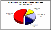
In order to view missile engagement data across a broad spectrum of conflict types, a review of successful engagements between 1981 and 1998 has been carried out, and this further supports the view that both SAM and air-to-air missiles (AAM) have become the weapons of choice against air targets.
As can be seen from Figure 1, the threat from IR SAM systems is considerable and with continuing missile development, is likely to be maintained. For this reason the development and fielding of a fully capable Defensive Aids Suite (DAS) is deemed essential for future aircraft protection.
DAS Development
Missile development has accelerated in recent years, in part due to advances in technology but also due to their excellent performance in combat. Analysis of successful engagement data shows that the improvements in shoulder-launched (SL) systems, where mobility and ease of operation are paramount, have led to their proliferation. Indeed, it is often quoted that organisations such as the IRA have been equipping themselves with SLSAMs. Systems such as STINGER and SA-18 have revolutionised SAM engagements such that where possible, aircraft combat missions are flown above the ceiling of SLSAM systems, as shown recently by NATO in Bosnia and Kosovo.
In an effort to redress the balance between the aircraft and the missile, research into systems that could be utilised to defeat SAM/AAM systems has been widespread. The development work has followed two main paths:
defensive systems such as flares, chaff and towed decoys; and
active systems such as jammers and hard-kill systems.
Defensive Systems
Until the development of IR detector technology in the late 1940s, the only effective aircraft detection system was RADAR. As such, advances in aircraft defensive systems have developed from radar-decoying metal chaff, as used in the 1940s, through to state-of-the-art towed electronic warfare decoys, successfully utilised against modern radio frequency (RF) seeker systems as deployed during the Gulf War. The latter is an active RF radiator that is either turned on at a particular pre-set location/time or initiated by on-board warning sensors. These systems are reactive to the threat of a missile and aim to decoy the missile away from the aircraft onto a locally more powerful emitter/radar reflector, located at a safe distance from the aircraft itself. One feature of their use however, is that deployment of the decoy actively promotes the location of the aircraft, often cueing the deployment of other, possibly more effective, weapon systems.
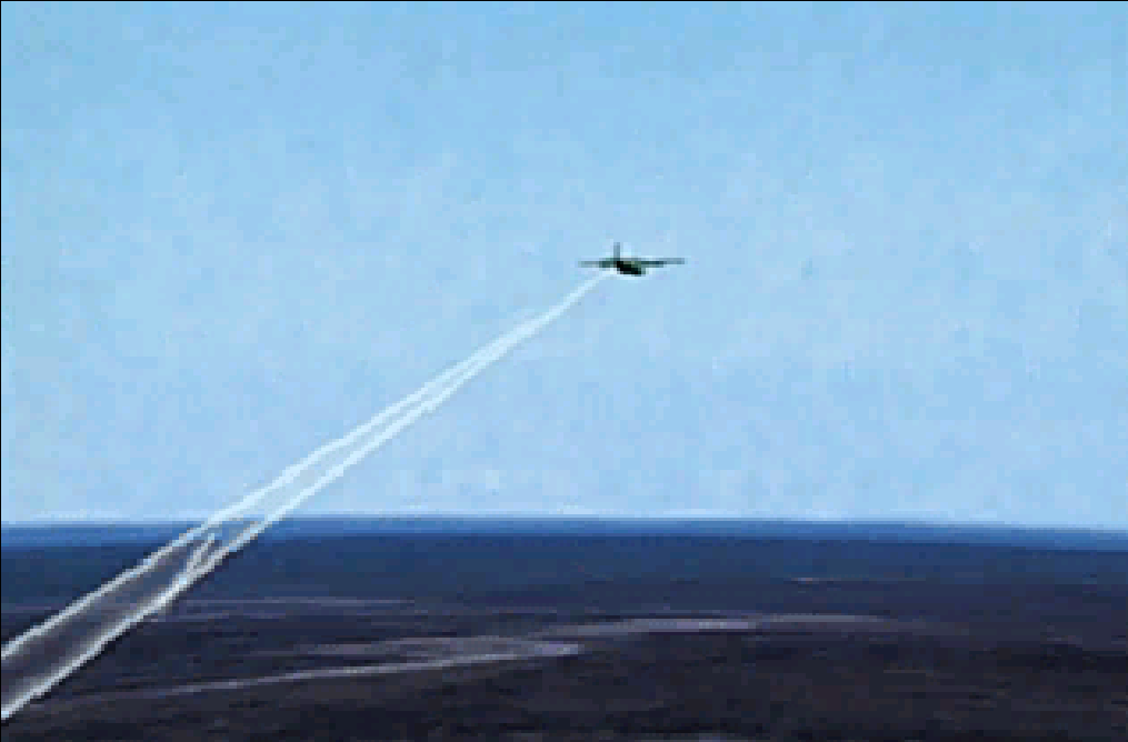
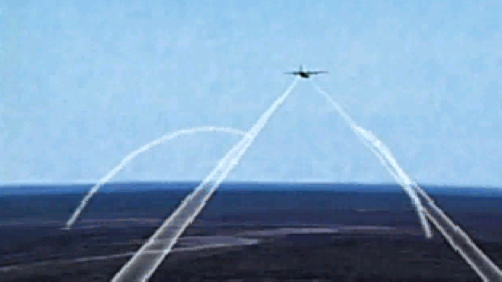
Perhaps the most successful defensive system ever deployed has been the IR flare. The IR flare is used to seduce an IR seeker away from the target by having a higher signature than that of the target itself. Such flares have great utility against early generations of IR missile systems. Flares are traditionally used in one of two ways: timed deployment or deployment triggered by missile approach sensors. In each case, a number of flares are usually deployed in order to provide coverage over the majority of missile approach profiles. However, multi-deployment of flares has significant signature implications, as shown in Figure 2.

Active Systems
Active systems are a more recent development, in particular those that involve specific engagement of the incoming missile. As their name describes, these systems actively seek out the missile and attempt to directly affect its operation either through jamming or physical damage. It is the operation and possible seduction of this type of system that is of particular interest to this paper.
Missile Warning Sensor
The Missile Warning Sensor (MWS) is the latest sensor to be included in the Defensive Aids Suite of modern aircraft. The sensor is designed to detect the launch plume of a missile and provide launch location information for the system that subsequently engages the missile. The MWS operates passively and is therefore capable of continuous operation without advertising the presence of the aircraft. In current systems, the missile launch data is passed to a fine-tracker that locates and tracks the missile trajectory. If the missile is on an intercept trajectory, the fine tracker engages its IR jammer, dazzling the missile’s seeker in order to achieve break-lock. Future systems are expected to utilise a laser to dazzle or damage the IR seeker in the missile [1].
The MWS can operate in the Solar Blind (SB) region of the spectrum, that is within the 230–280 nm wavelength band [2] and looks for SB-wavelength ultraviolet (UV) emissions, that may be present in missile exhaust plumes. Operating in the SB region rather than other regions of the electromagnetic spectrum is of particular significance as there is minimal natural background radiation ‘noise’ and as such, most SBUV emitters are man-made.
The Infrared Countermeasure (ircm) System
IRCM systems have been fitted to aircraft for some years. Until recently however, most have been IR jammers, emitting on command from the operator. Whilst they offered protection against early IR seeker technology, decoy rejecting multi-colour (multi-waveband) systems can overcome the decoy element of the jammer and actually lock-on to the source, dramatically improving their ability to engage the target.
The development of detectors and filters capable of eliminating radiation in all bands except the SB region offered new opportunities for the engagement of in-flight IR missiles. By passively detecting the launch of a missile the SBUV MWS is able to cue secondary (active) systems. The key advantage of this new development is the ability to scan passively the battlefield and only emit actively from the platform when a threat is detected, therefore greatly reducing platform vulnerability to ground-based sensors.
The DAS
A typical modern DAS may therefore be composed of several elements:
- a Missile Warning Sensor which detects the SBUV radiation and hands over coordinates;
- a fine-track system that tracks the missile either via its IR plume or its kinetic heating signature;
- a jammer to dazzle or damage the seeker of the missile—thus preventing a successful engagement;
- a central processor system that controls the above sequence and which also filters out known false alarm signals by the use of threat signature algorithms; and
- a missile direction indicator for the pilot, which indicates the location of the launch and whether the IRCM system is engaging the missile.
The following description outlines one possible solution for the integration of a DAS onto an aerial platform.
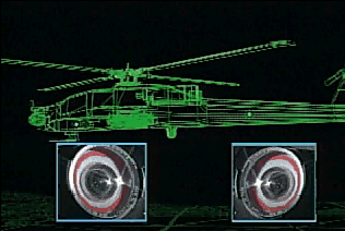
The MWS shown in Figure 3 are situated on the aerial platform in order to ensure complete missile approach coverage. These cue the Missile Fine Optical Tracker (MFOT) onto the missile approach direction. The MFOT tracks the missile by its thermal signature. This has two elements: one due to the boost/sustain rocket motor and a second, of lower intensity, caused by kinetic energy heating of the front of the missile due to frictional effects of the atmosphere on the leading surfaces.
more of its MWS and sends very precise launch co-ordinates to the central processor, which then feeds the information into the MFOT (Figure 4), which slues onto the target location and then tracks the trajectory of the missile. If the missile’s trajectory intercepts that of the air platform, the tracker initiates the IR jammer to dazzle or damage the missile’s seeker in order to achieve terminal break-lock. If achieved, the missile will then be directed away from the air platform. This process is continued until there is no possibility of target reacquisition by the missile’s sensor.
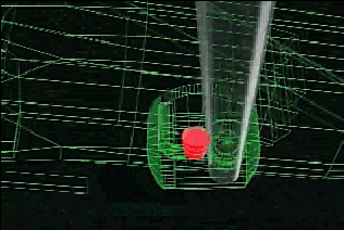
The DAS detects the launch signature of a missile in one or
The following shows the detection, engagement and subsequent defeat of an IR missile in the usual sequence.
The IR SAM is launched and the boost motor signature is detected by the UVMWS (Figure 5).
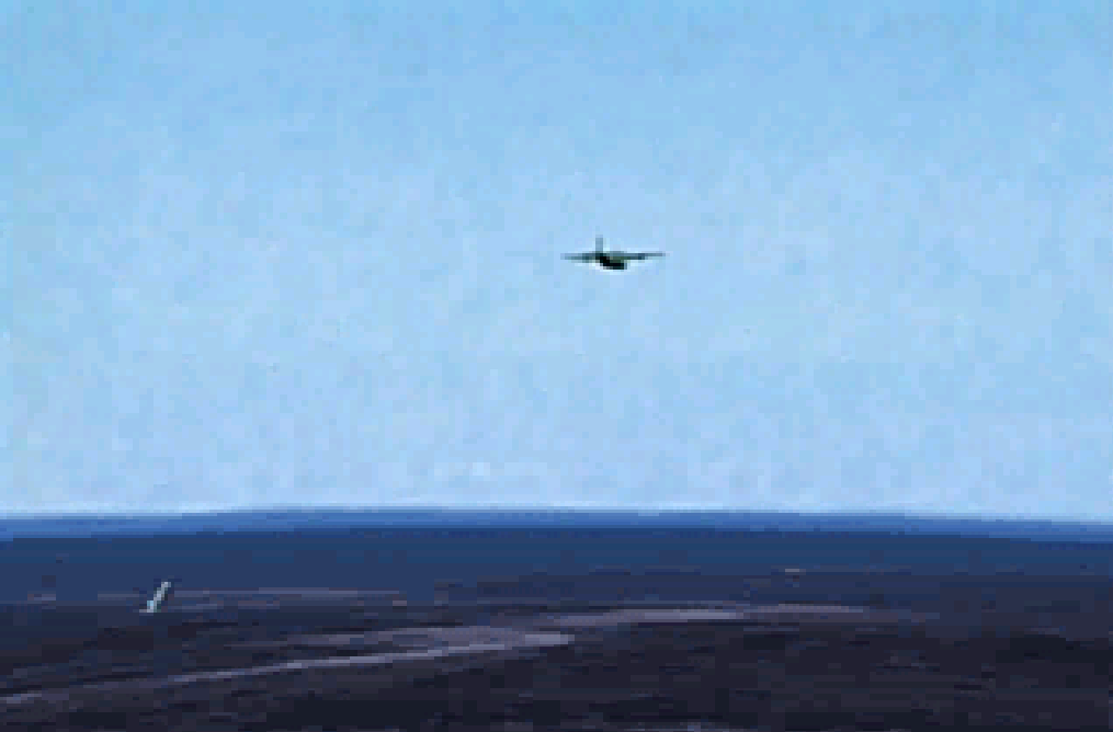
The target missile coordinates are then handed over to the MFOT (Figure 6).
The MFOT acquires the missile and monitors whether it is on an intercept trajectory. If so it prepares to engage the missile. Having acquired the missile and identified an intercept profile, the missile is then engaged with the IR jammer. If this is successful the missile looses lock and heads away from the aircraft. A second missile is detected, tracked and engaged by the IR jammer.
If two trackers are fitted then two simultaneous engagements are possible if each missile is in the field of view of a different tracker as each tracker/jammer can only engage one missile at a time. It is likely that larger aircraft, such as transports, will be fitted with a dual system.
One of the key elements in the DAS is clearly the MWS, which cues the remainder of the system onto the target. Defeating the MWS is therefore an effective option when countering a modern DAS.
Options for the Defeat of the Missile Warning Sensors
Aircraft Approach to Missile Firing Post [3]
In order to successfully engage an aircraft equipped with a SBUV MWS, it is essential to have an understanding of the aerial vehicle’s likely attack profile if optimum siting of air defence (AD) assets is to be achieved. Attack from the air is usually driven by three factors: the air system undertaking the attack, the target type and finally the target’s environment and geographical location. Current UK MoD doctrine states that the main threats a shoulder launched SAM could be expected to engage are: fast transiting Fighter Ground Attack (FGA) aircraft at 300 m/s, manoeuvring Ground Support Fighters (GSF) at 200 m/s and fast Attack Helicopters (AH) at 100 m/s. Having identified the air vehicle of interest, the drivers of ‘target type’ and ‘environment and terrain’ dictate the munition deployment profile used by the aircraft.
Fixed Wing Aircraft Attack
Aircraft could use one of the following attack profiles:
Laydown Attack. The aircraft flies, at low level, directly to its target and weapons are released at low level— 100 m altitude and 600 kts.
Offset and Pull-Up. Maximum use of terrain features to minimise exposure until the last minute when the aircraft climbs, turns and then dives towards the target.
High Level, Toss or Loft Bombing. This is a pre-planned means of weapon delivery allowing the aircraft to attack from considerable range.
Dive Attack. This is usually used against opportunity targets, using a shallow dive, directly towards the target, from the cruising altitude.
Helicopter Attack
Helicopters could use one of the following profiles:
Anti-Armour Operations (AAO). Standoff attack of targets from a flank at long ranges. Aircraft usually attack from the hover or at slow forward speeds.
Offensive Air Support (OAS). Utilisation of rockets, cannons and machine guns out to ranges of 3000 m both in the hover and during approach manoeuvres up to 150 kts.
Deployment Doctrine
Currently, doctrine developed for the SLSAM systems operated by the British Ministry of Defence is optimised to engage the attacking aircraft at maximum range. The use of late unmasking techniques, terrain following approaches and stand-off deployment of munitions, requires the defender to deploy well forward to the likely target area if a successful engagement is to be achieved. One major factor in the effective deployment of a SLSAM is correct identification of the aircraft’s Line of Weapon Release (LWR) (the point at which the munition is released from the aircraft). Engagement of the aircraft after this occurrence is unlikely to prevent the impact of the munition on the target (the Vital Point VP for Point Defence) as shown in Figure 8.
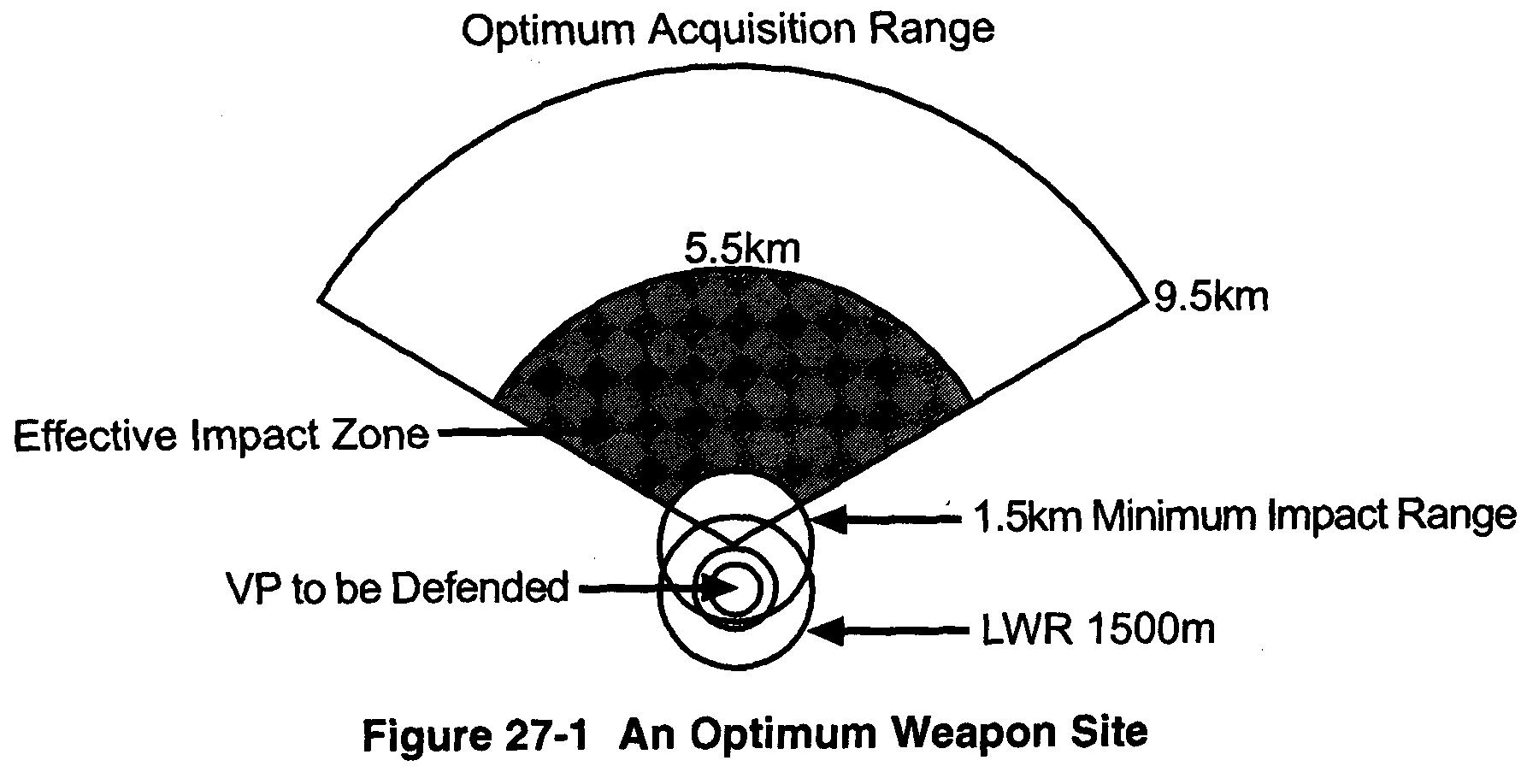
Current deployment directives require the SAM system operator to trade off between effective field-of-view (and hence target detection range) and camouflage. UK SLSAM system operators are required to optically detect the target (if not using the Air Defence Alerting Device), sight the missile’s optics and then fire the missile. In order for this process to be effective, it is essential that the missile system be brought to bear on targets rapidly and, where possible, at long range in order to maximise the probability of a successful engagement.
As ideal sites are not always easy to locate, alternative sites requiring compromises may be selected. These will either have reduced maximum effective acquisition ranges or suffer from some form of field of view (FOV) restriction in one or more sectors.
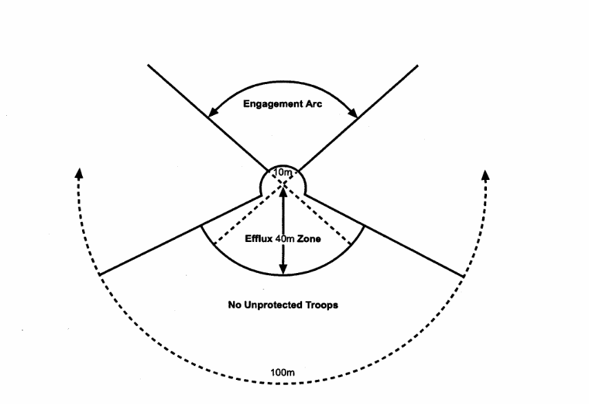
As well as the tactical siting drivers imposed on the system operator, the missile system itself may impose limits due to rocket motor efflux. Figure 9 is an example of how missile rocket motor design may affect siting.
Tactical Deployment
From the above brief overview of firing post siting, it is clear that detection at maximum range, recognition and identification well before the LWR should enable high single shot kill probabilities (SSKPs). As the UK rarely operates SLSAM firing posts in isolation an overview of multi-post deployment is desirable. The deployment of several firing posts in order to afford an improved detection FOV and hence improved engagement probabilities is shown in Figure 10 where VPA is the visual priority arc and FU is the fire unit.
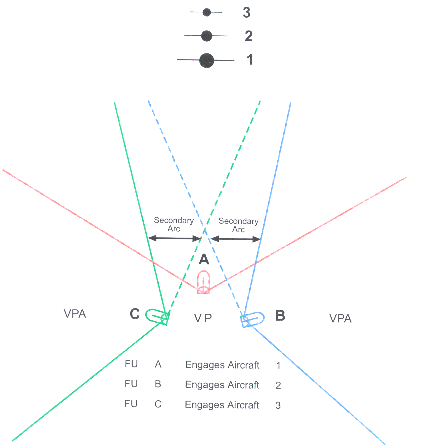
A multi-post deployment can therefore increase the firepower of the AD structure by using interlocking arcs of fire.
Operational Implications of SBUV MWS
The current UK deployment doctrine was generated before the emergence of in-service DAS and whilst the majority of the UK’s surface to air systems do not utilise passive homing IR seeker missiles, the ability of a DAS to detect a hostile launch is still significant for the survivability of the airframe. As stated previously, DAS currently engage IR seekers with IR jammers, however, laser developments are ongoing to incorporate a dazzle or damage system as and/or when appropriate. Hence, it is imperative that the UK investigates the effect of the introduction to service of DAS and revises current doctrine.
Unfortunately, current UK siting/deployment doctrine increases the likelihood of a target equipped with a DAS successfully detecting a hostile missile launch and engaging it, especially if the missile uses an IR seeker. In order to redress this, shoulder launched missile systems need to evolve methods of defeating the SBUV MWS of the DAS.
Defeating DAS
There are several methods that could be employed in order to defeat the DAS:
Camouflage Weapon System. Prevent detection through effective use of materials, clever use of terrain or natural cover. Of particular significance will be the development of systems capable of being fired from within enclosed spaces such as rooms and bunkers.
Camouflage Efflux. The scattering and absorption of SBUV radiation in the atmosphere is quite severe. Hence if the SBUV emitted intensity of a missile plume can be minimised through the manipulation of the chemical construction of the propellant, or masked in some manner, the range at which a MWS will detect a missile plume at launch will also diminish.
Disguise Efflux. If the efflux thermal signature was manipulated it may be possible to move the thermal spectrum out of the sensors pass band wavelengths—thus, to the sensor, the efflux would be invisible.
Jam Efflux Thermal Signature. If the efflux was emitted with a thermal scatterer, such as particulate smoke, the sensor may not be able to detect the efflux.
Replicate Thermal Noise. If the efflux signature was carefully manipulated so that, when detected, it replicated either a known false alarm UV source or a friendly forces weapon system, the DAS would not engage the missile
Each of the above options offers a potential method of defeating an MWS-alerted DAS and several are expanded upon in more detail below.
Camouflage Launch Locations
Currently, operators view camouflage as an important way of disguising the location of the system’s position prior to engagement. Hence, it is usual for the operator to dig a protective trench, cover his equipment with easy-to-remove netting or natural camouflage and utilise the ground to best advantage. Unfortunately, as already highlighted once the system is brought into operation, it is essential that good firing arcs are available for optimal engagement, especially for fast moving agile/crossing targets. To achieve this, there must be only limited close clutter within these arcs.
Based on current doctrine, it is unsurprising that most shoulder launched systems are located away from trees, small bushes and often on raised ground. In fact, the tactical situation may require the operator to locate on high or often open or exposed positions. In the visible spectrum, these locations are easy to camouflage as described above until the system is fired. Unfortunately, as the missile is fired, the plume is exposed against a low clutter background, making detection and possible identification by the target’s MWS simpler. Currently, the physical properties of the exhaust gases preclude operation from bunkers/hard shelters and require rearward clearance from foliage etc, in order to prevent injury to the operator or fire.
Reviewing the current operating parameters indicates that, unless the energy of the efflux can be significantly reduced and the engagement profile dramatically altered, there is little the operator can implement to change the current deployment doctrine.
Plume Reduction
Another approach is to reduce the probability of plume detection or, if the plume is detected, prevent identification of the plume as a SLSAM rocket motor. Looking firstly at plume reduction, there are several methods that could be employed:
Reduce Thrust Level of Missile. The radiant intensity of a missile plume is directly proportional to the thrust generated. Hence by reducing the thrust required to correctly operate the missile, the detection range will also reduce. This raises quite significant problems for the designer, as range, speed and agility are all factors driving the thrust level required.
Prevent Plume Gas Re-ignition. Re-ignition of the hot gases, generated by the rocket motor, on contact with the atmosphere is a significant contributor to the SBUV emissions. The inclusion of flame suppressants in the rocket propellant can dramatically reduce the probability of re-ignition, however, this is at the cost of increased smoke in the plume. Thus, whilst the UV signature is reduced, the visual signature increases.
Introduction of In-Plume Absorbers. If particles specifically designed to absorb SBUV radiation at the problem frequencies can be generated in the motor efflux, the intensity of the emitted radiation will reduce. This will again increase the visible signature of the missile plume.
Identification Confusion and Clutter Effects
In addition to missiles, there are likely to be many other SBUV emitters on the modern battlefield. The main armament of MBTs, tracked artillery and larger solid rocket motor driven missile systems all have SBUV signatures. With the exception of isolated terrorist attacks or small conflicts, it is likely that the modern battlefield will be an UV cluttered environment, within which the MWS will have to accurately identify SAM plumes from other clutter. By replication of known SBUV sources it should be possible to mask the launch signature of future SAM systems [4].
Summary
Defeating a MWS requires knowledge of the capabilities of the MWS as well as an understanding of the operating characteristics of the SAM being used. Detailed investigation of the operational impact of the introduction to service of MWS-driven DAS is imperative if the effectiveness of SLSAM systems is to be maintained.
Acknowledgements
Figures 2-7 are reproduced here by kind permission of DHSA, Yeovilton, United Kingdom. The information obtained in Figures 8-10 is by kind permission of HQ-Directorate, Royal Artillery, Larkhill, United Kingdom.
References
[1] AN/AAQ-24 (V) Promotional CD ROM, Northrop-Grumman/GEC Marconi ARI 18246, by kind permission DHSA, Yeovilton.
[2] R. Lowe and Z. Kucerovsky, A Survey of Solar-Blind Ultraviolet Technology, Final Report 8SR79-00022, Physics Department, University of Western Ontario, Canada, March 1980.
[3] Air Defence Organisation Deployment and Operating Procedures (ODOPs), Artillery Training Volume IV Air Defence Artillery, Army Code 71626 (Provisional), Pamphlet No 7, August 1998.
[4] RMCS, Shrivenham reference BAS/GWSC50/JPF.