
Volume 4, Number 3, November 2001
Protection Of Lower Limbs Against Floor Impact In Army Vehicles Experiencing Landmine Explosion
Abstract
The aim of this study was to develop a practical solution that would effectively limit load transmission through the floor of a vehicle experiencing a landmine explosion and thus help to protect the lower limbs of the occupants. A false-floor approach was proposed and a drop-test was used to examine alternative false-floor configurations. The mechanical properties of the insertion materials used in the false-floor were measured and explicit finite element method (FEM) modelling then carried out to simulate the drop-tests. Based on these tests and the FEM modelling results, a practical false-floor configuration was proposed. Finally, explosive field trials were conducted in which biofidelic surrogate legs were used. The results confirmed that the proposed false-floor approach was an effective method for limiting impact loads to the lower limbs.
Introduction
In modern forms of warfare, as well as military operations other than war, anti-vehicle landmines (AVL) have become the major threat to military vehicles [1].
AVLs cause damage to both vehicles and occupants in a number of ways. The blast pressure generated may cause the vehicle’s hull to rupture, thus allowing blast overpressure and heat to enter the cabin. Fragments generated by a mine may penetrate the hull. The blast pressure and fragments may cause severe impact to the vehicle, resulting in direct-impact injury, or injury due to excessive body acceleration of the occupants. If the impact to the vehicle is excessive it may cause the vehicle to overturn or become unstable, resulting in injuries similar to those incurred in traffic accidents. Landmines may cause damage in other ways, such as fire, toxic fume, and so on.
In order to protect vehicles against AVL attack, a number of novel landmine countermeasures may be utilised. These include a V-shaped hull, deflection panels above the wheels, higher ground clearance, higher strength hulls and relatively large vehicle mass. These measures may reflect and deflect shock waves, facilitate ventilation of explosive combustion products, prevent entry of fragments, overpressure and heat into the cabin, and reduce overall acceleration and displacement of the vehicle in the event of an AVL incident.
In order to optimise vehicle design and guaranteed occupant protection, the seating and flooring need special design attention. Hirsh [2] investigated the response of an unrestrained adult human male to a rapidly applied motion, or shock delivered upward through the feet. He indicated that the subject would receive compressive injuries in the body-supporting bones near the point of load application when subjected to a peak velocity change of 3 to 4 m/s for a pulse duration shorter than 10 ms (or an average acceleration higher than 30 g). In a medium-sized armoured vehicle, localised floor average acceleration and peak velocity change may typically exceed 100 g and 12 m/s respectively under AVL attack. It is therefore highly likely that the occupant’s lower limbs may be injured if special countermeasures are not taken.
The aim of this study was to develop a practical solution that would effectively limit load transmission through the vehicle’s floor, thereby affording enhanced lower-limb protection for the occupants.
Though there are many literature references that discuss the application of impact load limiters and energy absorbing materials [3-6], none could be found by the authors which specifically addressed protection of lower limbs from injury derived from AVL attack.
False-floor approach
To limit or decouple the impact load, the following mechanisms may be considered:
- soft-spring suspension,
- load limiter, and
- energy-absorbing materials.
The soft-spring mechanism may reduce the impact load by way of an impedance mismatch (similar to how an earthquake gauge works), which may be used as a footrest for seated occupants. A typical example of a load limiter is a hydraulic damper with its relief pressure threshold appropriately set. Once the load pressure exceeds the preset value, the piston will move in response, and further load increases will be prevented. Similarly, either a friction damper or a collapsible material may also be used to achieve load limiting. Energy-absorbing materials consume energy during deformation thereby resulting in a plastic impact. In an ideal case a plastic impact may reduce the peak velocity change by as much as 50% when compared with the alternative elastic impact. Any candidate decoupling mechanism must take into account the floor’s essential functional constraints. Hence, the proposed mechanism needs to provide sufficient rigidity to withstand the occupant’s weight during normal operational conditions. The structure, which sits on top of the vehicle’s ‘natural’ floor, also needs to be relatively thin in order to retain the internal ergonomic clearances. In view of the above discussion, the false-floor approach, in which load-limiting and energy-absorbing materials are inserted under the false-floor surface, would seem to be a suitable solution.
Procedure
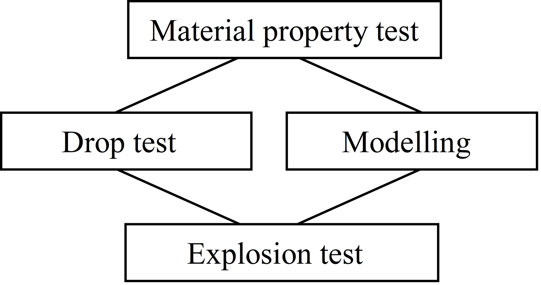
At the outset of this study, the static properties of the alternative insertion materials were measured. A drop test was then conducted in which a simplified metal surrogate (MS) leg [7] was used to test the efficiency of false floors with their various insertion materials. Explicit FEM modelling was carried out as a complimentary study to the drop test. Based on the drop test and FEM modelling results, a practical false-floor configuration was proposed. The proposed false-floor approach was then validated by means of live field trials in which biofidelic frangible surrogate (FS) legs [8] were used. The FS leg, which was developed by the Australian Defence Science and Technology Organisation (DSTO) [8], is a biomechanical analogue human sub-component constructed from materials designed to replicate the bone and soft-tissue properties of an adult human, a feature which is essential for assessment of complex injury processes. Such legs have been used by the DSTO in combat-injury trials for both weapons effectiveness and personnel survivability modelling studies. Having now been fused with results from DRES’ mechanical leg (UK), as well as cadaver (leg) trials results from ARL’s Aberdeen Test Centre (US), this is now an internationally calibrated and validated product. The research flow logic is shown in Figure 1.
Material Static Stress-strain Relationship
The static stress-strain relationship of three insertion materials was determined using an Instron test machine. The candidate materials were:
- 10mm-thick, rib-sectioned rubber sheet;
- 50mm-thick, polystyrene sheet; and
- 40mm-thick, resin-impregnated, paper honeycomb sheet.
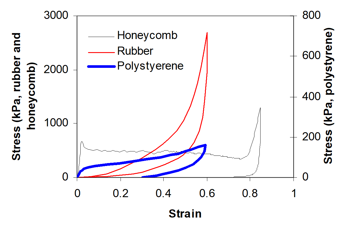
Considering the factors of the material non-homogeneity (rib-section of rubber sheet and honeycomb cells) and buckling stability, a relatively large specimen area of 90-mm square was used. In the tests the Instron crosshead speed was set at 1 mm/min for the rubber specimens, and 5 mm/min for the polystyrene and honeycomb specimens.
Drop Test
The drop experiments were conducted using a vertical-impact machine. The machine consists of a rigid test bed (mounted on vertical guide rods) that is propelled downwards, by both a series of rubber bungee cords and gravity, onto a fixed impact pad in the test. Impact speed is controlled by varying the drop height. The elastomeric impact pads govern the deceleration characteristics of the test bed. Figure 2 shows the drop machine (without showing bungee cords) in which a metal weight has been used to represent the surrogate leg. The metal surrogate (MS) leg was stabilised horizontally by an alignment frame, and vertically by a seat-belt harness. The MS leg consisted of a cylindrical mass above a 30-mm diameter rod with a total weight of 11.5 kg. An accelerometer was fitted on the top of the cylindrical mass, and strain gauges were fitted on alternative sides of the support rod.
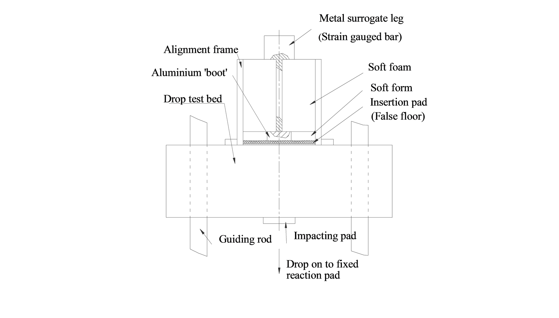
The false-floor was represented by an aluminium sheet, 300-mm square and 6-mm thick. The insertion materials employed were the polystyrene, rubber (two layers) and honeycomb sheets, with area sizes being 300-mm square, 190x150 mm and 150-mm square, respectively.
The deceleration profile of the drop test bed was tuned such that upon impact, it experienced a single impulse deceleration. The deceleration took the form of a half-period sine wave, with an amplitude of 350 g and a duration of 5 ms, which simulates a typically severe impact load in a real-life scenario. In order to avoid rigid impact due to any initial gap in the system, a small pre-load was applied using the seat belt harness.
FEM Modelling
The FEM modelling aspect of this work made use of the Dyna3D software package [9], which is an explicit FEM modelling tool particularly suitable for transient analyses. The MS leg was modelled (Figure 3) as a mass and elastic spring (previous tests and analyses [8] indicated that this one-degree-of-freedom model was adequate) while the false floor was modelled as a non-linear spring.
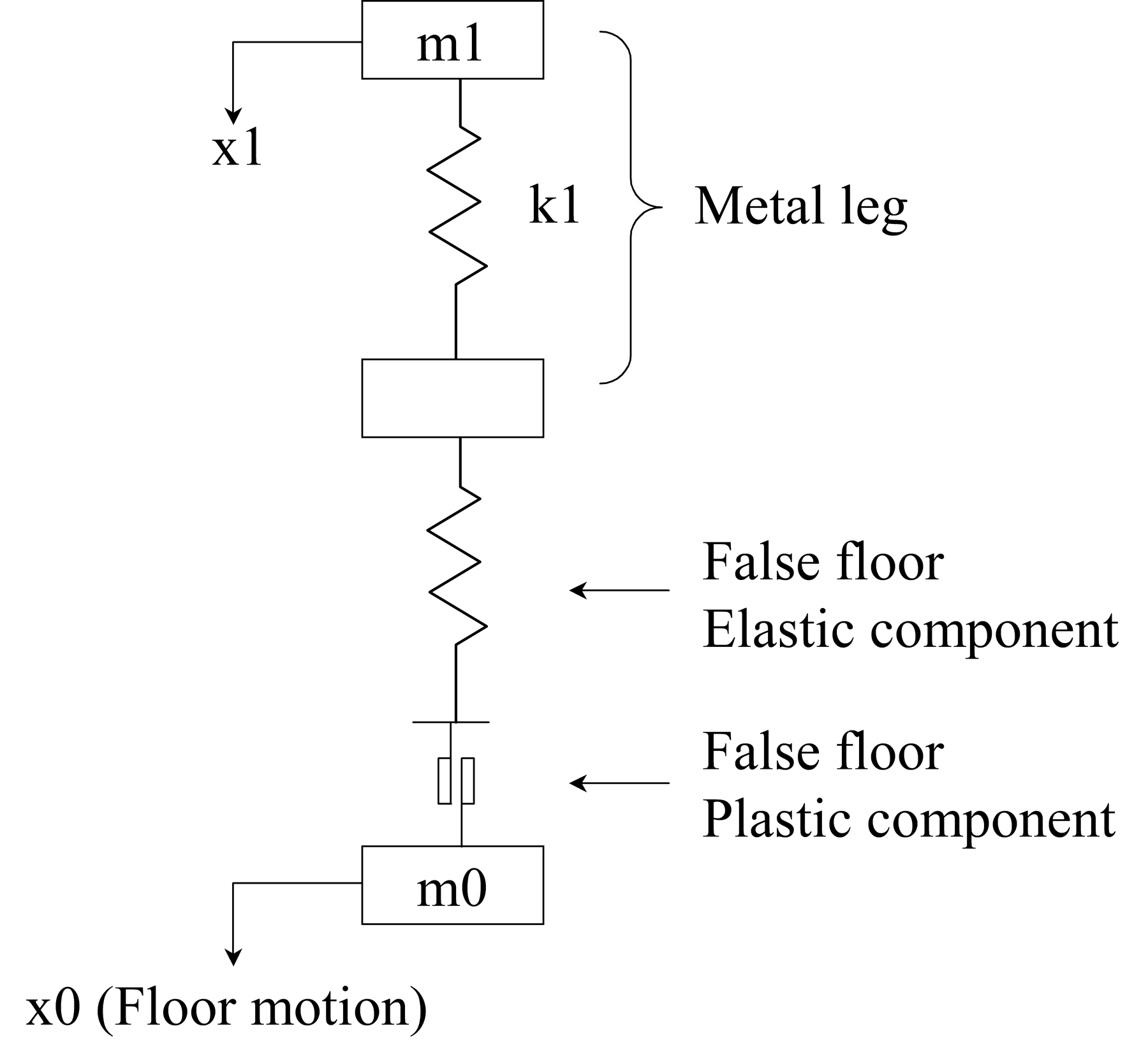
The material form used in Dyna3D for the false-floor was Spring-General-Elastic, which is able to model the behaviour of elastic, non-elastic loading (either strain-hardening or strain-softening) and unloading with hysteresis. The parameters used (Figure 3) are: m0=3 kg, m1=10.55 kg, and k1=3.27x10⁸ N/m. The measured compressive non-elastic properties (Figure 4) were used as the material properties for the false-floor element. In addition the tensile stiffness of this element was assigned with a small value to simulate the contact between the false floor surface and the leg foot. The acceleration profile of the rigid test bed used in the drop test, was specified as the load of the system.
Explosion Test
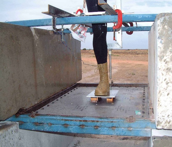
The test set-up is shown in Figure 5. The floor is a 1300x800x6-mm aluminium alloy plate, which was bolted to a steel frame that was in turn clamped between massive concrete blocks as shown. An FS leg was placed on the floor at the centre. A displacement transducer and accelerometer were installed on the floor near the leg to monitor the floor’s vertical motion. Strain gauges were installed on the FSL’s tibia to measure the axial strain and load. Plastic explosive (PE4) charges were buried under 50 mm of dry sand beneath the floor plate. The stand-off distance from soil surface to the floor plate was 600 mm. X-ray and computer tomography (CT) images of the FS leg were taken at the completion of the tests to quantify non-invasively the biomedical outcome.
Results and discussion
Material Static Stress-strain Relationship
The measured static stress-strain curves are shown in Figure 4 above. From these curves, it can be seen that the rubber sheet clearly exhibits non-linear behaviour over the test range, it does not show a clear yield point, and has only a little hysteresis. The polystyrene material has better energy absorbing characteristic as indicated by its much higher hysteresis. However, as the polystyrene yields at a rather low stress level, it may not meet the essential functional requirements of the false-floor insertion material. The honeycomb material has high initial stiffness. Beyond the yield strain, the stress retains a finite value over a strain range of up to 80% then the stress increases rapidly. In the unloading stage there is very little elastic recovery, in other words, the energy absorbing behaviour is excellent. The material also has an appropriate initial strength of about 600 kPa (defined by the yield point). Consequently, a 30x30 cm area will be able to support approximately 54 kN of static load. Furthermore, the ratio between the floor and insertion areas may be reduced to achieve an ideal yielding load. Thus the honeycomb material appears ideal for the false-floor application.
Drop Test and Modelling
The recorded accelerations of the MS leg in the tests are plotted in Figure 6 below. (In Figure 6, and thereafter, the acceleration in the upward direction is considered as positive. This will make the comparison between the drop and explosion test results to be easier). This figure shows that the rubber sheet used does not limit the impact load (since the MS leg is a one-degree-of-freedom system, the acceleration is directly proportional to the compression force). The polystyrene and honeycomb insertions both delayed and reduced the peak acceleration. However, the honeycomb configuration absorbed more energy at the early stage of impaction, and thus the peak acceleration was lower.
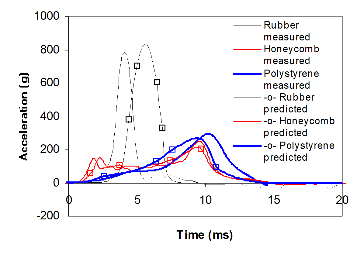
As also shown in Figure 6, the predicted outcome agreed well with the measured results, particularly in the cases of the honeycomb and polystyrene configurations. This indicates that this modelling tool may be used in similar situations with confidence.
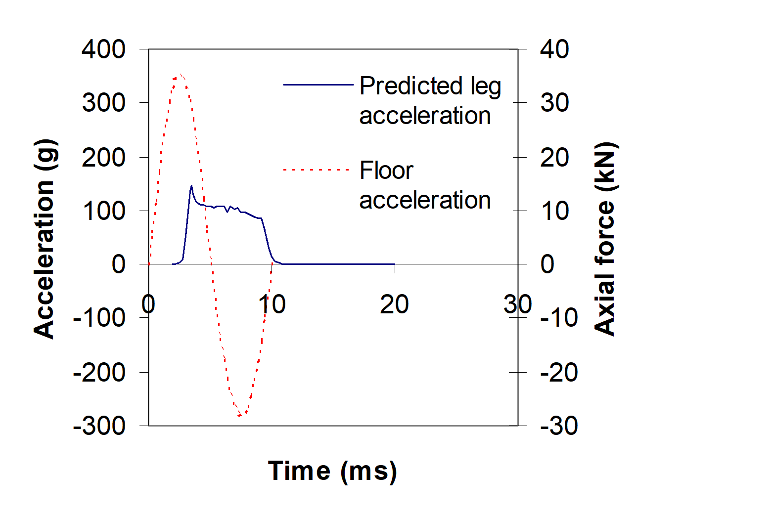
It should be noted that since the speed change of the local vehicle floor is much higher than the average speed change of the vehicle, a high deceleration must follow when the floor acceleration stage is completed (otherwise the local floor would separate from the vehicle). The laboratory drop test may not properly simulate the ‘real-life’ vehicular floor deceleration, hence the laboratory loading used corresponds to a worse-case scenario. On the other hand, the numeric model, verified by the drop test, is able to predict the floor motion more realistically, including both acceleration and deceleration stages. A prediction was made, using the acceleration load as prescribed above, then followed by a deceleration (Figure 7). This deceleration has an amplitude of 280 g and a duration of 5 ms. Application of this load profile resulted in a residual floor upward speed of 3 m/s (estimated average vehicular speed). As shown in Figure 7, the results indicate that the honeycomb false-floor is expected to limit the peak load to about 14 kN, which equals the yield strength multiplied by area of the honeycomb material. The load limit may be further reduced by reducing the area of the honeycomb material. On the other hand the appropriate energy absorbing capacity of the honeycomb material may be achieved by varying the material thickness, which is necessary for avoiding excessive material compression (‘bottom out’) during the impact.
Explosion Test
Two tests were conducted with 100 g of PE4. The first was with the FS leg foot in direct contact with the floor plate, and the second with 100 cm2 of honeycomb false-floor plate (6-kN yield load) under the FS leg. The FS legs survived in both tests.
As shown in Figure 8, the measured peak strain of the tibia in the unprotected leg was 20,000 μ-strain, which is within the upper strength limit of the bone material as determined from static tests. On the other hand, the honeycomb false-floor gave a much lower peak strain value of 6,100 μ-strain.
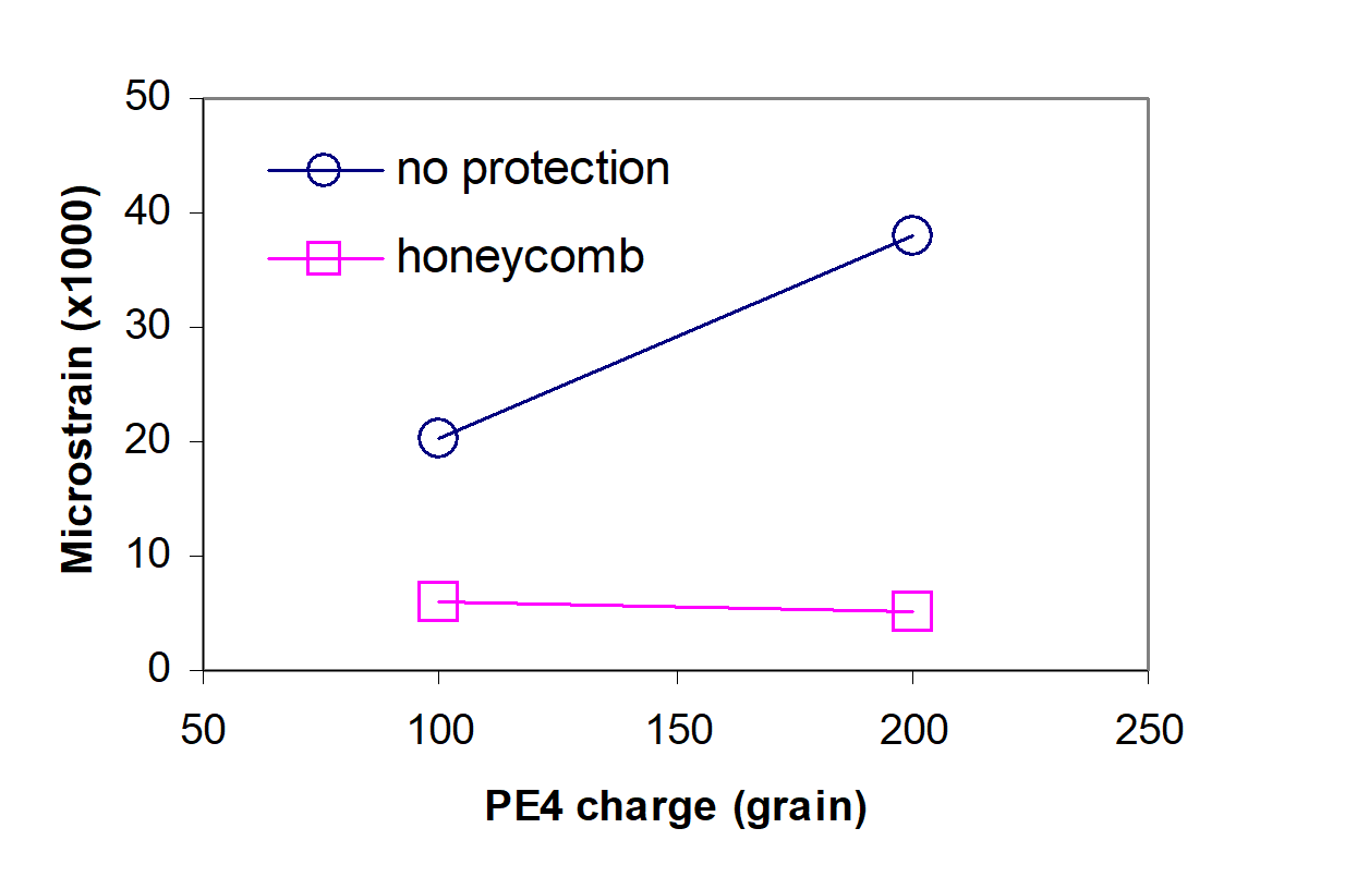
Two tests with 200 g of PE4, and the same configurations were also conducted. Where there was no false-floor countermeasure, the FS leg was fractured at both the ankle joint, and at the lower 1/3rd tibia. However, when the honeycomb false-floor was utilised, the FS leg remained intact, with its peak strain value at a low 5,200 μ-strain (Figure 8). In both of the 200 g PE4 tests, the measured maximum displacement of the floor near the leg was about 40 mm. At the same location, the measured average acceleration was about 1,000 g with a duration of about 2 ms. The data shows that the impact load through the floor was rather severe.
Using the section area of the tibia (where the strain gauge was located), the modulus of the bone and the measured strain values, the axial loads in the two tests with the honeycomb false-floor were estimated to be 7.2 kN and 6.1 kN respectively. In consideration of the 6 kN design load limit as well as the possible non-uniformity of strain in the tibia under test conditions, the correlation is excellent.
Conclusions
- In order to protect occupants in vehicles, AVL countermeasures need to be incorporated into the vehicle design. One such measure that can make a significant safety contribution is novel floor design.
- A false-floor approach has been proven to be an effective method for limiting impact load transmission through the floor, thereby protecting the lower limbs of the occupants. In the case of severe floor impact, an unprotected FS leg was broken at the lower 1/3rd tibia, and the ankle joint, whilst under identical conditions, an FS leg protected by means of a honeycomb false-floor, remained intact.
- Further research and development in the application of a false-floor approach is needed.
Acknowledgements
The authors would like to thank Mr R. Dal Nevo of Crashlab, Road and Traffic Authority, New South Wales for his valuable contributions in the drop test, and Mr D. McQueen, Mr M. Footner, Dr I. Lochert, Mr G. Katselis and other colleagues of the authors at DSTO for their help in the testing.
References
P. Stiff, Taming the Landmine, Galago Publishing, Republic of South Africa, 1986.
A. Hirsh, “Man’s Response to Shock Motions”, Winter Annual Meeting of ASME, Philadelphia, PA, Paper No. 63-WA-283, 17–22 November 1963.
Australian Energy Dissipation Material. Defence Trials Report No 8/435, Service Laboratories and Trials Division, Defence Science and Technology Organisation, Canberra, 1979.
J. Harrigan, S. Reid and C. Peng, “Inertia Effects in Impact Energy Absorbing Materials and Structures”, International Journal of Impact Engineering, Vol. 22, No. 9, 1999.
M. Richards and R. Podob, “Development of an Advanced Energy Absorber”, Proceedings of Annual SAFE Symposium. Survival Flight Equipment Association, Nashville, TN, USA, 1997, pp. 321–327.
E. Wu and W. Jiang, “Axial Crush of Metallic Honeycombs” International Journal Impact Engineering, Vol. 19, No. 5–6, 1997, pp. 439–456.
S. Cimpoeru and R. Woodward, “A Model System for the Analysis of Dynamic Axial Loads on the Lower Leg”, ACAM99, The Second Australasian Congress on Applied Mechanics, IEAust, Canberra, Paper R-043, 10–12 February 1999.
A. Krstic, J. Wang, R. Atkinson, M. Henneberg, D. Netherway, A. Abbott and M. Chehade. “Anti-Personnel Landmine Effects: A Novel Approach”, DSTO technical report (in process). Also published in proceedings of SOMOS Conference, San Antonio Texas, USA, December 2000.
LS-DYNA Version 950, Livermore Software Technology Corporation, USA, 2000.