
Volume 4, Number 2, July 2001
System Integration and Flight Testing of a Laser Designation Pod and Laser-Guided Bombs on the Italian Tornado Interdiction Strike Aircraft
Abstract
Since the beginning of the 90’s, the Italian Air Force Flight Test Centre (CSV-RSV) has been involved in various activities related to laser-guided weapons and infrared laser designation systems for airborne and ground applications. The Thomson Convertible Laser Designation Pod (CLDP) with both TV and IR capabilities have been integrated on the TORNADO Interdiction Strike (IDS) aircraft, together with Laser Guided Bombs (LGBs) PAVEWAY II and III. Ground laser target designators and laser warning receivers have also been tested. Further activities, currently ongoing, include the integration of the CLDP and improved LGBs on the AM-X aircraft. This paper begins with a review of the military requirements and flight test activities carried out on the Italian TORNADO-IDS, followed by a description of the CLDP/LGBs characteristics and performance. It then goes on to present the simulation tools which have been implemented for systems integration and performance/safety analysis with an emphasis on the inherent advantages introduced during development and flight test activities (that is, aerodynamics and safe-separation analysis, preliminary performance estimation, laser hazards determination and laser/ballistic safety assessment, test activities speed-up).
Introduction
The theory of operation of laser guided weapons is simple. The Laser Target Designator (LTD) is an accurate pointing system which provides the laser source and the precision optics and stabilisation required to shine the laser beam accurately on to the target. The LGB detector assembly generates an electric signal when light in received at the wavelength of the laser, consequently the laser light reflecting off of the target is “visible” to the weapon. This provides signals on which the weapon can “home” toward the target by actuation of its aerodynamic control surfaces. Obviously, the pointing accuracy of the laser is important, as any pointing error will degrade the accurate delivery of the weapon.
On the TORNADO-IDS the CLDP is a non-jettisonable store and is carried on the forward section of the aircraft left shoulder pylon. The GBU-16 (PAVEWAY II) LGB is the second generation of LGB and has a MK-83 1000 pound warhead, and the modular electronics and mechanical assemblies designed to provide the weapon with the capability for laser terminal guidance. The GBU-16 is designed for medium- and high-altitude attacks, performed both in level and dive conditions. Theoretically the bomb may be dropped in loft conditions but the associated release envelope is narrowed and the delivery accuracy is degraded.
The GBU-24 (PAVEWAY III) is the third generation of LGB and is specifically designed to enhance low-altitude delivery (hence the name Low Level Laser Guided Bomb—LLLGB). The weapon characteristics also greatly simplify medium- and high-altitude deliveries.
The TORNADO CLDPs main functions are selected by the Weapon System Operator (WSO) whose controls are located in the rear cockpit. The pod Line of Sight (LOS) controls are located both in the front and rear of the cockpit. The system allows both self-designation and co-operative attacks, and can also perform accurate navigation fixes by range finding.
For the CLDP and LGB flight testing a new tailored philosophy was adopted in order to reduce the costs associated with the development process and to obtain the highest possible levels of efficiency. Particularly, instead of carrying out flight trials at the end of the systems integration process, there was a constant involvement of flight test human resources in the various integration design phases, and participation of systems engineers in the flight test planning activities.
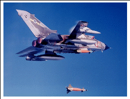
Various simulation tools were implemented during the development and experimental activity and progressively improved as a flight test activity spin-off:
- Store Separation Simulation;
- Aerodynamic Simulation;
- Guided/Unguided Weapon Simulation;
- Masking Analysis and Simulation;
- Aircraft Weapon Aiming Simulation;
- CLDP Performance Simulation; and
- Ballistic and Laser Safety.
Simulation tools were considered essential for correctly planning flight test activities, analysing flight test data, and verifying the validity of the models/algorithms loaded in the operational aircraft software.
In particular, the adopted development/test methodology, which consisted in a continuous interaction between ground test, flight test and simulation, gave a considerable benefit and demonstrated improvements in efficiency (development and test activity speed-up) and optimisation of flight test data gathering. A consequent reduction of costs and time was therefore experienced in the process.
Military Requirements
As a result of the lessons learned in Operation Desert Storm, PAVEWAY II (GBU-16) was integrated on the TORNADO-IDS aircraft, together with the Thomson CLDP, in order to satisfy the initial requirements for an off-the-shelf (low-cost) LGB. The flight test activity was conducted at the Italian Air Force Test Range (Salto di Quirra—Sardinia) and at the Cazaux Test Range in France. During this activity, laser eye-safety issues had to be investigated, and simulation activities were carried out in order to investigate safe-separation aspects, to determine ballistic safety areas and to speed-up the flight test sessions by gradually getting confidence on the LGB/CLDP combination performance. The results of the activity were very satisfactory, allowing a successful employment of PAVEWAY II in the Kosovo conflict.
During the end of the 90’s, further requirements were established by the Air Force for improved CLDP software capability and for a longer range, wider envelope LGB, with high accuracy and hit probability. The chosen LGB was the GBU-24 (PAVEWAY III).
The CLDP improved software was again tested at the Air Force test range, and for these activities a simulation program was developed which allowed the complete assessment of laser eye-safety aspects (that is, determination of laser safety areas and aircraft flight envelope limitations) based on laser hazard statistics and aircraft/pod dynamic calculations. Furthermore, algorithms were developed for determination of the performance of various CLDP/LGB combinations in all weather conditions and in different operational scenarios.
The Operational Requirements for CLDP and LGB integration on the TORNADO-IDS included definition of:
- specific mission requirements,
- functional requirements,
- crew members workload, and
- man-machine interface (MMI).
Accomplishment of these requirements needed to be verified in the initial development phases as well as during the various flight test campaigns carried out. Particularly, in order to fulfil the military requirements, the following activities were carried out:
- systems selection,
- aircraft aeromechanic integration,
- hardware integration, and
- software integration.
The following criteria were adopted for the selection of the systems (LGB and CLDP) to be integrated with the TORNADO-IDS aircraft:
- proven operational capability;
- full compliance with the basic operational requirements;
- low risk during the development phase;
- commonality with other sub-systems and TORNADO-IDS suspension system;
- state-of-the-art technology in order to guarantee longer operational life; and
- system upgrade potentials for future applications.
As a result of this philosophy, the selected systems (CLDP and GBU-16/GBU-24 LGBs) only required minor design changes in order to interface with the TORNADO-IDS aircraft:
- MIL BUS 1553B wiring for CLDP;
- electrical/Mechanical adapter for coupling CLDP with TORNADO suspension system;
- CLDP dedicated Control Panel;
- video signal distributor and wiring to TV through CLDP control panel;
- CLDP video signals adaptation to TV video standard; and
- specific bomb dressing design.
Systems Description
CLDP Description
The Convertible laser Designation Pod (CLDP) is a system designed to provide the aircraft with day and night laser designation capability, for co-operative and self-designation type attacks using laser-guided weapons. The pod is equipped with an internal designation laser operating at 1.064 µm (non-eyesafe region of the spectrum) and may be configured for day-time operation by using a television camera (TV) or for day/night operation by using a thermal camera (TC). The TV configuration may also provide daytime advantages in high humidity conditions. In its subsidiary role, the CLDP can also act as a sensor for navigation fixing including height fixing.
Both CLDP configurations consist primarily of two sections (Figure 2)—an interchangeable front section containing a TV sensor head or TC sensor head, and a common body containing a centre section and rear cooling unit.

In conjunction with the main computer (MC), real-time video with CLDP symbology is displayed on the aircraft TV navigator’s display, and the CLDP related symbology is displayed on the pilot’s Head-Up Display (HUD).
An electrical adapter installed on the back of the centre section provides the electrical interface between the CLDP and the aircraft. The adapter interfaces with the MC via the Missile Control Unit (MCU), using a MIL-STD-1553B data bus.
GBU-16 (PAVEWAY Ii) Description
The GBU-16 (PAVEWAY II) laser Guided Bomb consists of a forward Computer Control Group (CCG) which includes the control canards and an aft wing assembly, attached to the MK-83 body (Figure 3).
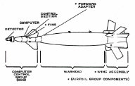
The Detector Unit Housing (DUH) is mounted on the front section of the CCG and is free to “gimbal” (move laterally) in any direction, and is aerodynamically stabilised by the ringtail moulded into the rear of the housing.
To a first approximation the detector is aligned with the velocity vector of the weapon. The detector senses the laser energy reflected from an illuminated target. The detector output is amplified and converted into commands that are transmitted to the forward control canards.
GBU-16 guidance is provided by a system commonly referred to as “Bang-Bang” control. When the computer senses a position error, the control canards are driven to the limit of their travel by high-pressure gas, regardless of the magnitude of the error. Therefore, the control canards are either at the trail position or full deflection during guidance.
The GBU-16 guidance system attempts to fly a straight-line trajectory from its present location to the illuminated target. At acquisition, the computer section of the guidance unit recognises the angular difference between its flight path (velocity vector) and the LOS from its present position to the illuminated target (guidance error angle). By adjusting the GBU-16 flight path to reduce the magnitude of this error, the weapon can be guided to the illuminated target.
GBU-24 (PAVEWAY Iii) Description
The GBU-24 (PAVEWAY III) consists of a nose-mounted guidance unit and an aft wing assembly which can be mounted on various classes of warheads. The Italian Air Force selected two 2000 pound bombs, namely the MK-84 (complete assembly GBU-24(V)1) and BLU-109 (complete assembly BGU-24(V)2) high-penetration warhead.
As in the case of GBU-16, GBU-24 is loaded, released, or jettisoned using the same ground equipment and aircraft systems used for employing conventional, unguided warheads. Operation is independent of the aircraft except for normal suspension and release functions. No electrical interface or aircraft modification is necessary and these weapons may be carried (upon certification) by any aircraft capable of carrying the parent unguided warheads.
In comparison to GBU-16, the GBU-24 is a proportional guidance LGB, which continuously tracks the maximum of the target-reflected laser energy and actuates the aerodynamic surfaces in proportion to the measured error. The bomb has four different operational modes, selectable on the ground, prior to the mission, depending on the target characteristics (that is, hard or soft) and the desired bomb impact angle. For each mode of operation, the GBU-24 computer unit automatically selects a suitable flight profile (from a number of pre-set profile types) depending on the release conditions.
Man-Machine Interface
The various CLDP functions (automatic or selectable by the crew man machine interface—Figure 4) are described in the following sections.
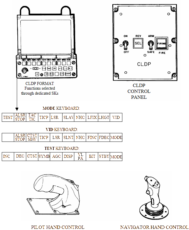
System Initialisation. The pod is switched on via the CLDP Control Panel. The system executes a start-up sequence, checking CLDP internal equipment status. At the end of this sequence the pod enters the stand-by mode.
CLDP System Status Check. The system continuously checks the integrity of the CLDP-aircraft communication, advising the crew of any failure occurrences. If an internal equipment failure is detected by the system, a specific warning is shown on the TV WSO display. Further advice of pod internal sub-system failure is also given to the WSO by means of a dedicated TV CLDP format that can be recalled through a display “soft key”.
Slave Modes. The CLDP LOS pointing is controlled through direction cosines coming from the aircraft main computer. Furthermore, pointing can be adjusted manually using the Navigator or Pilot Hand Control. The following sub-modes are available:
Slave-Slave. The LOS is directed at the target or a fixed point provided that the system is in Fixing or Attack mode. In this mode the LOS pointing is fixed to the target virtual position (LOS ground stabilisation).
Slave-Ground Stabilised. The LOS position can be adjusted via the Navigator Hand Control (NHC) inputs. In this mode the LOS is ground stabilised to the target position taking into account the NHC demands.
Slave-Cage. The LOS points straight ahead in Azimuth and 4 deg down in Elevation.
Slave-Manual. The LOS direction can be controlled via NHC inputs. Starting in a Slave-Cage position (system in navigation mode), LOS pointing can be adjusted via NHC (see also Slave-Ground Stabilised mode). In this mode LOS is not ground stabilised (no target/fixed-point is recognised by the MC).
Track Modes. The pod enters the Track mode from Slave mode on selection by the WSO. With the Tracking mode selected, the pod does not consider the MC inputs in terms of LOS direction cosines but it maintains the LOS overlapped to the target by using one of the two available sub-modes:
Tracking by Area Correlation (TAC). The CLDP performs a digital store of the whole video image which is then superimposed onto the actual live image. The correlation between the two scanned images generates commands to move the LOS consequently. However, the LOS can be manually oriented provided that NHC is selected for CLDP use.
Tracking by Image Contrast (TIC). The CLDP performs a digital scan of the video image looking for an area of high contrast compared to the background. The CLDP then will correct the LOS position over that area, focused to the video centred image. If the position is manually adjusted via NHC, then this function is disabled and the TAC mode is automatically re-selected.
Masking. The CLDP LOS pointing is limited by aircraft masking effects (that is obscuration of the CLDP line-of-sight due to impingement of the aircraft body). The CLDP automatically prevents the laser from firing on the aircraft structure and external stores. Together with the aircraft profile (including stores), the masking function also takes o into account the CLDP Blind Cone (CLDP rear). A pre-masking function is also available to warn the aircrew of the mask limit proximity.
Computed Rate Track (CRT). The CRT function is automatically selected whenever Tracking mode loses “good track” or at the occurrence of a mask impingement. In CRT mode the LOS is aimed to the target by the CLDP computer using the aircraft velocity, attitude and Slant Range to target information provided by the MC.
Pod/Aircraft (P/A) Harmonisation. The Pod/Aircraft Harmonisation procedure must be performed every time the pod is installed on an aircraft. The procedure corrects the misalignment between the CLDP and the aircraft axes. Providing that the pod is in Track mode, this function can be performed through WSO and Pilot cooperation (Pilot method) or by the WSO only (Navigator method). During P/A Harmonisation procedure, the misalignment in Z and Y rotation axes (vertical and transverse axis) is calculated by the system and stored as delta-pitch and delta-yaw angles to be added to the Azimuth and Elevation LOS pointing.
Video/Laser (V/L) Boresight. The V/L Boresight function is used to check the laser efficiency and to correct any Laser/Optical axis misalignment. This function is required to be executed before attack/fixing.
Reversionary. The Reversionary mode is automatically selected if the Weapon or Avionics Bus fails, the Weapon Bus is shut-down as result of MC failure or Re-cycle, or the MCU fails. When in Reversionary mode the pod is still capable of tracking and illuminating the target.
CLDP Target/Navigation Fixing. The CLDP can be used as a sensor for target/navigation fixing purposes, in the following modes:
Plan Fixing mode (no laser operation). The CLDP LOS angular position and selected height sensor data are used to calculate the aircraft position with respect to a target/fixed-point;
Three Dimensional Fixing mode (laser operation). Laser Range and LOS angular position are used to calculate the aircraft position with respect to the target/fixed-point.
Designation Attacks. The system allows for:
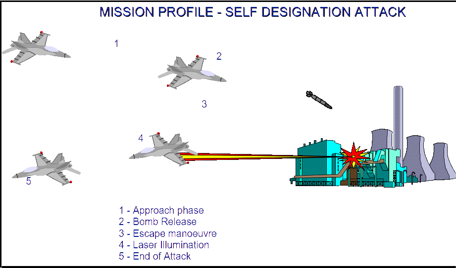
Self Designation Attacks, in which the aircraft acts as the illuminator for its own carried LGBs. The following bomb attack profiles can be performed during self-designation attacks: GBU-16: Dive, Level, Loft; andGBU-24: Dive, Level. An example of a typical GBU-16 self-designation mission profile and laser Illumination Logic is shown in Figure 5.
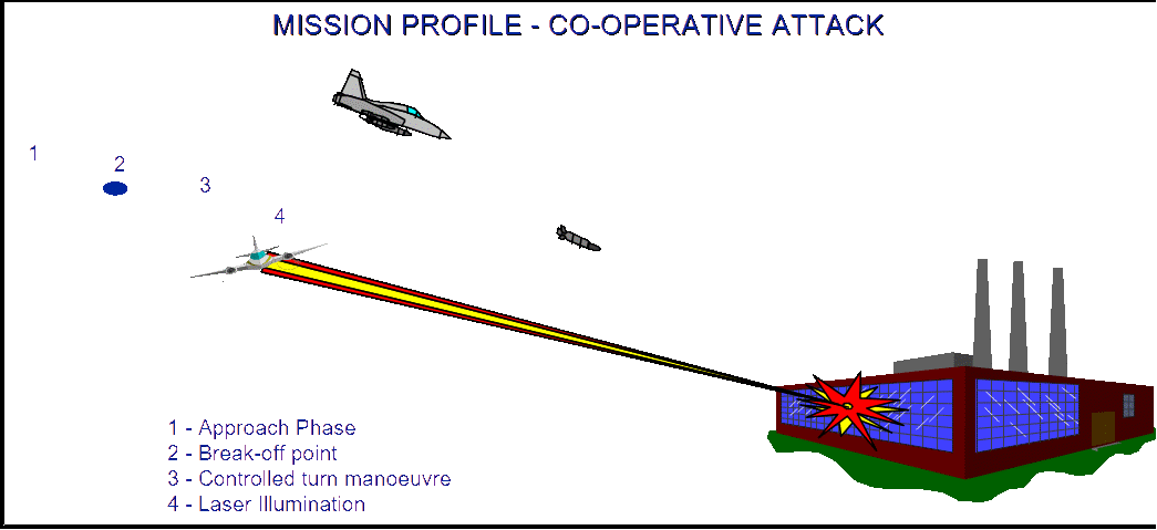
Co-operative Designation Attacks. In these attacks the aircraft acts as the illuminator for partner(s) aircraft. Co-operative profiles can be chosen between: NSTR (No Steering), in which the aircraft is directed to over-fly the target; and STR (Steering), in which the aircraft is flown to pass at a tangent to the Lethal Range Circle. The laser can be operated by a pre-planned counter (Real Time or Count Down) or manually. An example of a typical Co-operative attack mission profile is shown in Figure 6. Steering laws require that the attack is initiated, respecting the aircraft to target minimum distance (break-off point not yet reached) and Track angle error within the operational limits, as shown in Figure 7. If one or both of these limits are exceeded, the aircraft will not properly perform the expected turn or will not acquire the planned heading change.
Flight Test Philosophy
Flight test activity is the most important data gathering exercise to validate the system performance and reliability. However, the advantages offered by flight trials are paid in terms of a dramatic increase of development costs. In the case of the CLDP and LGB flight testing, a new tailored philosophy was adopted in order to reduce the costs associated with the development process and obtain the highest possible level of efficiency. Particularly, instead of carrying out flight trials at the end of the systems integration process, there was a constant involvement of flight test human resources in the various integration design phases, and participation of system engineers in the flight test planning activities.
A ‘Tornado Team’ was created in which participation of specialists from different disciplines was assured:
- flight test engineers (FTE’s);
- system engineers (SYE’s);
- software engineers (SWE’s); and
- experimental test pilots (ETP’s).
Their participation allowed a continuous interaction throughout the development processes and a consequent definition of a ‘balanced’ test matrix.
As a result, test items allocated to flight trials were sensibly reduced due to a sharper and more careful selection of non-redundant and significant test items, aimed at calibrating the simulation models to allow a more accurate prediction of physical phenomenon and possible operational deviations.
In this perspective, flight trials were not considered as the final step of the system operability/reliability verification process, but became an active part of the development process itself. The adoption of this methodology conferred considerable benefits and introduced significant improvements in efficiency and optimisation of data gathering. A consequent reduction of costs and time was therefore experienced in the process.
Test Requirements and Methods
Once the electrical/mechanical compatibility of the sub-systems with the aircraft was assured, the following areas of testing were identified:
- flight mechanics (handling/vibration);
- store separation (LGB’s);
- software development; and
- avionics and sub-system testing.
The test requirements, mathematical models and analysis tools were used to define the aircraft in-flight data acquisition, telemetry systems and the related list of parameters that would be recorded during tests.
A limited number of parameters were available from transducers fitted to the aircraft structure, but the avionics system provided the main source of flight data (MC digital stream, avionics and weapon buses, serial lines tapping, videos and cameras).
Flight Mechanics Testing
Handling flights were dedicated to investigate aircraft stability and control flight quality. Typical manoeuvres were performed at selected flight conditions to validate the predictive mathematical models used. In flight aircraft behaviour was ascertained to be very similar to that predicted, and hence allowed the theoretical analysis to be extended to encompass the whole flight.
Vibration flight activity was required to measure the actual vibration levels induced on the CLDP and the adaptor under the selected flight conditions and aircraft external stores configurations. An instrumented dummy CLDP, with embodied transducers and recording system, was supplied by Thomson. Vibration transducers were also distributed along the adaptor structure and linked with the CLDP embodied recording system. CLDP data and aircraft flight parameters were analysed to identify the vibration levels.
Store Separation Testing
The Store Separation Testing activity for integration of the LGB’s on the TORNADO-IDS aircraft was carried out in three different phases:
- pre-flight analysis;
- flight trials; and
- post-flight analysis.
Pre-flight analysis. A series of ground tests and intensive use of mathematical modelling were used to ascertain the likely separation characteristics. The following critical areas were identified:
- aerodynamic interference on the LGB separation in the presence of the CLDP (mathematical models);
- LGB dressing/mechanical interference with the aircraft suspension system (pit-drop trials); and
- unexpected LGB pitch attitude during initial separation phase (mathematical models, pit-drop trials).
These tests led to the following solutions:
- CLDP repositioning;
- modification to the LGB standard dressing; and
- ejection throttle setting optimisation.
A second cycle of pre-flight analysis was then carried out to further refine the simulation models and, on the basis of the new predictions, to identify the relevant areas of flight testing.
Flight Trials. According to the test philosophy principles, the store separation flight activity would be used to acquire information about the bomb ballistic characteristics and hence help to identify solutions for the development of the weapon sub-system software. LGB jettison and releases at the selected flight conditions were required in order to:
- confirm the store separation predicted by the mathematical models;
- verify any possible mechanical interference between ‘dressing’ and the TORNADO suspension system;
- verify aerodynamic influence on unguided store trajectory;
- acquire data for optimising ballistic constants; and
- enable optimisation of the attack profiles during simulated CLDP designation.
Post-flight analysis. The results of the flight activity were analysed and compared with the mathematical predictions. The simulation models were then further refined with the aim of extending the jettison and release flight envelope up to the whole required operational envelope.
Software Development and Testing
The development of the avionics software was done in three phases: software definition; software coding; and software testing.
Basic functional requirements were used as a baseline for the software definition. During this phase the following aspects were considered:
- avionics equipment involved (Displays and Controls, Main Computer, Missile Control Unit, and so on.);
- upgrading of existing software modules (Weapon Aiming, Navigation, and so on.);
- implementation of new calculation processes to interact with CLDP functions (LOS control, masking, laser firing logic, and so on); and
- data collected during store separation flight activity and experiences gained using simulation models.
The result of this study was the release of the Software Requirement Specification (SRS). Based on the SRS, the software coding process was initiated. In parallel with this the Software testing was scheduled as follows:
Stage A testing. The software routines were verified as stand alone routines using mathematical models to stimulate the functions.
Stage B testing. The algorithms were then combined and tested with single or groups of avionics equipment (real or simulated). Mathematical models were used to stimulate software for interaction with equipment firmware to check the compatibility and reaction of the involved sub-systems.
Stage C testing. Fully representative rigs of the TORNADO avionics system were used to evaluate the performance and reliability of the software in closed loop testing. The software confidence level ascertained during this Stage C testing lead to authorisation for flight testing.
Stage D testing. Flight test activity was dedicated to verifying the software reliability and operational effectiveness, and to define operational limitations in using the weapon sub-systems.
Avionics and Sub-System Testing
Flight test activity was required in order to:
- verify the software integrity, especially in those critical areas where ground test rigs and simulation testing were not the appropriate vehicles;
- evaluate sub-system operability in a real environment;
- suggest further development areas, or optimisations, of existing functions to improve reliability; and
- assess the man machine interface and workload.
During this initial flight activity, the following critical areas were identified:
- the target illumination phase was not optimised at certain attack profiles due to the rapid consumption of bomb kinetic energy during its guided trajectory;
- system operational limitations became apparent due to the very conservative masking profile adopted;
- optimisation of some CLDP control functions;
- deviations were found in bomb ballistic constants;
- masking caption delays;
- LOS control laws;
- LOS stabilisation;
- interaction between Auto, Manual and reversionary laser firing commands;
- safety during laser operations; and
- Co-operative attack limitations.
This led to the following solutions being implemented:
- the target illumination phase was made common for all available attack profiles and release conditions;
- SW was used to induced automatic target illumination according to the bomb real time of flight;
- introduction of dynamic pre-masking and masking profiles according to the aircraft external stores configuration;
- CLDP internal SW modification to cure functional inconsistencies;
- new SW requirements and SW corrections;
- masking routines transferred from the MC to the MCU;
- the pitch/roll Line of Sight rotation was limited during the pod-aircraft axis harmonisation process;
- a local aircraft masking profile geometry was introduced for the reversionary mode; and
- a control safe interaction was implemented between automatic, manual and reversionary laser firing.
Once the sub-system was successfully integrated, a final demonstration, including weapon delivery, was performed in France to evaluate the whole system effectiveness.
Simulation
The simulation tools used during the development and experimental activity, and progressively improved as a flight test activity spin-off, included the following:
- Store Separation Simulation;
- Aerodynamic Simulation;
- Unguided Weapon Ballistics;
- Masking Analysis and Simulation;
- Aircraft Weapon Aiming Simulation;
- Guided Weapon Simulation;
- CLDP Performance Simulation; and
- Ballistic and Laser Safety.
A description of the various tools is given in the following paragraphs.
Store Separation Simulation
The analysis of store separation trajectories, finalised to the definition of the safe release envelope, is one of the most important tasks to carry out, in the aerodynamic design area, for integration of external stores on a combat aircraft. New simulation and analysis tools were adopted for LGB’s integration, which introduced significant improvement.
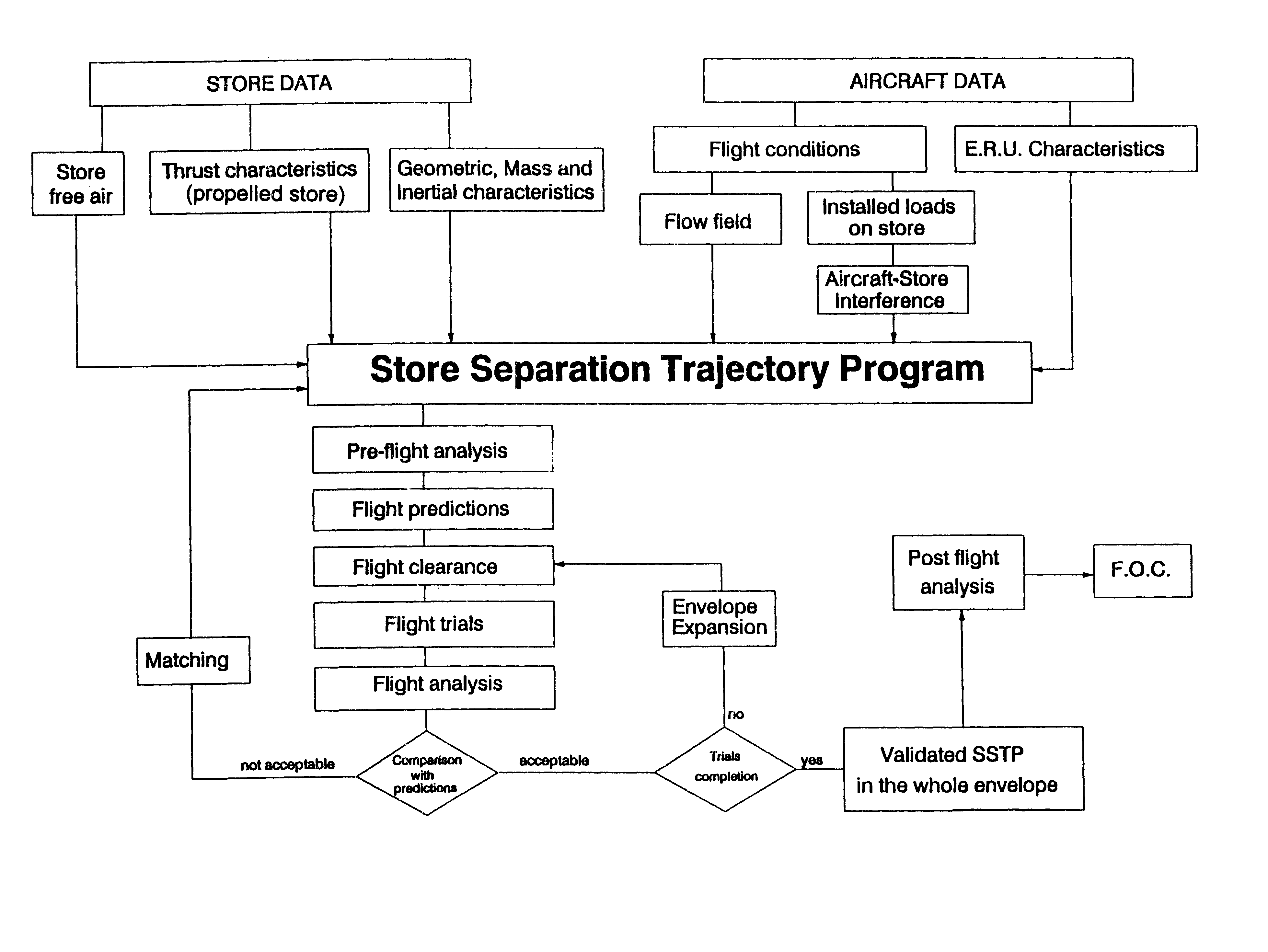
The Store Separation Trajectory Program (SSTP) required a fixed aerodynamic input data set (that is, aircraft flow field, store free-air coefficients and installed loads), making its application very fast and cheap. Comparison with results over many flight test cases, demonstrated its reliability for most stores and release conditions investigated. Nevertheless, for those cases where the flow regimes were characterised by non-linear phenomena and when the store trajectory could be potentially critical, a more accurate method was applied.
This new technique was based on the application of 3D Euler code to evaluate and update the airloads on the separating store at different steps along the initial part of its trajectory.
Figure 8 shows the complete flow diagram of the activities performed to achieve the final operational clearance as far as the store safe separation is concerned.
As shown in the flow diagram, the store trajectory calculation is influenced by the following parameters:
- aircraft flight conditions;
- store mass and inertia characteristics;
- store aerodynamic coefficients (free air);
- aircraft store aerodynamic interference (with loads installed);
- aircraft flow field;
- Ejector Release Unit (ERU) performance; and
- store physical constraints.
Among the above mentioned parameters, making up the mathematical model data set, the aerodynamic data are those having the most influence on store separation behaviour and thus demand the greater effort for their determination.
Aerodynamic Simulation
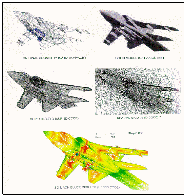
To support the application of CFD codes in the aerodynamic calculations process, a new procedure was developed based on the integration between the CAD-CATIA system and CFD codes, which starting from an initial geometry, leads to the complete analysis of CFD results. This sequence of operation allows for quick and reliable aerodynamic calculations. Figure 9 is an example of the steps required in this process and is described below:
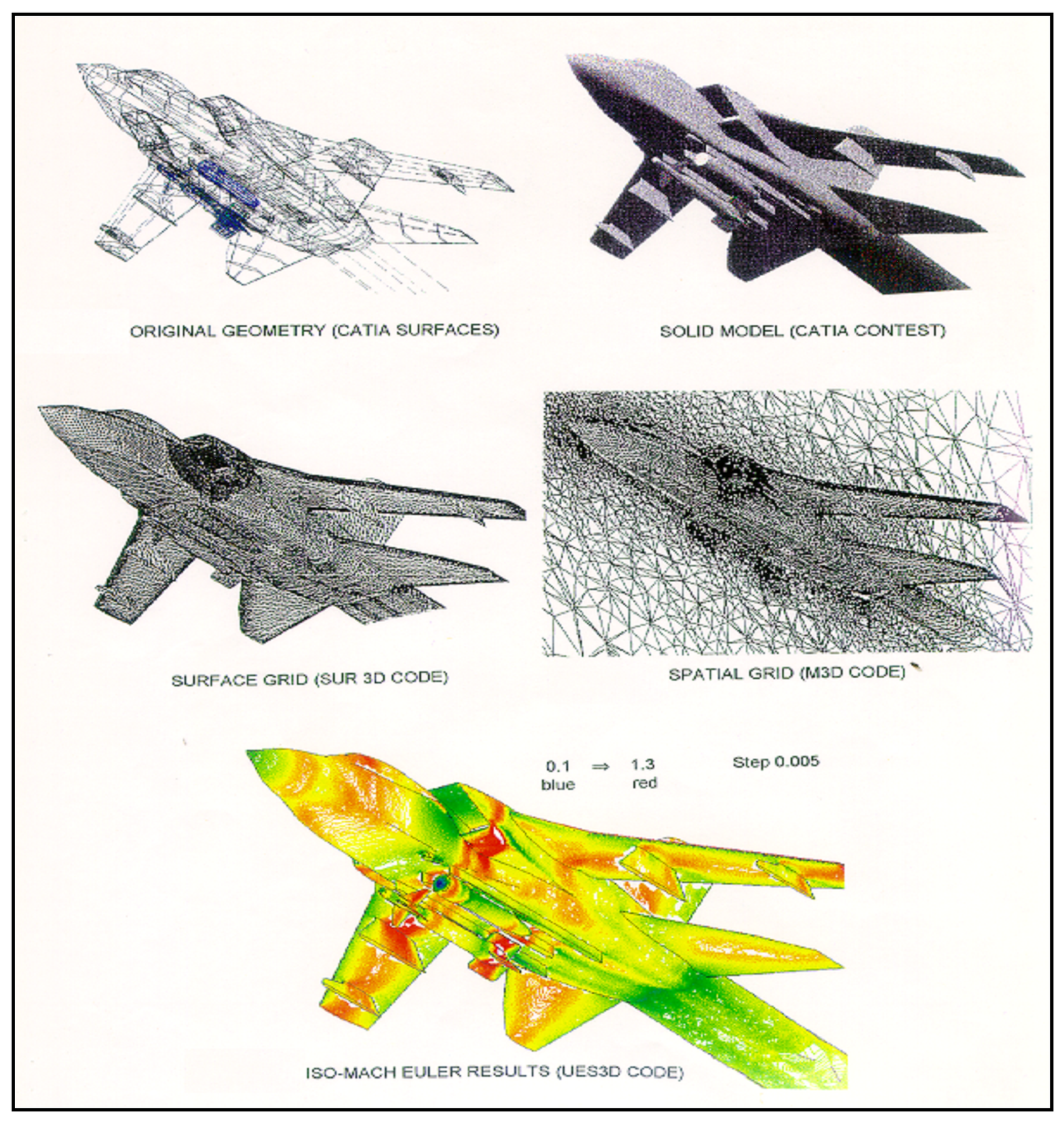
- definition of a conceptual model (from the master geometry data base or other already assessed geometry);
- building up in CAD-CATIA environment of a derived geometry model (by translating a series of points in polynomial entities) congruent to that defined in the previous step;
- possible simplification of the geometry depending on the specific aircraft area to be analysed; and
- transfer of the geometrical data (polynomial coefficients) from CATIA to the input files of CFD codes with the appropriate format.
Furthermore, a 3D Euler flow solver was developed named UES3D. The aim of this code was to find the flow field stationary solution of a three dimensional compressible inviscid fluid by using a pseudo-unstationary method in time and spatial finite volume method on unstructured tethrahedral meshes.
During application of the 3D Euler code the following steps are performed:
- generation of surface and spatial grids to produce the flow field to be used by the analysis code;
- numerical results from Euler-equation solutions (UES3D code) and analysis of these results;
- optimisation of the model on the basis of the result analysis and consequent verification with numerical code; and
- final assessment and loading of the new model in the master geometry database.
The above procedure was adopted in the whole aero-design process, for external stores integration on the aircraft. Particularly, it permitted analysis with strongly representative models (that is, mathematical models from the assessed geometry), and allowed for quick and accurate optimisation of the geometrical model utilised for the aero-analysis.
The optimised geometry could be easily re-inputted in to the master geometry database. Furthermore, the described methodology could be also applied to the aero-analysis required for trajectory computations.
Unguided Weapon Ballistics
The BAL_1 simulation program was developed by in order to compute unguided ballistics tables for any type of bomb released by any type of aircraft, and to define the attack release conditions.
The output ballistics tables consisted of the following parameters:
- bomb range;
- bomb time of flight;
- bomb impact angle;
- bomb impact velocity; and
- bomb depression angle relative to the aircraft at time of release.
The input parameters required were: the Equivalent Ejection Velocity (EEV); drag area; bomb weight; release conditions; and atmospheric conditions.
Masking Analysis and Simulation
Analysis was required in order to fully characterise the masking phenomenon and obtain the related mathematical model to be used by the aircraft MC for CLDP laser firing inhibition during impingement.
The masking model was obtained through a computer CAD simulation that consisted in defining the aircraft shape with different external stores configurations. As a result of the analysis/simulation, the masking function logic was fully defined (Figure 10).
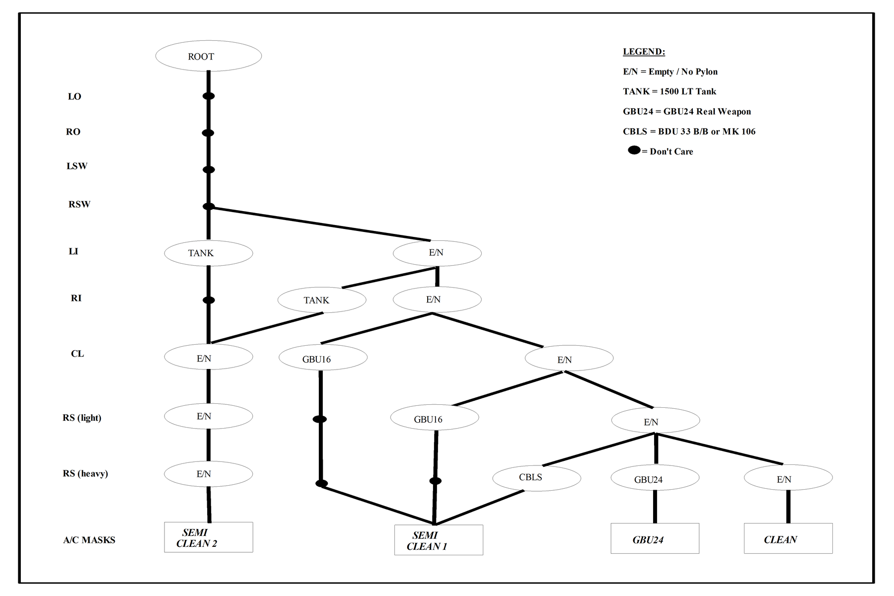
Particularly, the masking function was conceived in order to manage the basic real GBU-16 and GBU-24 Stores Configurations (“worst case” masking profile) and their derived sub-configurations (that is, semi-clean and clean).
Weapon/Aiming (W/a) Simulation
For Weapon Aiming assessment purposes, two simulation programs, named TOR_TRA and TOR_BAL were developed. The TOR_TRA program used the same models adopted by the TORNADO Main Computer (MC) for execution of loft attacks. Therefore, the program was able to work out the aircraft flight conditions during simulated loft attacks. The output of the TOR_TRA program was the following:
- aircraft position relative to the target at the MC commanded “pull-up”;
- the aircraft trajectory deriving by a correct pilot “release cue” (HUD indication) manoeuvring; and
- release conditions (aircraft position and velocity vectors).
In order to carry out its calculations, the TOR_TRA program required the inputs: bomb type; and aircraft loft run-in conditions (velocity and altitude).
Furthermore, it was possible to simulate unintentional pilot error (delay and/or drifts) during execution of the MC required manoeuvre.
Since the TORNADO MC uses simplified, instead of rigorous, ballistics models to calculate in real-time the bomb time of flight and the bomb range, the TOR_BAL program was developed in order to reproduce the same (simplified) models. This program required as input data, the bomb type, the type of attack (that is, high-loft, low-loft, level or dive), the aircraft release conditions and the local wind velocity vector.
The simplified MC ballistics model (and the TOR_BAL program) uses, for each bomb and type of attack, a specific set of ballistic constants. In order to compute these constants for integrating new bombs in the aircraft, a dedicated program, named TOR_COST, was developed.
If a new bomb can be regarded, as far as W/A integration is concerned, as an unguided bomb, then TOR_TRA, TOR_BAL and TOR_COST form a set of programs able to carry out the full W/A integration task.
On the other hand when the released bomb has complex pre-defined flight profiles (as in the case of GBU-24), the W/A integration task must be carried out taking into account these bomb peculiarities.
Therefore, dedicated W/A simulation algorithms must be developed. In the case of GBU-24, two software modules were developed to carry out the following specific sub-tasks:
- a module that selects the appropriate set of envelope constants depending on aircraft flight/release conditions; and
- a second module, based on neural network algorithms, that calculates the maximum and minimum distances of the aircraft to the target (that is, release range envelope) for a successful bomb release.
Guided Weapon Simulation
The program GBU16_TG, released by Raytheon (formerly Texas Instruments), was used during the test activity. The program is capable of computing the guided GBU-16 weapon trajectory, taking into account:
- ground speed;
- aircraft-target distance;
- release altitude/angle;
- attack direction;
- target velocity;
- spot laser position;
- lasing time;
- laser energy; and
- target reflectivity.
The program outputs are:
- bomb flight conditions where the target enters into the seeker field of view;
- bomb flight conditions when the laser starts to fire;
- bomb flight conditions where the bomb starts the guided trajectory;
- bomb flight conditions along the guided trajectory;
- impact point with respect the spot laser; and
- bomb time of flight.
Raytheon developed a similar program for the GBU-24 guided weapon trajectories generation. Unfortunately this program is currently not releasable outside the US. Nevertheless, the results of some pre-defined scenarios were made available for bomb integration activities.
CLDP Performance Simulation
Since the beginning of the experimental activities, it appeared essential to optimise test missions to take into account the tactics of employment of the laser guided weapons in operational scenarios and to verify the performance of the system in a realistic environment. Therefore, a study was conducted in order to define a method for predicting/simulating the performance of the laser system under different operational and environmental conditions. A simplified atmospheric laser beam propagation model was implemented taking into account both absorption and scattering effects, in different weather conditions (visibility, humidity, and so on.). The number of parameters in the model was reduced as much as possible, in order to make the model manageable at an operational level.
The model for dry-air conditions was derived from the studies and experiments conducted by Elder and Strong [1] and Langer [2] on infrared laser propagation at various wavelengths, while for rain propagation the basic model was integrated with the equations developed by Middleton [3]. A diffuse-specular reflection model was adopted and different geometric conditions taken into account, in order to evaluate the CLDP performance in realistic operational scenarios.
A detailed discussion of the various algorithms used in the simulation is given at [4]. The fundamental models used for performance calculation are the following:
Laser Range Equation. A convenient form of the “Laser Range Equation” (suitable for CLDP performance calculations) was used, given a circular aperture and assuming an extended target (that is, a target larger than the beam spot). This equation established a relationship between all the scenario parameters (that is, geometry, propagation, reflection, systems characteristics).
Atmospheric Propagation Model. A laser propagation model, using the Elder-Strong and Langer propagation equations for dry-air conditions, referred to the cases of practical interest, was used. These equations allowed calculation of the atmospheric propagation factor as a function of visibility and absolute humidity in the transmitting/receiving paths. Furthermore, for rain conditions, together with the Elder equations the Middleton model was used, giving the atmospheric propagation factor as a function of the absolute humidity and of the scattering coefficient with rain (which is a function of the rainfall-rate and the dimension of the rain drops).
Geometric Model. The geometric model included technical assumption about the LGB’s guidance characteristics and considerations related with the geometry of self-designation and co-operative attacks performed with the CLDP and the LGB’s.
Reflection Model. For initial performance calculation purposes, the target surface was assumed as a perfect diffuser, scattering incident light equally in all directions. For such “ideal” surfaces, the intensity of the diffuse reflected light is given by Lambert’s law. Subsequently, a more realistic reflection model was used (that is, an empirical diffuse-specular reflection model) with the purpose of identifying optimal bomb-aircraft relative directions for performing successful LGB attacks.
Ballistic Safety Areas
In order to safely carry out flight test activities involving actual bomb drops, it is essential to define the area where the bomb, released from a aircraft with a certain flight profile, could impact the ground, including ricochets (this is called the Ballistic Safety Trace).
A software package was developed capable of producing these Safety Traces. This program was able to manage “dive”, “level” and “loft” attacks with any input entry conditions, type of bomb and error vector. The program output was the Safety Trace border on the ground, obtained by taking into account the worst case simulated impacts. In the program, each impact was calculated by considering the aircraft trajectory, the bomb release conditions, the weapon trajectory and the probable ricochets.
This model was further developed to include the associated probability on the safety trace by the interpretation and processing of the data collected in previous flight trials. This method permitted a progressive refinement of the simulation tool by using actual flight test data.
Adoption of the simulation tool described allowed a thorough investigation of the “unguided” LGB safety aspects. Furthermore, a dedicated tool was developed for the “guided” weapon case, taking into account the worst case conditions of the LGB manoeuvring capability, CLDP lasing time and bomb energy balance.
Laser Safety Areas
Since the CLDP system operates at a wavelength of 1.064 µm (non-eyesafe region of the spectrum), the laser safety aspects were also investigated, in order to define optimal strategies for training/test missions. Particularly, laser safety standards [5-9] were critically analysed in the light of the operational issues related with the use of laser systems. This led to the detailing of the procedures that were to be adopted at the test ranges for laser systems training and evaluation. Finally a computer simulation tool was implemented, based on the algorithms developed for laser missions planning and optimisation.
The methodology used for the laser safety assessment, is described more fully in [10]. A brief outline of the models adopted is presented below.
Maximum Permissible Exposure (MPE). The MPE, generally expressed in J/cm2 is a function of the Exposure Time (TE). Knowing the MPE for a single pulse [7], the MPE for a train of pulses can be calculated.
Nominal Ocular Hazard Distance (NOHD). A form of the NOHD equation, valid for direct vision of pulsed lasers with Gaussian beam distribution, was used.
Hazard Area (HA). The laser “Hazard Area” (HA) is defined as the area that may be illuminated by the laser beam in the event of inadvertent firing. For air-to-ground LTD operations, the HA is given by the intersection with the ground of a sphere with centre at the aircraft location in space and a radius equivalent to the NOHD.
From the definition given above, it appears evident that, in the practical case of CLDP, the actual existence of an HA was related with the two factors listed below:
- inadvertent activation of the laser in the various modes of the CLDP; and
- inadvertent rotation of the CLDP-target LOS during laser activation.
Therefore, the HA was calculated using the NOHD for exposure to a single pulse (since the airborne LTD is in continuous motion and it is therefore extremely improbable that an observer will be illuminated by a train of pulses during accidental laser activation or LOS rotation).
Buffer Zone. The “Buffer Zone” (BZ) is given by the sum of the area directly illuminated by the laser beam during the firing (a function of beam output diameter and divergence) and the area around the laser beam that may be inadvertently illuminated considering the overall pointing accuracy of the LTD, the reaction time of the aircrew and the probability of failure of the system. In other terms, at any instant, the BZ has the shape of an ellipse and the target occupies one of the foci. Therefore, the BZ dimensions for the CLDP were calculated, for any aircraft location in space, using simple trigonometric formulas.
Extended Buffer Zone. The Extended Buffer Zone (EBZ) is defined as the area that may be illuminated due to specular reflectors within the BZ. The existence of an EBZ can be prevented by removing all possible reflectors laying within the BZ (such as, residues of previous bomb drops or metal objects). However, while evacuation of people can be performed quite easily, removal of all reflecting materials from the BZ can be a very demanding task for a test range and is often it is impracticable.
Determination of the EBZ is not an easy task, since its dimension and shape are dependant upon the aircraft position in space and its angular velocity with respect to the reflection points located in the BZ (varying continuously during a mission). This is true because the hazard to the naked human eye is a function of the exposure time (TE) and TE to a specularly reflected laser beam varies with aircraft relative velocity.
It was therefore necessary to implement a simulation tool in order to calculate the aircraft envelope limitations due to a certain pre-defined maximum evacuation area and, conversely, the dimension of the evacuation area required with a certain pre-defined mission profile with the CLDP and LGB’s.
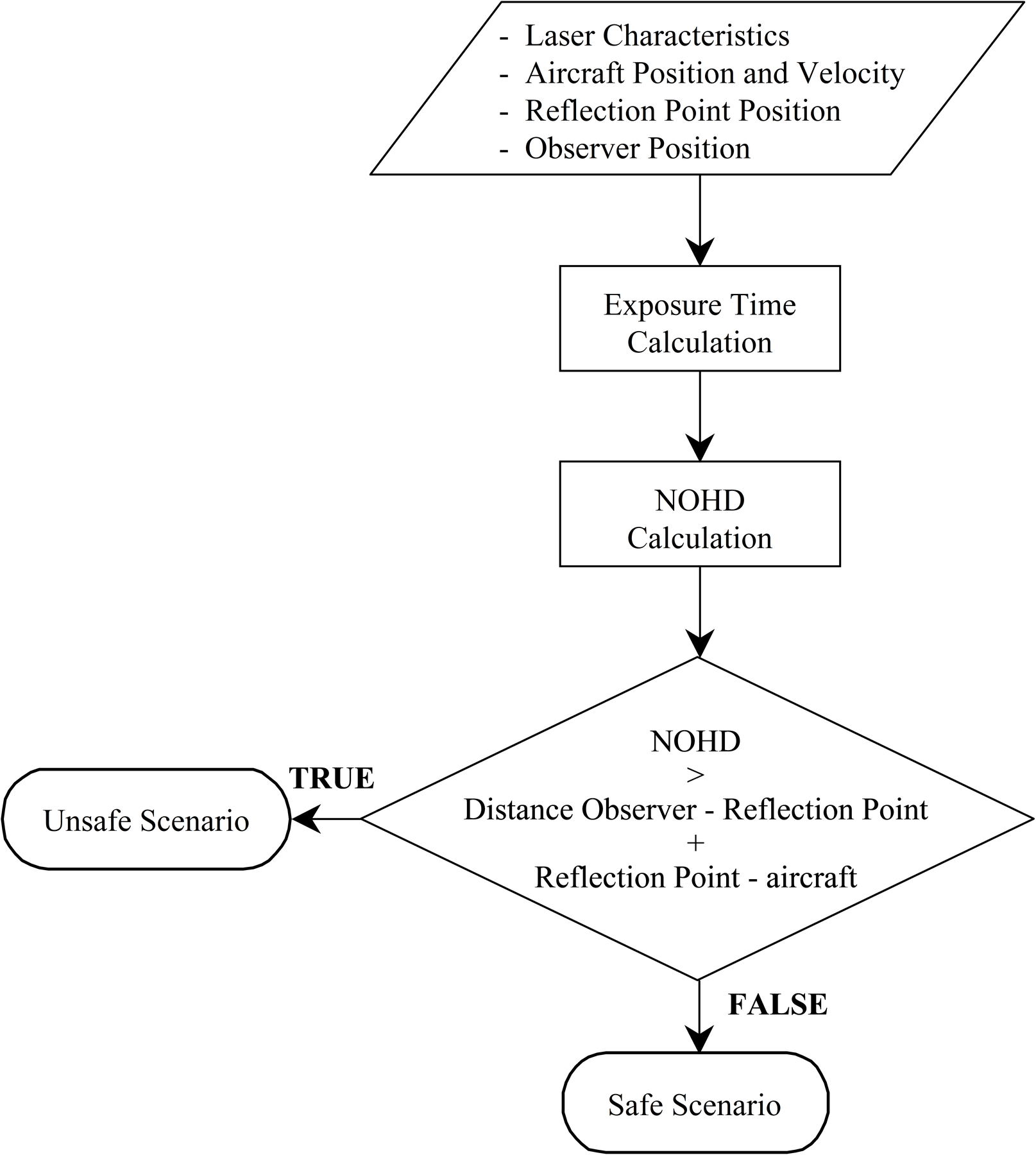
It was possible to verify the safety of a particular scenario by taking into account the aircraft position and velocity, the observer position, the reflection point and the laser characteristics, because the actual exposure time of an observer to the reflected laser radiation is a function of the reflected beam angular velocity (equal to aircraft angular velocity), the beam divergence and the distance between the observer and the point of reflection on the ground. Therefore, knowing the effective time of exposure (and hence the effective NOHD), safe or non-safe operation is determined by comparison of the sum of the distances of the observer to the point of the reflection and the point of the reflection to the aircraft.
The procedure described above is illustrated in Figure 11. Knowing the dimensions of the BZ, it was therefore possible to verify the observer’s safety, using the procedure described in an iterative manner for the entire BZ area.
The following underlying assumptions were adopted for implementation of the simulation program:
- reflecting surface (BZ) perfectly planar;
- laser beam reflection totally specular;
- entire BZ considered as a perfect (total) and specular reflector;
- atmospheric attenuation of the laser beam not considered;
- significant LOS instability during laser firing; and
- NOHD calculated for direct vision of a beam with Gaussian distribution.
It was also considered that no magnifying instruments were used in the test range.
Final Remarks
In this paper we have presented the activities carried out by the Italian Air Force Official Flight Test Centre in order to integrate the Thomson Convertible Laser Designation Pod and GBU-16/GBU-24 Laser Guided Bombs on the Italian TORNADO-IDS.
Once that electrical/mechanical compatibility of the sub-systems with the aircraft was assured, the kernel areas of testing of flight mechanics (handling and vibration), store separation, software algorithms and avionics/sub-systems were identified.
Test requirements contents, mathematical models and analysis tools were the guideline for defining the aircraft in flight data acquisition, telemetry systems and the related parameters to be recorded during tests.
Simulation was essential for correctly planning flight test activities, analysing flight test data and for verifying the validity of the models/algorithms loaded in the operational aircraft software. In particular, use of simulation tools allowed a full aerodynamics and safe-separation investigation, weapon aiming analysis, masking characterisation and definition, preliminary performance estimation, laser hazards determination and laser/ballistic safety assessment, with consequent significant speed-up in the systems integration activities.
Therefore, the adopted development/test methodology, which consisted in a continuous interaction between ground test, flight test and simulation, gave considerable benefits and introduced improvements in the process efficiency (development and test activity speed-up) and optimisation of flight test data gathering. Remarkable reductions of costs and time were therefore experienced.
Acknowledgment
Special thanks to L.Col G. Arpaia and Maj F. Guercio of the Italian Air Force, and to Mr F. Fouchard of Thomson Avionique (Paris).
References
[1] T. Elder & J. Strong. The Infrared Transmission of Atmospheric Windows, J. Franklin Institute. 1953.
[2] R. Langer, Signal Corps Report No. DA-36-039-SC-72351, May 1957.
[3] W. Middleton, Vision Through the Atmosphere, University of Toronto Press, 1952.
[4] R. Sabatini, “Tactical Laser Systems Performance Analysis in Various Weather Conditions”, NATO RTO CP-MP-1, March 1998.
[5] STANAG 3606—Edition V, Evaluation and Control of Laser Hazards, 1991.
[6] Italian Standard CEI—76/2—Edition II, Apparecchi laser—Sicurezza dalle radiazioni, classificazione dei materiali, prescrizioni e guida per l’utilizzatore, 1993.
[7] Italian Military Standard SMD-W-001, Regolamento Inteforze di sicurezza per l’impiego degli apparati laser, 1995.
[8] American National Standard Institute ANSI Z136.1, Safe Use of Laser, 1986.
[9] American National Standard Institute ANSI Z136.4, Laser Safety Measurements and Instrumentation, 1976.
[10] R. Sabatini, et al, “Tactical Laser Systems Performance Analysis and Mission Management”, NATO RTO-MP-46, April 2000.