
Volume 4, Number 2, July 2001
Preliminary Insight Into Aerodynamics Of Flapping Wing Micro Air Vehicles (mav) For Indoor Reconnaissance
Abstract
In this paper scaled-up wings of a fly are used with representative wing kinematics to analyse steady-state, inviscid flow in forward flight. The small (approximately 6 inches, or hand-held) reconnaissance micro air vehicles (MAVs) will fly inside buildings, and require hover for observation, and agility at low speeds to move in confined spaces. For this flight envelope insect-like flapping wings seems to be an optimal mode of flying. The investigation of the aerodynamics of flapping wing MAVs is very challenging. The problem involves complex unsteady, viscous flow (mainly laminar) with the moving wing generating vortices, and interacting with them. At this early stage of research only a preliminary insight into the nature of the little known aerodynamics of MAVs was obtained.
Introduction
The development of small (approximately 6 inches, or hand-held) autonomous flying vehicles is driven by a need for intelligent reconnaissance robots, capable of discreetly penetrating confined spaces, and manoeuvring in them without the assistance of a human telepilot [1,2]. This is particularly relevant to military operations in urban terrain (MOUT) [3].
Flight inside buildings, stairwells, shafts and tunnels has significant military and civilian value, and requires agility at low speeds to avoid obstacles and move in confined spaces. The vehicles can be used in dull, dirty or dangerous (D3) environments, where direct or remote human assistance is not practical. Non-military uses will include law enforcement and rescue operations. The ability to explore D3 environments without human involvement will be of interest for many industries, for example, allowing air sampling in inaccessible areas, and examination of confined spaces in buildings, installations and large machines. The flight envelope of MAVs requires high agility (including hover) at low speeds (1-2 ms-1) and silent flight, which is not easily met by scaled-down fixed or rotary wing aircraft. However, insect-like wing-flapping flight would appear to be very suitable for such applications requiring highly manoeuvrable flight through confined spaces [1,2].
Insect-like flapping
The unconventional aerodynamic concept associated with MAVs deserves a more detailed explanation. Insects fly by oscillating (frequency range: 5–200 Hz) and rotating their wings through large angles, which is possible because their wing articulation is not limited by an internal skeleton. The wing beat cycle can be divided into two distinct phases, the downstroke and the upstroke.
At the beginning of downstroke the wing (as seen from the front of the insect) is in the uppermost position with the leading edge pointing forward. The wing is then pushed downwards and rotated continuously resulting in large changes to the angle of attack. At the end of downstroke the wing is twisted rapidly so that the leading edge points backwards, and the upstroke begins.
During the upstroke the wing is pushed upwards and rotated again, changing the angle of attack throughout this phase. At the highest point the wing is twisted, so that the leading edge is pointing forwards again, and the next downstroke begins.
In forward flight the downstroke lasts longer than the upstroke, because of the need to generate thrust in addition to lift. In the hover, where lift only is required, the two strokes are of equal duration.
This mode of flying relies on unsteady aerodynamics [4], producing high lift coefficients (peak CL of the order of 3 is typical [5]), and excellent manoeuvrability. The unsteady mechanism varies with different insects, the most important being a bound leading edge vortex [6]. The high lift is a major factor in high efficiency of the mechanism: a typical power requirement for insects is 30 W/kg [7], whereas small, electrically-powered, propeller-driven, fixed wing aircraft require about 150 W/kg. Insect wing flapping occurs in a stroke plane that generally remains at the same orientation to the body, and may be horizontal or inclined. Rapid rotations occur at each end of the flapping half-stroke. To a first approximation kinematic control of insect flight manoeuvres is provided by changes in the tilt of the stroke plane, which is analogous to helicopter control. Precise control is achieved by including inter-wing differences in the magnitude of the force produced, the timing of the downstroke-to-upstroke wing rotation, and the geometric position of the wings when the rotation occurs.
Numerical modelling
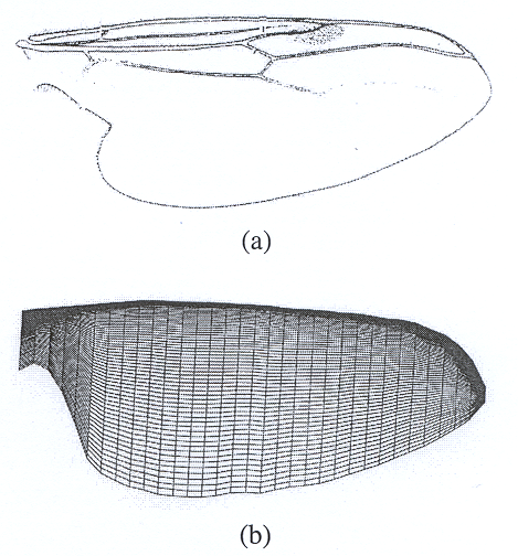
Sample calculations providing a preliminary insight into the aerodynamic behaviour of flapping wings have been performed for a low speed (7 ms-1) forward flight. These calculations used an in-house Euler finite volume code based on an artificial compressibility concept. Only quasi-steady calculations were conducted. At this stage the choice of the wing planform, the shape of aerofoils forming the wing, and the prescribed kinematics of movement, are still open questions. The aerodynamic design, and a thorough understanding of the physics involved, will be a subject of a long-term detailed study. In the presented calculations the choice of the planform has been inspired by the geometry of the wing of a Bibio fly. The potential choice of the generic geometry of the planform is illustrated in Figure 1(a). The actual geometry used in the calculations was simplified, and the corresponding computational mesh is shown in Figure 1(b). Semi-span is 126 mm long.
A constant aerofoil section was used along the wing span and scaled with respect to the local chord to fit the planform. A symmetric NACA0012 aerofoil with thickness decreased 0.3 times was chosen as a starting point for the investigation (Figure 2).

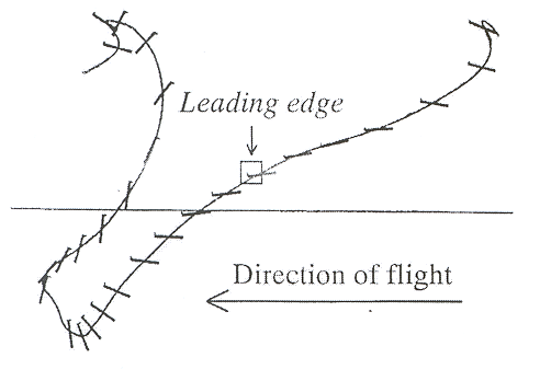
It is anticipated from observation of insects that the design of the final aerofoil sections will result in much thinner aerofoils, characterised by a sharp leading edge. The choice of wing positions to be investigated were dictated by typical changes of the rotational angles around the Cartesian x,y,z axes, with x,y defining the aerofoil plane, and z orientated from the root to the tip of a wing. The rotation angles were interpreted from the kinematics presented in Figure 3. More details are given in reference [9].
It was assumed that during one cycle:
- the rotation angle ? with respect to x will vary between -45? and 45?;
- the rotation angle ? with respect to y will vary between 0? and 120?; and
- the rotation angle ? with respect to z will vary between 20? and 130?.
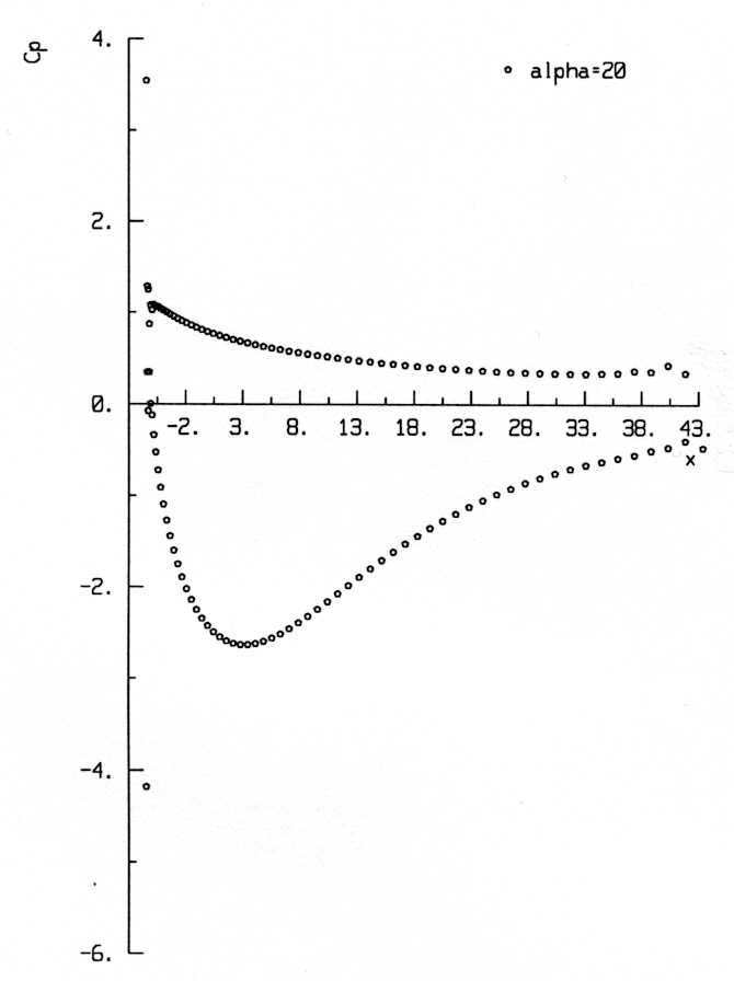
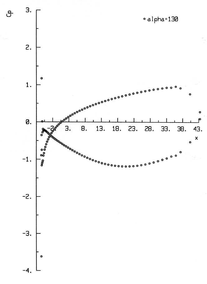
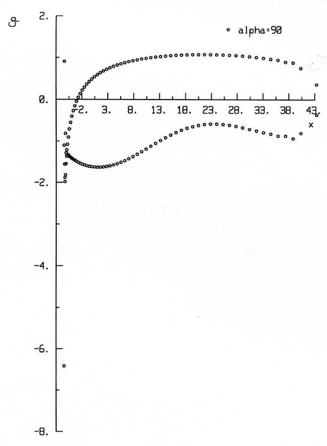
Pressure coefficient (Cp) distribution plots obtained from the calculations were very similar in character for most wing span sections between 25–75% span. Moreover, only minor changes were observed when the rotation angles, β and γ, were changed. However, changes of the wing incidence, α, had considerable effects, as expected. Representative Cp plots obtained for the 50% wing span sections and rotation angles β=40°, γ=0° are shown in Figure 4a, 4b and 4c for α=20°, 90° and 130° respectively. (Chord = 43.2 mm) In the Figure 4c (α=130°) it can be observed that for the values of Cp for the upper and lower surfaces changed sign, as compared with the other cases, thus resulting in negative CL. The corresponding values of the lift coefficient for this case are given in Table 1.
| Incidence angle α | Lift coefficient CL |
|---|---|
| 20° | 1.6168 |
| 45° | 1.0582 |
| 90° | 0.0422 |
| 130° | -1.0033 |
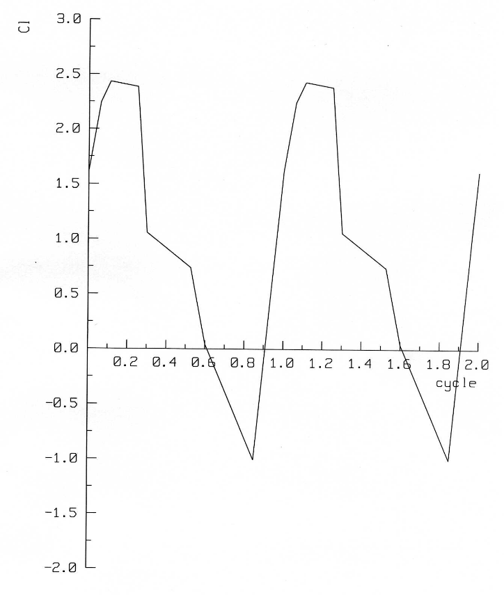
In order to reflect changes in CL in terms of typical kinematics of insect-like flapping, the quasi-steady values of CL were associated with their corresponding times in the flapping cycle, as shown in Figure 5. For this purpose, eight values of CL for varying incidence angle, α, were used. The maximum value of the lift coefficient, CLmax, was 2.44, and occurred at α=28.4°. Variations in the rotation angles, β and γ, had little effect on the magnitude of CL , with calculations showing differences in the second decimal place.
The values of CL obtained by the quasi-steady approach are substantially lower than those estimated from observations of insects, for which CLmax of the order of 3 is reported [5]. This underestimate is caused partially by the choice of aerofoil. However, based on the reported aerodynamic experiments [6] and numerical calculations of the hawkmoth Manduca sexta [8], it is most likely that the effect of a leading edge recirculation vortex has a significant effect on the flapping wing performance. Since this phenomenon is associated with unsteady movement of the wing, it could not have been investigated by the quasi-steady calculations. In order to provide an in-depth insight into the flapping wing aerodynamics, further work using a time accurate flow solver, with a dynamically moving wing, is necessary.
Conclusions
This paper reports the current status of a long-term project investigating aerodynamic aspects of flapping MAVs. The complexities of the physics of the flow have been highlighted. An initial quasi-steady numerical model has been developed and applied to an idealised insect-like flapping wing. Although the model provides some initial insight, it is insufficient to capture the important unsteady features of the real flow. A proposed extension of the code should alleviate this problem, and is the subject of current work.
Acknowledgement
This work has been supported by the EPSRC Grant GR/M78472 “Flapping Flight Aerodynamics of Autonomous Micro Air Vehicles”.
References
[1] R. Żbikowski, “Flapping Wing Autonomous Micro Air Vehicles: Research Programme Outline”, Proceedings of the Fourteenth International Conference on Unmanned Air Vehicles Systems, Vol. [Supplementary Papers], pp. 38.1–38.5, 1999.
[2] R. Żbikowski, “Flapping Wing Micro Air Vehicle: A Guided Platform for Microsensors”, Procedings of Royal Aeronautical Society Conference on Nanotechnology and Microengineering for Future Guided Weapons, pp. 1.1–1.11, 1999.
[3] N. Baker, J. Campbell, G. Finch, and R. Green, “The Utility of Micro Air Vehicles”, No 3 Defence Technology Course (MA) Report, WVM/1167/99/05RMCS Shrivenham, 1999.
[4] C. Ellington, “Unsteady Aerodynamics of Insect Flight”, in C. Ellington and T. Pedley (eds), Biological Fluid Dynamics, Vol. 49, pp. 109–129, 1995.
[5] M. Dickinson, F. Lehmann and S. Sane, “Wing Rotation and the Aerodynamic Basis of Insect Flight”, Science, Vol. 284, No. 5422, pp. 1954–1960, 1999.
[6] C. Ellington, C. van den Berg and A. Thomas, “Leading-edge Vortices in Insect Flight”, Nature, Vol. 384, No. 6610, pp. 626–630, 1996.
[7] R. Dudley and R. Srygley, “Flight Physiology of Neotropical Butterflies: Allometry of Air Speeds During Natural Free Flight”, Journal of Experimental Biology, Vol. 191, pp. 125–139, 1994.
[8] H. Liu and K. Kawach, “A Numerical Study of Insect Flight”, Journal of Computational Physics, Vol. 146, No. 1, pp. 124–156, 1998
[9] J. Pringle, Insect Flight, Oxford University Press, Glasgow, 1975.