
Volume 4, Number 2, July 2001
The Computational Study Of The Aerodynamic Design Of A Segmented Rod Projectile
Abstract
A purpose of this study was to provide an enhanced understanding of typical impact and aerodynamic behaviour of segmented rod projectiles. A range of designs was examined by computational modelling. In all cases the segments have been treated as a dynamically changing configuration of free-flying bodies separated at launch. The paper highlights difficulties of this approach showing that, prior to impact, the segments rapidly lose alignment, which reduces effectiveness of penetration. Investigation of alternative design concepts is recommended.
INTRODUCTION
The long-rod penetrator that utilises the advantage of the high launch velocity is, at present, the dominating type of kinetic energy (KE) penetrator. It has a penetration capability in homogeneous targets that approaches a limit value at velocities close to 2,000 m/s. As the velocity increases, the KE produces a wider, rather than a deeper, penetration channel [1]. To overcome this limitation unconventional projectiles such as the segmented rod projectile—the emphasis of this paper—and the telescopic projectile have attained the greatest attention.
At velocities above 2,000 m/s, both segmented and telescopic penetrators give deeper penetration in steel armours than a homogeneous conventional projectile with the same initial geometry [2-3]. An in-depth study of the penetration of segmented projectiles also has been conducted by the authors [4].
Designing segmented rod projectiles to impact the target at the same point, one after another, in a straight line, is a problem for ammunition designers. Detailed consideration must be given to ensure that:
the velocity of the projectile is maintained throughout the flight;
the projectile can withstand the intense aerodynamic heating from travelling through the atmosphere at hypervelocity, without being destroyed or deformed; and
the dispersion of the projectile trajectories around the nominal flight path is small enough to assure target hits.
The retention of the trajectory of the flight requires the segments to be in line, with minimum yaw, and with the separation maintained until impact. Any misalignment in the segments will reduce the effectiveness of the penetrator. In this paper, the feasibility of designing a segmented rod projectile that can fulfil the above requirements is examined. The results presented are based on calculations carried out assuming that the segments are separated immediately after leaving the muzzle.
Studies that examine the aerodynamic characteristics of segmented projectiles have not been extensively conducted before. Preliminary investigations were reported in [5-8]. Our analysis exploits Computational Fluid Dynamics (CFD) code, [9] that provides a cost-effective and fast turn-around approach for analysing the aerodynamic behaviour of segmented projectiles in flight.
In the choice of computational method, the simplifying assumptions of two-dimensional and inviscid flow have been made. The validity of such assumptions for the extremely complex aerodynamics of segmented projectiles, and their limitations, were discussed in [10]. In effect, this method can not provide accurate predictions, but is suitable for estimations and should be viewed as an engineering tool.
A numerical analysis has been compared to the determination of the alignment of the segments resulting from a physical impact experiment (conducted previously to compare the segmented projectile penetration performance against a continuous projectile). The experiment involved the impact of a five-segment projectile of EN31 steel fired into a BS968 steel cylindrical target. The target was cut to measure the penetration (see Figure 1 drawn from the original photograph).
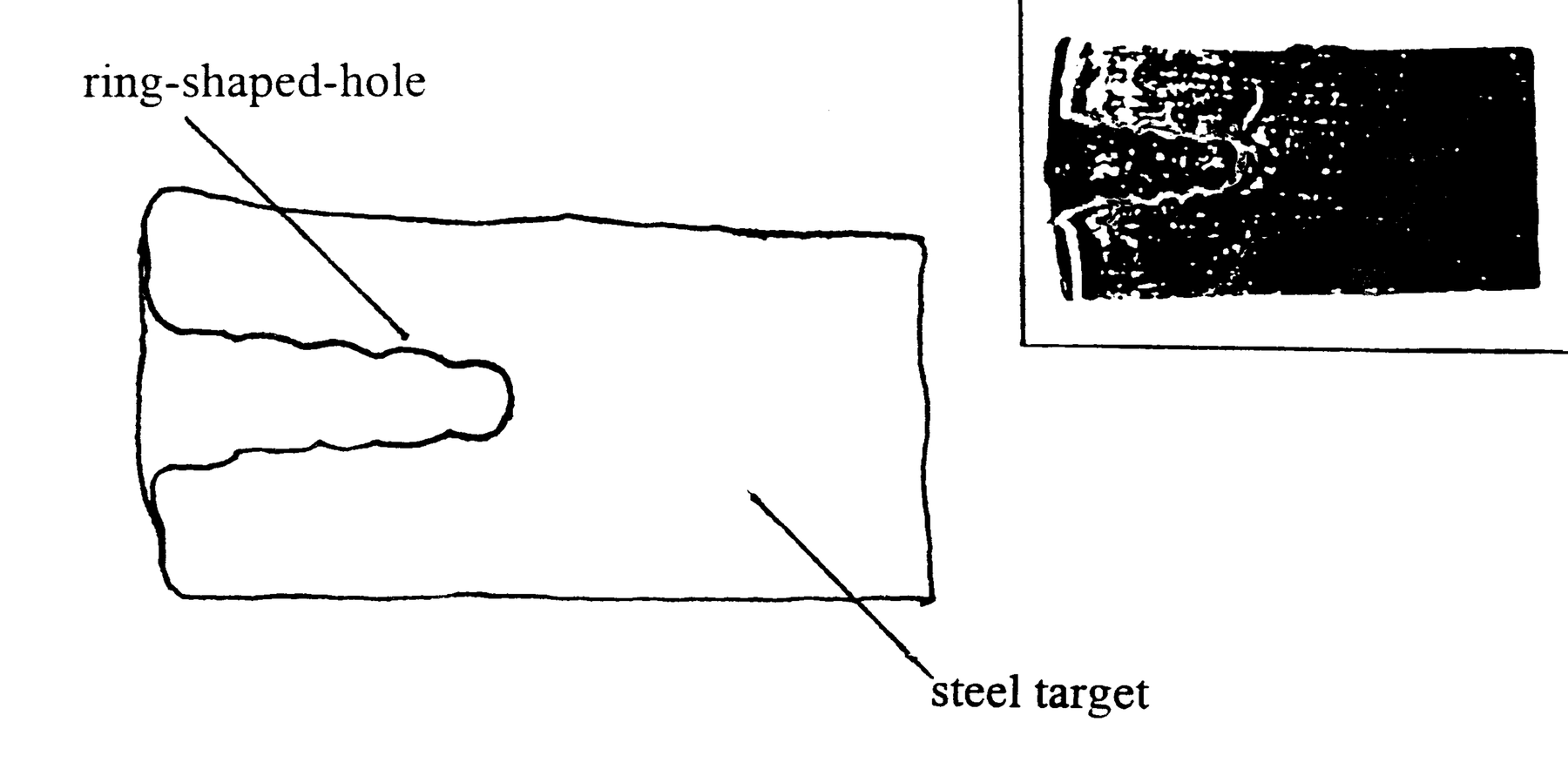
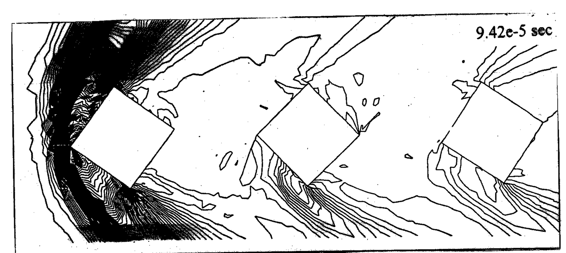
The cutout of the target shows, as expected, a five-ring-shaped-crater, which characterised the penetration of the five-segment projectile. It also reveals that the rings are different in size, that they are distorted and that their centres do not form a straight line. The possible interpretation needs to take into account the trajectory of the segments immediately prior to impact. The difference in the ring size and their distortion can be explained by the different yaw angles of the impacting segments. Additionally, the non-alignment of the centres of the rings is likely to reflect the vertical lateral separation of the segments. In the numerical analysis depicting the experiment, a three-segment projectile was used. The distance covered by the leading segment was 0.18 m from the muzzle. The sample contour plot of the projectile at 9.42e-5 s is shown in Figure 2. In all computations, at the moment of impact, a small vertical displacement between the segments was calculated. However, the segments still stayed approximately aligned. The value of the angular displacement due to yaw of the segments were significantly different. This agreed with the interpretation of the shape of penetration crater obtained in the experiment.
AERODYNAMIC DESIGN
At this stage, the aim was to explore practicality of the concept that the segments can be treated as a dynamically changing configuration of free-flying bodies separated at launch. A substantial number of calculations, using the code, has been conducted. A large selection of preliminary designs and corresponding detailed results is provided in [11]. Our investigation has focused on the flows that were not axi-symmetric. Due to the two-dimensionality of the computational method, neither finned nor spinning projectiles could be evaluated with good reliability.
A study of the influence of varying the design parameters, the thickness of the leading segment, the separation between segments, the nose radius of the leading segment (Figure 3) and the radius of the trailing segment was conducted. In particular, the investigation of the aerodynamic behaviour of a two-body segmented rod, at Mach 7 at an initial yaw angle of two degree, results in following observations:
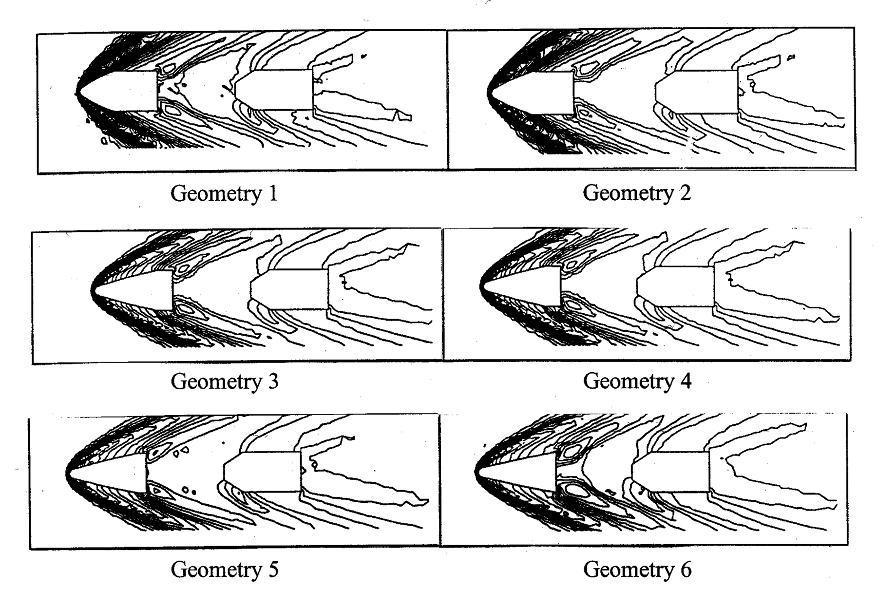
At typical distance, the aerodynamic loads of the leading segment in the system are higher than the loads of the segment calculated in isolation. The result shows that the presence of the trailing segment affects pressure forward of its local flow, hence influencing the aerodynamics of the former. The distance between the centre of pressure and centre of gravity is larger, hence reducing its stability.
The yaw rotation of the segments is caused by the resultant force acting on the centre of pressure of the segment relative to its centre of mass. The leading segment, having experienced the shock-wave on the nose end, rotates excessively compared to the trailing segment. A gradual slow rate of rotation is experienced by the trailing segment. This is due to the small difference in absolute pressure between the wind-side and the lee-side of the segment. A typical mutual movement of segments for unstable projectile, calculated for three segments, is provided in Figure 4.
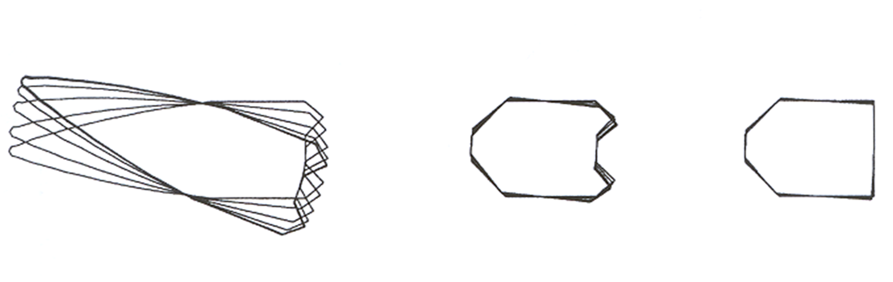
The leading segment is exposed to a much higher pressure, hence providing a much higher drag compared to the trailing segment. As a result, the flow around the leading segment tends to decrease in speed so, while the speed of the leading segment slows, there is less reduction in the speed of the trailing segment. Throughout the duration of the flight time, the leading segment slows down faster than the trailing segment, hence the trailing segment will close and, perhaps strike the leading segment before impact with the target.
A slender leading segment causes the shock-wave angle to reduce. The flow behind the shock-wave is, therefore, little reduced by the presence of the leading segment’s shock-wave. The resultant faster flow over the trailing segment increases its local Mach number, forming a bow shock between the segments. A thicker leading segment produces a bigger shock-wave angle. Increasing the leading segment’s diameter, or nose angle, has the converse effect.
Another effect of increasing the leading segment’s diameter is the increase in its drag. Its velocity reduces severely, and since the drag of the trailing segment is relatively small, the separation between the segments quickly reduces.
Increasing the rear segment’s diameter exposes its frontal surface area to more airflow. Higher pressure is exerted on the area, increasing its drag.
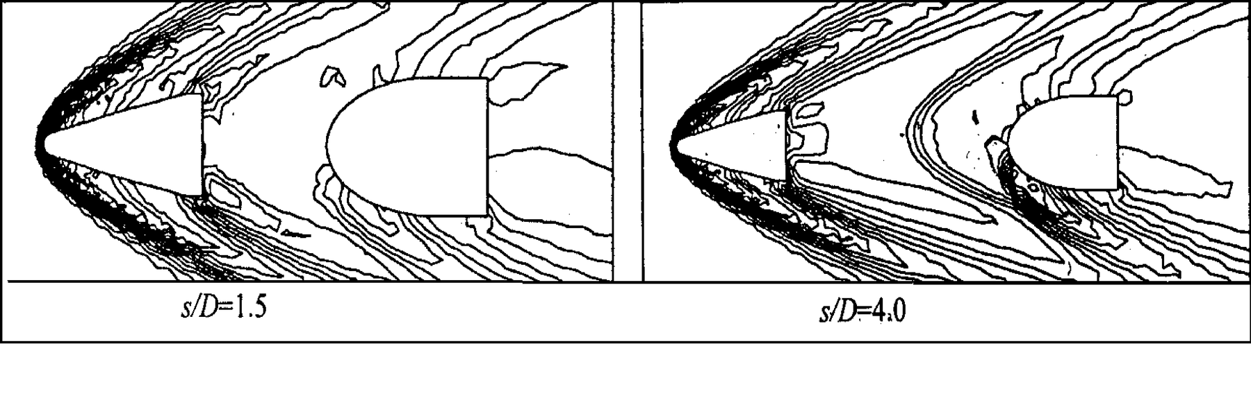
By increasing the distance between segments, the trailing segment is immersed in a faster flow region, so increasing its drag. An increase in the drag pushes the boundary layer forward of the segment’s nose, forming a local bow-shock. An example of the change in pressure contours for different distance between the segments is shown in Figure 5.
Increasing the flow Mach number around the segments body reduces the shock-wave angle in front of the leading segment. The difference in the flow speed between the region in front of and behind the shock layer reduces as the angle reduces. The flow speed behind the shock wave is still supersonic and the pressure differential between the upwind side and the lee side reduces, resulting in more stable segments.
The formation of a shock-wave in front of the trailing segment is caused by the re-establishment of supersonic flow in the leading segment’s wake. The second shock-wave brings instability not only to the trailing segment, but also to the leading segment. Both segments experience a drastic increase in the rotation rate.
In all calculations conducted on the non-stable projectile, the distance between segments reduces for a period of time before the leading segment loses its co-axiality. The rate of the rotation of each segment is based on the distance between its centre of pressure and its centre of gravity. A slimmer leading segment tends to rotate more readily than a thicker one.
In the design of the segment’s configuration a centre of pressure aft of the centre of gravity ensures a low rotation of both segments. Segments having a short-cylinder or spherical form have a great potential to provide viable solutions. The penalty is that both forms produce a high drag. In a prolonged period of flight, the projectile comprising short cylinders and spheres will decrease in penetrator separation such that the trailing segment hits the rear of the leading segment. Thus there is a need to deploy such a projectile only a short distance prior to impact.
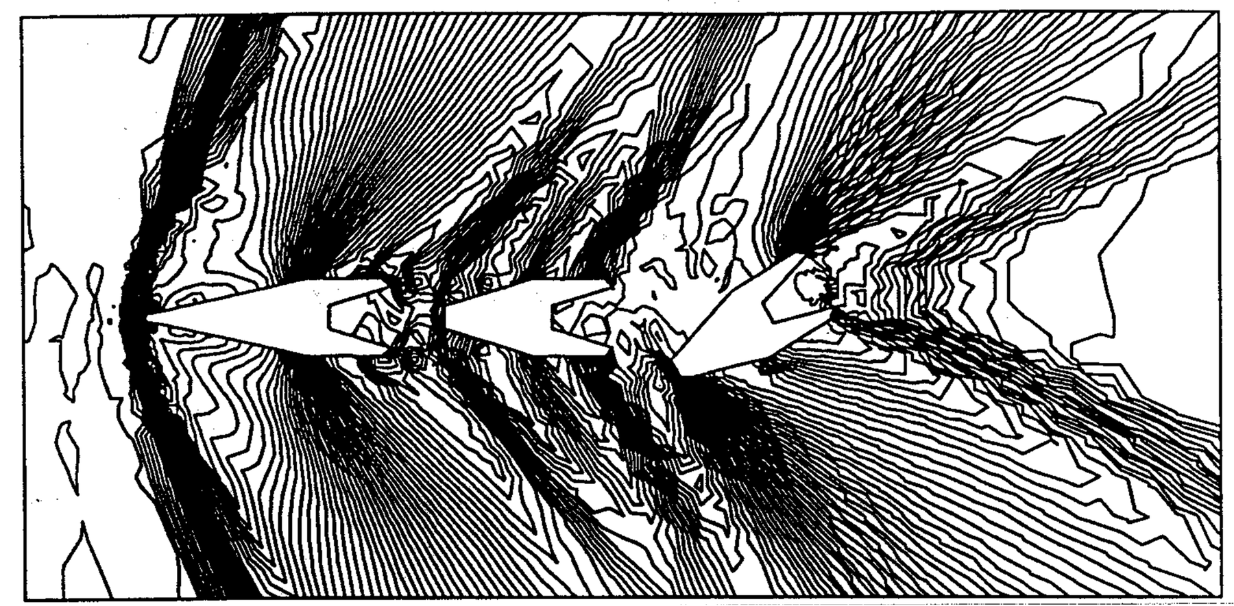
In a separate exercise a triple-bodied segmented rod was investigated. The calculation was conducted at low Mach number (M=1.2) and zero incidence. During calculation instabilities present in the wake, even in the inviscid solution, resulted in the second segment yawing but, after a series of oscillations, the segment returned to the straight flight. Similar instability in the wake resulted in considerable rotation for the third segment, which is illustrated in Figure 6. The segments are geometrically identical. The flow around the second body is supersonic, evidenced by the cone shape of the pressure contours created due to the shape of the flat body nose. The local flow around the third body is subsonic. The position of the center of pressure with respect to the center of gravity depends on the local Mach number, and is critical in the segments stable behaviour.
The aerodynamic analysis conducted in this study highlighted three main difficulties.
The main factor affecting the flight of the segmented rod projectile is the difference in drag between the segments that leads to the decrease in the separation during the flight. A blunt leading segment slows down faster than a sharp one. The rate of the decrease in the speed of the trailing body is much smaller, owing to the slower relative flow, so the drag coefficient, Cd, is about 10 times lower than that of the leading segment. The rate of the decrease in the distance is proportional to the bluntness of the leading body. All calculations give a similar trend. Reducing the diameter and increasing sharpness further will effect the penetration performance and increases the thermal effect on the leading segment. This makes the task of maintaining the distance between segments by aerodynamic means almost impossible. This fact has not been investigated before and has not been given adequate emphasis in previous research. The general opinion is that it is the formation of the wake at the rear of the leading segment, which is the main factor in the instability of the trailing segment. The influence of the wake’s formation between the segments has been proven by earlier findings of other studies [7-8].
The second factor is the yaw motion of the segment that is influenced by the position of the centre of pressure and the centre of gravity and the difference in surface pressure between the upwind side and the lee side. To reduce the drag of the leading segment, a sharp thin shape is preferred. This increases the distance between the centre of pressure and the centre of gravity significantly, and so may compromise stability.
The third factor is the instability due to the formation of the bow shock in front of the trailing segment. The transition between the change of the flow regime creates a highly unstable region. The possibility of both segments being affected is great.
CONCLUSIONS
With the advancement in the launcher technology, the segmented rod projectile has a great potential for defeating modern armour. It offers superior penetration performance compared to the long rod penetrator.
The concept of aerodynamic design was investigated in which segments were treated as a dynamically changing configuration of free-flying bodies separated at launch. In our experience achieving a design stable across varying flow conditions proved to be very difficult. Therefore, investigation of alternative design concepts is recommended.
Designing the segmented rod with the centre of pressure aft of the centre of gravity would result in stable segments. Spheres and short cylinders provide potential solutions to the problem, but these are high-drag bodies, and the rate of the decrease in the distance between segments is exacerbated. These factors demonstrate the difficulties in maintaining segment separation by aerodynamic means.
The problem of maintaining the distance between segments is the major factor that needs to be resolved. Forced separation techniques using propellant, springs, or telescopic rods may provide a workable solution. The use of a spring separator encased in a telescopic tube provides a projectile that can be deployed immediately on leaving the muzzle.
References
[1] C. Brissenden, “Performance of Novel KE Penetrator Designs over the Velocity Range 1600m/s”. to 2000m/s’, 13th International Symposium on Ballistics, Stockholm, Sweden, Vol. 3, pp. 185-192, 1992.
[2] A. Charters, T. Menna and A. Piekutowski, “Penetration Dynamic of Rods From Direct Ballistic Test of Advanced Armour Component at 2-3km/s”, International Journal of Impact Engineering, Vol. 10, pp 93-106, 1990.3.
[3] V. Hohler, and A. Stilp, “Penetration Performance of Segmented Rods at Different Spacing—Comparison with Homogeneous Rods at 2.5km/s to 3.5km/s, 12th International Symposium on Ballistics, San Antonio, Texas, USA, Vol. 3, pp. 178-187, 1990.
[4] S. Abdullah, J. Hetherington and D. Leeming, “Penetration Performance of Segmented Rods—Comparison with Continuous Rods at High Velocity”, Journal of Battlefield Technology, Vol. 1, No. 1, March 1998.
[5] C. Berner, “Aerodynamic Interference Between Tandem Projectiles; Measurement and Computations”, 14th Int. Symp. on Ballistics, Quebec, Canada, 26-29th September 1993.
[6] J. Sahu and J. Nietubicz, “Application of Chimera Technique to Projectiles in Relative Motion”, Journal of Spacecraft and Rockets, Vol. 32, No. 5, Sept-Oct 1995.
[7] D. Young, “A Study of Segmented Projectile Aerodynamics”, 48th Aeroballistic Range Association Meeting Proceedings, 5-9 November 1997, Austin, Texas.
[8] D. Young and D. Goldstein. “A Study of Unsteady Hypersonic Projectile Aerodynamics”, AIAA Paper No. 99-3379, 1999.
[9] J. Szmelter and S. Abdullah, “A Trajectory Prediction for Segmented Projectiles Using CFD Code”, Journal of Battlefield Technology, Vol. 2, No. 2, July 1999.
[10] J. Szmelter and S. Abdullah, “Estimation of Components Relative Motion in Segmented Rods”, 18th International Symposium on Ballistics Proceedings, San Antonio, Texas, November 1999.
[11] S. Abdullah, “Segmented Rod Projectile Design Approach”, PhD Thesis, Cranfield University, RMCS, January 2000.