
Volume 4, Number 1, March 2001
The Effect of Shock Waves Caused by a Penetrating Projectile on Simulated Blood-Vessel Systems
Abstract
This article contains an analysis of the effects of shock waves caused by penetration of a small calibre projectile through simulated human tissue and blood-vessel system. Results of experiments that have been carried out at the Military Academy in Brno are shown. A small calibre projectile was fired into a model of the part of the lower limb and the response of the blood-vessel system to a non-complicated injury has been evaluated.
Introduction
Literature concerning wound ballistics [1,2] shows relatively large amounts of information on the effects on both live tissue and their artificial substitutes. On the other hand, there is relatively little information about the non-direct effects of penetrating projectiles and fragments on the human blood-vessel system, especially when the projectile moves in close proximity to the large blood vessels without a direct hit. The aim of the work described in this paper was to investigate the terminal ballistic effects of small calibre ammunition using simulated human tissue and human blood vessel system, in particular, to:
- verify the suitability of the model and instrumentation for this type of investigation.
- assess the predictive capability of the model.
Secondary aims were to:
- evaluate the behaviour of the artificial tissue, mainly its ability to transfer energy associated with shock wave caused by the projectile penetration.
- measure the pressure extremes in the artery, and to use this data to predict the effect of the projectile on an artery in close proximity to the wound path.
The experiment was designed to simulate a non-complicated injury of the thigh, that is, when the projectile hits only the soft tissues, missing both the thighbone and the artery.
Tests were carried out using a 7.62 mm calibre test rifle and a 357 Magnum revolver.
Physical model
A physical model of part of a thigh was designed, comprising a block of substitute tissue and an artificial artery. The following materials were used to simulate the behaviour of live tissue:
- A 20%-gelatine solution (G-20).
- A mixture of petroleum and paraffin waxes in the ratio 75%:25% (PP 75/25).
- Plasticine-grey modelling material (PL).
The physical characteristics of these materials are shown in Table 1, and were obtained from tests carried out at the Military Academy in Brno, Weapon Systems Department according to [3] and [4].
Cylindrical samples of G-20 and PP 75/25, with a diameter of 15 cm and a height of 20 cm, were prepared by casting and allowing the material to solidify at room temperature. Any cavities arising during solidification of PP 75/25 were eliminated manually. The PL samples were made by ramming the material into a wooden mould, 15x15x20 cm. The samples made from PP 75/25 and PL were held at an ambient temperature of 21°C; sample G-20 was held at a temperature of 5°C, which is temperature advised for use of this material by the manufacturer.
| Substitute materials | ||||
|---|---|---|---|---|
| Characteristics | Unit | PP 75/25 | G–20 | PL |
| Density | kg/m3 | 933 | 1100 | 1710 |
| Creep index | - | 0.643 | 0.605 | 0.866 |
| Dyn. viscosity | 10-3 Pa s | 10.98 | 4.47 | 13.79 |
| Specific. acoustic impedance | 10-6Pa m-1 s | - | 1.73 | - |
The speed of sound was only available for the G-20 material and so the acoustic impedance could be found only for this material. The values of the acoustic impedance of pig tissue (1.79 10-6 Pa m-1 s) and the G-20 are in sufficient agreement.
The thigh artery was modelled by a thick-walled silicon duct of outer diameter, 2R, of 10 mm and wall thickness, t, of 2 mm, placed along the longitudinal axis of the sample.
None of the samples was designed with a thighbone. The entire hydraulic system, simulating the blood-vessel system, was filled with a replacement blood (colloid infuse detergent Gelafundin). A hydrostatic pressure was created, and the air removed from the system before firing.
Hydraulic measurement and record of pressure in blood-vessel
The propagation speed of a pressure wave in a duct filled with water depends on the modulus of elasticity, E, of the duct material and on the radius to wall thickness ratio, R/t. The modulus of elasticity, E, for the duct material used was obtained from measurements performed in laboratories at the Military Academy in Brno (Department of Aircraft and Engines) and is 7 MPa for an R/t value of 2.5.
Figure 1 shows curves representing ducts of different R/t with a range of values of modulus of elasticity, E, for commonly used artificial duct materials. From this data the speed, c, of the pressure wave for the duct used is 40m/s, and corresponds to a duct with a very soft wall filled with incompressible liquid.
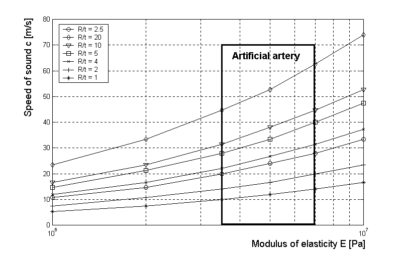
Figure 2 shows a schematic arrangement of the experimental rig. Piezoelectric transducers DMP 331 (measuring range from –100 kPa to +700 kPa for gauge G1 and from –100 kPa to +100 kPa for gauge G2) were used to give continuous pressure-time data for the artificial artery. The location of both gauges G1 and G2 was chosen to give the best possible measurement of the spreading of the shock wave inside the measured object.
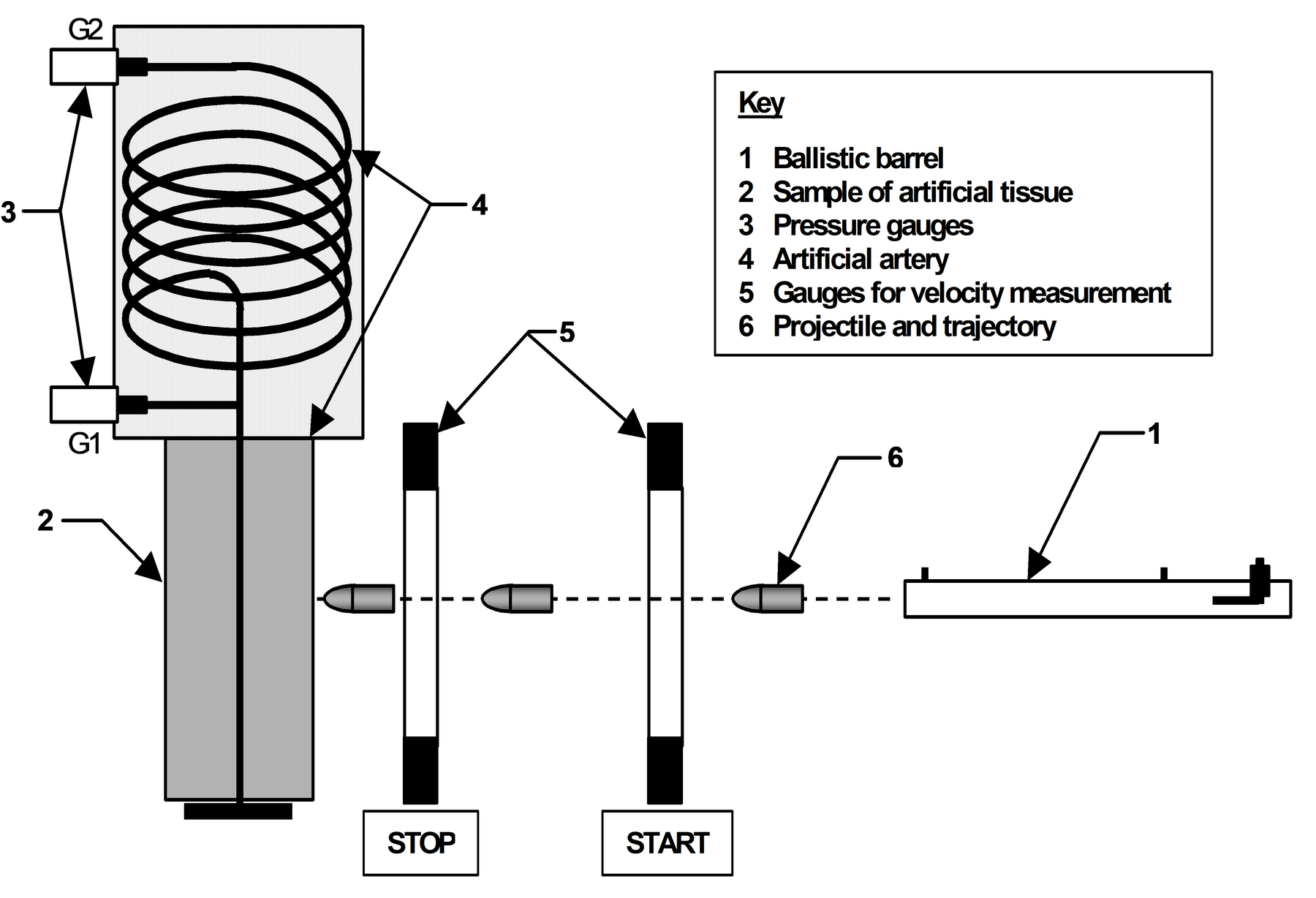
The gauge G1 was placed on the artery, close above the measured sample, at a distance of 10–20 cm above the expected position of the wound path. The gauge was connected to the artery by a heavy brass T-piece to prevent distortion of the curve of the pressure peak.
The artery was closed at the bottom of the sample. The open top emptied into a container (diameter 25 cm) above the sample, where the artery (length 110 cm) was coiled into a helix. The gauge G2 was also placed at the end of the artery by connecting a brass T–piece with a valve to enable filling of the system with Gelafundin to create the required hydrostatic pressure in the system. The space between the container and the artery was filled with sponge material, covered by a lid and weighted with a 5 kg weight. This feature was designed to simulate the blood pressure and the tension in muscle tissue. A simulated blood pressure of 9 kPa (67 mm Hg) on gauge G1 and 7 kPa (52 mm Hg) on gauge G2 was achieved. These pressures were slightly lower than was required.
A dual recording system was used. For the main system each of the signals from the two gauges, G1 and G2, was sampled at 10 kHz for a time to give 7000 values. This sampling frequency and number of recorded values was considered sufficient for detailed display of the measured pressure-time curves.
A second back-up system used a digital oscilloscope HP 54 645A to give a graphical recording of the pressure-time curves from each of the pressure gauges G1 and G2. Because the gauges had different operating ranges the back-up system gave only qualitative information on pressure values, although the location of the pressure various peaks in the time domain can be compared.
Ballistic characteristic of experiment
The artificial thigh and artery, with its gauges, was supported by a stand to ensure stability during projectile penetration. Two rounds were fired into each sample such that the whole bulk of the sample was exploited but without the results of one being affected by the other.
For the firing trials the following rounds were used:
- Rifle ammunition (for assault rifle SA 58) of calibre 7.62x39 (Mk 43) with a FMJ (full metal jacket) projectile (weight 7.9 g). Rounds of standard design were fired from a test ballistic barrel (muzzle velocity 750 m/s, muzzle kinetic energy 2220 J). The distance between the muzzle and the sample was 5 m. The velocity of the projectile was measured by non-contact induction gauges and optical gates at a point 3 m from the muzzle, and can be considered as the impact velocity since it is close to the sample.
- Revolver ammunition of calibre 375 Magnum (Eldorado PMC) with an HP (hollow point) projectile. This ammunition was fired from a Taurus revolver with a 3 in. barrel (muzzle velocity 340 m/s, muzzle kinetic energy 560 J). The distance between the muzzle and the sample was 3 m. In this case the velocity was measured by optical gates alone, at a point 2 m from the muzzle. This can also be considered as the impact velocity.
The aiming point on the sample was chosen for both types of ammunition so that the projectile penetrated at a distance of 3–4 cm from the tested artery. In both cases the projectiles perforated the sample, that is, exited from the far side with a significant residual kinetic energy. It was not possible to measure the residual energy due to the limited capabilities for measuring projectile velocity after exit from the sample.
Results achieved
Examples of captured results of pressure-time curves are shown in Figures 3, 4, and 5. The results shown in Figures 3 and 4 were carried out on a model thigh made from G-20. The model made from PP 75/25 did not provide any measurable results, despite fully functional measuring system. Unfortunately, technical problems with the PL model were such that it was totally destroyed by the first hit with the 7.62 mm FMJ projectile, and no signal was captured by the main recording system. A back up signal was captured by the secondary system but give only qualitative information, as shown in Figure 5. Although no scales are shown, similarities between the signals shown in Figure 5 and the results from using the G-20 samples, Figures 3 and 4, are clearly evident. However, values of pressure peaks for experiment on PL are not available.
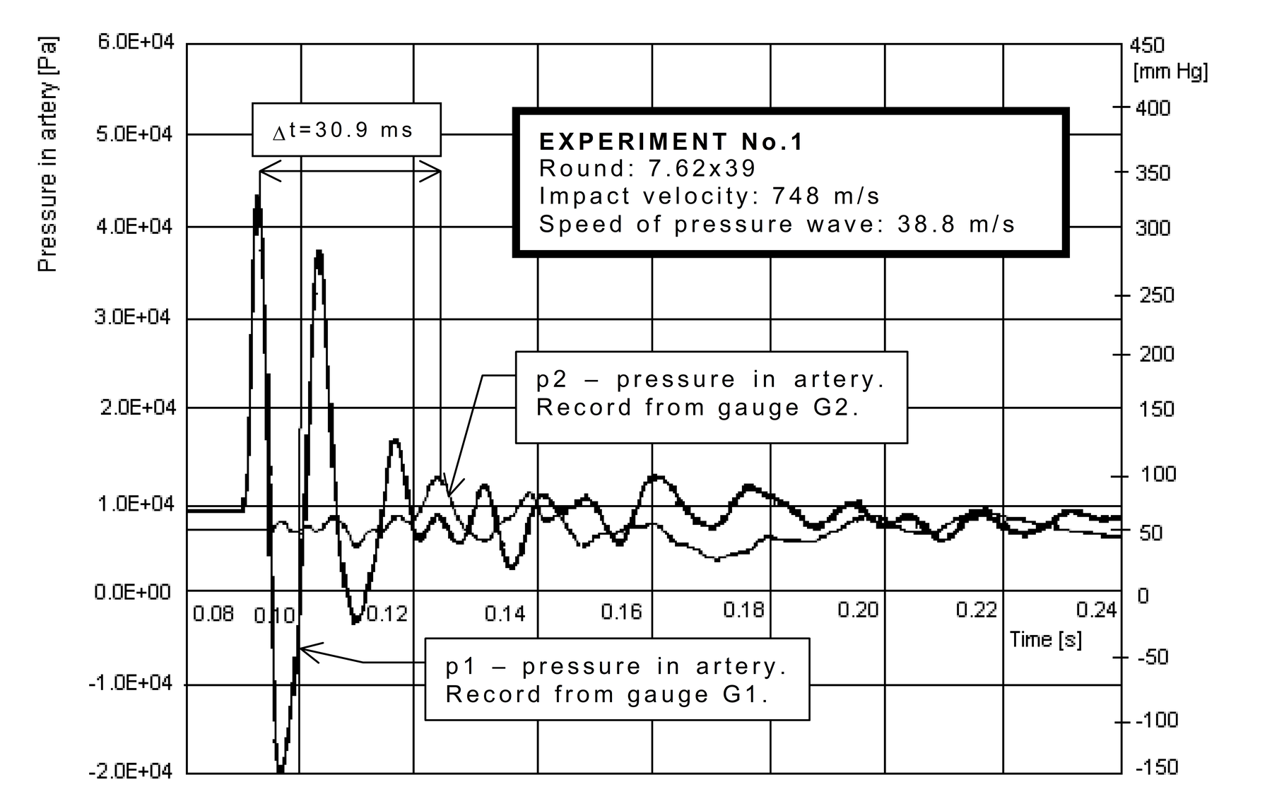
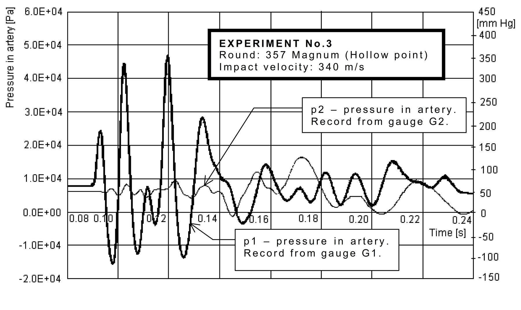
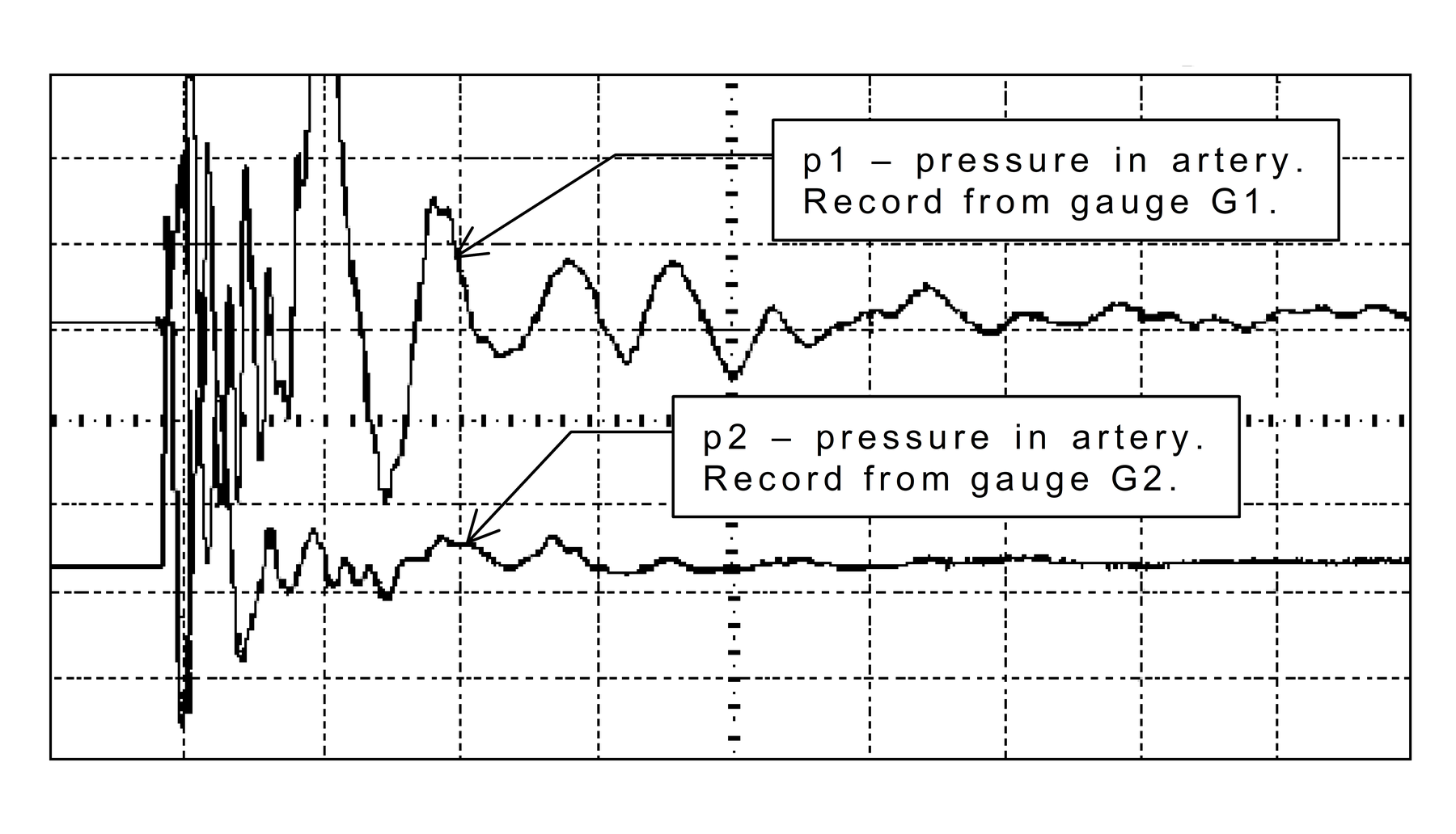
The steep increase in pressure p1 in the artery is characteristic for measured pressure-time curves. Average speed of pressure increase reaches 8–10 MPa/s and peak pressures exceeds 30–40 kPa. For the 357 Magnum projectile the peak was nearly 50 kPa. A steep increase in pressure is followed by an equally steep drop to values between –10 kPa and –20 kPa. In the case of the 7.62 mm projectile, the increase in pressure after those first two extremes is not so significant and, after several damped oscillations, the pressure becomes constant. In the case of the 357 Magnum projectile the absolute pressure peak is shifted after the first local maximum pressure. Total duration of the event did not exceed several tenths of a second, and the pressure dropped to under 10 kPa in 0.05 s.
The pressure peaks measured by the second gauge G2, pressure p2, at a greater distance from the point of impact are significantly lower (less then 13 kPa). This is to be expected since high elasticity of both the artificial tissue and walls of the artificial artery cause significant drop in pressure with increasing distance from the point of impact.
The speed of spread of the pressure wave, v = 39 m/s, in the artificial artery was found from the delay between maximum pressures p1 and p2, see Figure 3. This value is in very good agreement with the value read from Figure 1 described earlier.
The projectiles were captured by a block of cotton waste after each penetration of the sample to evaluate any changes in shape. The FMJ 7.62 mm projectiles penetrated the sample without any deformation. The HP 357 Magnum projectiles expanded during penetration of the samples. For the G-20 sample the expanded diameter was about 17 mm, which corresponds to a coefficient of expansion 1.89. The remaining weight of the projectiles was 9.55 g, which is 98% of the original weight.
The results captured during these experiments may be influenced by resonances in the system, and this would need further investigation.
Mechanism of penetration of the sample with the artificial artery
Shock waves are created during penetration of the sample containing the artificial artery, spreading at the speed of sound. These shock waves transfer energy into surrounding structures, particularly in the direction of the projectile motion, but also in the radial direction. This mechanism creates a temporary cavity in the area of projectile penetration. The overpressure at the shock wave front causes compression of the material, including arteries, and damage to the tissue, followed by rupture of the arteries and nerves, even at significant distances from the wound path.
The overpressure phase, lasting several microseconds, is followed by a phase of underpressure during which the temporary cavity collapses. Subsequent pulsation of the temporary cavity affects the pressure inside the artery (alternation of underpressure and overpressure phases). The whole process decays within several tenths of seconds, and the permanent cavity is created.
Medical assesment of effects
The pressure difference of 60 kPa (450 mm Hg) caused by the combined effects of an overpressure of 40 kPa (+300 mm Hg) and an underpressure of -20 kPa (-150 mm Hg) inside the simulated thigh artery could cause the following pathological changes:
On the artery
- damage of endothelium with negative consequences (micro-embolism, later scaring of artery)
- break away of arteriosclerosis plate with possibility of sequential embolic complications
- damage of peripheral vessels, creating a blood clot in capillaries.
On the whole organism
- shock increase caused by reflex mechanism during damage to the artery.
Damage to the artery caused by the combined effects of internal over-pressure and under-pressure are likely to be less significant than any direct damage due to the effect of the shock wave spreading in tissue in close proximity of the wound track. The artery was pushed to one side and stretched by the effect of the shock wave, which could result in rupture of the wall after exceeding the elastic limit. The artificial artery was not damaged during experiments due to its higher mechanical strength.
The magnitude of pressure peaks decreases with increase in distance from the point of impact (on gauge G2 the measured maximum pressure was less than 13 kPa (100 mm Hg)). It is possible that the function of the heart and other vital organs will not be significantly affected by these changes in pressure.
For a real artery, any damage is likely to be more severe during hypertension, and for an artery which has developed sclerotic changes leading to a low elasticity of its wall.
Conclusions
The experiment confirmed the ability of the model to quantify arterial response to a spreading of shock wave created by a projectile penetrating artificial tissue, but only for the case of gelatine. Other materials used, especially PP 75/25, did not show this ability due to their physical and mechanical properties. On the basis of these, albeit limited, results continued use of these other materials for this type of work is not recommended.
Further validation of the techniques described is necessary. In particular, a wider range of ammunition types should be used, with more firings to obtain statistically significant results. Development of a complete physical substitute model of a thigh, including the thighbone would also produce valuable results.
References
A. Benes, Surgery (Military Medical Specialisation), Nase Vojsko, Prague, 1980.
K. Sellier and B. Kneubuehl, Woundballistics and its Ballistic Grounds, Springer Verlag, Berlin, 1992.
B. Plihal, Methods for the Examination of Rheological Characteristics of Solid Propellant, [Professorial Thesis], Military Academy in Brno, Brno, 1991.
B. Plihal, Modelling of Substitute Material for Wound Ballistics Ttests (not yet published), Military Academy in Brno, Brno, 1999.
J. Komenda, Firearms Ammunition, Military Academy in Brno, Brno, 1997.
Lt. Col. Assoc. Prof. Jan Komenda, PhD is an officer of the Army of the Czech Republic. He graduated from the Military Academy in Brno in 1978 and in 1980 obtained his PhD. He became Associated Professor in 1993 at the Military Academy in Brno, Weapon Systems Department. His speciality is ballistics and ammunition.
Eng. Dalibor Rozehnal, PhD graduated from the Military Academy in Brno in 1984. He finished his PhD in 1998. His speciality is aerodynamics and hydromechanics. He is a lecturer at the Military Academy in Brno, Department of Aircraft and Engines.
Eng. Ludvik Juricek graduated from the Military Academy in Brno in 1978. He is a part-time PhD student. He became a lecturer in 1988 at the Military Academy in Brno, Department of Mechanics and Machine Components. His speciality is ammunition and mechanical engineering design.
Lt. Eng. Ludek Jedlicka is an officer of the Army of the Czech Republic. Currently he is a PhD student at the Cranfield University, RMCS Shrivenham, Engineering Systems Department, where he went to finish his PhD degree from the Military Academy in Brno, Weapon Systems Department.