
Volume 3, Number 2, July 2000
Use Of A Time-Dependent Brinell Hardness Test To Determine Some Mechanical Properties Of Solid Propellants
Abstract
The paper reviews and develops a technique for the complex evaluation of a modified Brinell test for determining some of the mechanical properties of solid propellant. The basis for the approach is the time-dependent impression made by a ball into a solid propellant material under the action of a constant load, and the subsequent recovery when the load is removed. The technique results in twelve parameters, although not all of them are independent of each other. The calculation methodology is supported by the measurement of some viscoelastic characteristics of representative solid propellants.
Introduction
Solid propellant charges used in conventional guns, and in some solid fuel rocket motors, must have the appropriate combustion characteristics to give the required internal ballistic performance. The propellant must also have the necessary properties to ensure that it has adequate strength, allows easy and safe manufacture, and that these properties are retained throughout its life. This paper is concerned with the theoretical description and physical measurement of these mechanical properties.
The physical structure and viscoelastic behaviour of solid propellants is such that their mechanical properties exhibit significant time and temperature dependency. The time dependency makes the description of solid propellant behaviour difficult, since both stress and strain are functions of time, generally expressed by non-linear differential equations of a high order. The effect of temperature dependency is not discussed.
Theoretical studies of the effect of pressing a smooth solid ball or hemisphere into a viscoelastic material, including time dependency effects [1,2,3], suggest that a Brinell-type test might be an appropriate procedure for determining the relevant material characteristics. The assessment is based on the measurement of the impression depth with time when the ball is subjected to a constant load, and also on the subsequent material recovery when the load is removed. The model gives characteristics that describe the mechanical properties of the sample material, and are consistent with those determined by other methods [4,5,6].
The same techniques can be used to investigate artificial and natural aging of viscoelastic substances [7,8], and can predict changes in the material structure that cannot be discovered by conventional short-term mechanical tests such as tension, pressure, bending, and impact strength. Parallel development of test equipment has made possible the measurement of the depth of impression under the ball, and the subsequent material recovery, [9,10,11]. This equipment is, in effect, a form of advanced hardness testing machine fitted with temperature control and recording devices, or special creep facilities [12].
Theoretical Basis
A number of authors [2] have derived a time-dependent relationship between the radius of the impression made by the ball, a(t), and the applied normal force, N(t), Equation (1):
(1)
where G is the modulus of rigidity and R is the radius of the ball.
Experimentally it is generally easier to measure the impression depth, h(t), than the radius of the impression, a(t). For an elastic material the impression geometry gives:
(2)
with the relationship between the stress and strain being defined by their respective deviators, Dσ and Dε, as:
(3)
For a viscoelastic material, such as solid propellant, the relationship between stress, σ, and strain, ε, specifying only the change in shape, is given by the equation:
(4)
where QS(D) and PS(D) are the polynomials of the operator D=d/dt with constant coefficients [13]. Substituting for the modulus, G, from Equation (4) into the equation for the ball impression depth h(t), Equation (2), we obtain, after rearrangement:
(5)
Equation (5) shows the relationship between the applied force, N(t), and the depth of ball impression, h(t). For subsequent analysis it is assumed that a constant load, N0, acts on the ball. If the ball is placed just in contact at time then, by solving the differential Equation (5) and applying the Laplace transformation, we obtain the function h(t) in its final form:
(6)
where ES is the instantaneous modulus of elasticity, ηS is the coefficient of viscosity for the viscous element of the rheological model, and ψS(t) is the creep function for the stress deviator Dσ.
Equation (6) uses the response to the load of the generalised Burges rheological model [2] with multiple Voight (Kelvin) elements. As a result of tensile and compressive creep tests, it can be assumed, by [13], that:
where and n is the number of Voight elements.
By describing the other characteristics in a similar way, Equation (6) can be replaced by the general expression:
(7)
where E1 is the modulus of elasticity for the elastic elements and E2 to En are the moduli of elasticity of the Voight elements.
Equation (7) is now used for an experimental examination of solid propellant rheological characteristics.
EXAMINATION OF SOLID PROPELLANT RHEOLOGIC CHARACTERISTICS
Rheological Model
Equation (7) can be rewritten to take the form:
(8)
where
To simplify the examination of the solid propellant rheological characteristics, only the initial elastic and final steady state conditions have been considered. The complete time behaviour of the ball impression depth, h(t), and thus also the characteristics of all the viscoelastic Voigt element of the model, have not been examined.
Initial elastic deformation
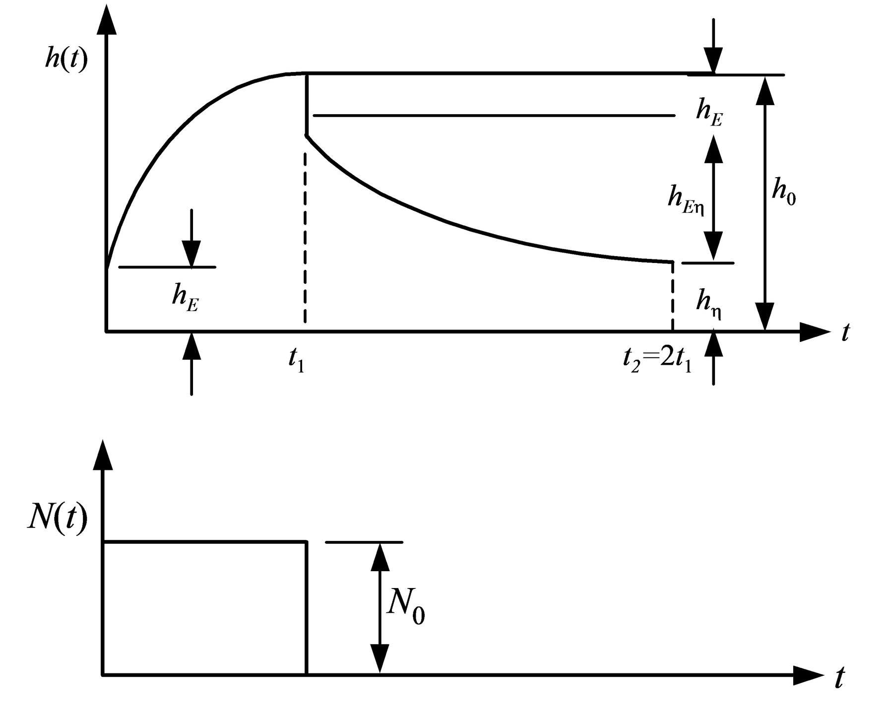
When only the initial or instantaneous elastic part of the deformation, hE, will appear. It follows from Equation (8) that:
(9)
Final Steady State Deformation
When sufficient time has elapsed for all three elements of the deformation, elastic, viscoelastic and viscous, to appear. In Equation (8) the term becomes small very rapidly as t/τi becomes large, and is considered negligible for t/τi > 7.
Then, for time t = t1 in Equation (8) the following expression is obtained:
(10)
where hEη is the viscoelastic part of the impression depth and hη(t1) is the linear, time-dependent viscous part of the impression depth.
The function h(t), for both loading and unloading of the ball can be used to determine the total ball impression depths, that is, h0, hE, hEη and hη, and thus also some rheological characteristics. The form of the characteristic is shown in Figure 1.
Differentiating Equation (10) with respect to t1:
Since hη(t) is linear, it follows that:
and after substitution and rearranging:
(11)
From Equations (9), (10), (11) the rheological characteristics of the solid propellant can be determined.
In particular, Equation (9) gives:
(12a)
which is the instantaneous modulus of elasticity, Equation (11) gives:
(12b)
which is the viscosity of the viscous element of the model, and Equation (10) gives:
(12c)
which is a measure of the total deformation per unit load after a loading time t1.
The contribution, i, made by each of the three elements to the total deformation can also be determined and expressed as a proportion. Equations (9) and (10) give:
(13a)
Equations (10) and (11) give:
(13b)
and
(13c)
The total compliance of the elastic and viscoelastic elements of the model is:
and the estimated long-time (total) modulus of elasticity of the elastic and viscoelastic elements is:
(14)
and these are important mechanical characteristics of solid propellants.
Viscoelastic Deformation and Creep Index, κ
The evaluation of the time-dependent viscoelastic deformation for gives significant information about the rheological properties and structure of solid propellants. The calculation can be simplified if the time history of the impression depth h(t) is approximated by a simple power law:
(15)
which, on a log-log plot, represents a straight line of slope κ. This slope or creep index, κ, is an important rheological characteristic, especially if its relationship to the load on the ball, κ(N), and to the natural or artificial aging of the material, are both known. The latter is particularly important since it is a very appropriate measure and one for which there is no suitable alternative available from other destructive tests [8].
Conventional Characteristics
The above characteristics can be supplemented by two standard methods, namely,
Brinell hardness - the ratio of the load to the ball impression area.
(16)
This test can be modified to give the impression depth as a function of time, h(t).
Mayer hardness [4, 5] - the ratio of the load to the projected area of the ball impression.
(17)
This characteristic can be used to advantage to determine the mechanical properties of solid propellants since it is related directly to its ultimate strength, and to some other characteristics. The test conditions are the same as those of the Brinell test.
The tests also enable the so-called elasticity, defined as:
(18)
to be determined, which gives the elastic deformation, both instantaneous and delayed, as a proportion of the total deformation. Similarly, the plasticity can be determined from:
(19)
The above derived and conventional characteristics are summarised in Table 1.
Test Results
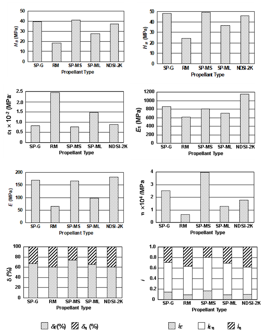
Using the methodology described, the characteristics of the following solid propellants have been determined.
SP - G (for RM 70 122 mm)
RM (Rocket Mass – double base diglycol)
SP - MS (Ng powder for SM ATGM 9Ml4M)
SP - ML (Ng powder for LM ATGM 9Ml4M)
NDSI - 2K (for RPG 15)
A prototype CREEP test equipment [14] was used for the experiments with a propellant temperature of 21 to 22 °C and a ball diameter of 5 mm. The results are listed in Table 2 and shown graphically in Figure 2.
Conclusions
The tests described and the results for a number of solid propellants and other combustible materials have been used to advantage during development, and for evaluation of mechanical properties after aging.
It has been shown [14] that the characteristics examined correlate well with those obtained from other tests, such as tension, pressure, impact strength, and the classical Brinell test. At the same time the results of the modified Brinell test offer a complex picture of the rheologic characteristics of solid propellants which cannot be achieved by other means.
| Serial | Characteristic | Units | Eq No | Application |
|---|---|---|---|---|
| 1 | Hardness by Brinell HB | MPa | 16 | Prediction of compression strength Rmd |
| 2 | Hardness by Mayer HM | MPa | 17 | Prediction of tensile strength Rmt |
| 3 | Measure of deformation per unit load 1 | MPa-1 | 12c | Prediction of rigidity and fraction limit |
| 4 | Instantaneous modulus of elasticity E1 | MPa | 12a | Indicates instantaneous rigidity (Young's modulus) |
| 5 | Total modulus of elasticity E | MPa | 14 | Indicates long-term rigidity |
| 6 | Conventional viscosity | MPa s | 12b | Prediction of material creep – for manufacturing techniques and long-term storage |
| 7 | Proportion of elastic component iE | 13a | Proportion of elastic deformation component –for improving manufacturing techniques | |
| 8 | Proportion of plastic component i | 13b | Proportion of plastic deformation component –for improving manufacturing techniques | |
| 9 | Proportion of visco-elastic component iE | 13c | Proportion of visco-elastic deformation component –for improving manufacturing techniques | |
| 10 | Elasticity E | % | 18 | As Serial 7 |
| 11 | Plasticity | % | 19 | As Serials 8 and 9 |
| 12 | Index of creep | 15 | Time dependent behaviour of visco-elastic deformation- for evaluation of solid propellant aging |
| Serial | Characteristic | Propellant Type | ||||
|---|---|---|---|---|---|---|
| SP-G | RM | SP-SM | SP-ML | NDSI-2K | ||
| 1 | HB (Mpa) | 39.3 | 18.2 | 41.1 | 27.6 | 37.2 |
| 2 | HM (MPa) | 47.7 | 24.0 | 49.3 | 36.6 | 45.6 |
| 3 | 1 10-2 (MPa-1) | 0.8291 | 2.451 | 0.7561 | 1.490 | 0.8933 |
| 4 | E1 (MPa) | 858.8 | 616.8 | 798.4 | 706.7 | 1144.6 |
| 5 | E (MPa) | 169.4 | 65.3 | 165.2 | 97.5 | 180.7 |
| 6 | 104 (MPa s) | 2.5141 | 0.6527 | 3.9736 | 1.2906 | 1.7672 |
| 7 | iE | 0.14 | 0.09 | 0.17 | 0.09 | 0.10 |
| 8 | i | 0.29 | 0.37 | 0.20 | 0.31 | 0.38 |
| 9 | iE | 0.57 | 0.54 | 0.63 | 0.60 | 0.52 |
| 10 | E (%) | 66.7 | 60.0 | 73.9 | 64.9 | 60.0 |
| 11 | (%) | 33.3 | 40.0 | 26.1 | 35.1 | 40.0 |
| 12 | 0.09749 | 0.16158 | 0.08831 | 0.11673 | 0.16320 | |
| r | 0.9913 | 0.9905 | 0.9844 | 0.9952 | 0.9895 |
References
[1] V. Gromov, “Contact Task of Viscoelasticity with Movable Limit”, Strength and Plasticity, Nauka, Moscow, pp. 203 – 207, 1971.
[2] D. Bland. The Theory of Linear Viscoelasticity, 1960, Russian translation, Mir, Moscow, pp. 115 – 118, 1965.
[3] V. Moskvitin. Strength of Viscoelastic Materials (For Solid Propellant Rocket Engines), Nauka, Moscow, 1972.
[4] S. Ajnbinder and M. Laka, “Hardness of Polymer Materials”, Mechanics of Polymers, Vol. 3, pp. 337 – 349, 1966.
[5] S. Ajnbinder and A. Loginova. “Hardness of Fibreglass”, Mechanics of Polymers, Vol. 4, pp. 616 – 620, 1969.
[6] D. Polipenak and P. Melentjev, “Relationship between Brinell Number and Modulus of Elasticity for some Thermoplastic Polymers”, Mechanics of Polymers, Vol. 3, pp. 153 – 155, 1965.
[7] M. Martirosjan, “Effect of Aging on Creep of Glassfibre SVAM during Loading for Different Fibre Directions”, Mechanics of Polymers, Vol. 6, pp. 20 – 29, 1965.
[8] A. Nikolskoj, I. Kuznecova and G. Tatevosjan, “On the Aging of Plastics by Non-Destructive Testing Using Mechanical Tests”, Plastics, Vol. 1, pp. 52 - 57, 1968.
[9] Ju. M. Molcanov, Physical and Mechanical Properties of Polyethylene, Polypropylene and Polyisobutylene, Zinatne, Riga, pp. 47 – 49, 1966.
[10] L. Lebedev, Machinery and Devices for Testing Polymers, Mašinostrojenije, Moscow, pp. 164 – 181, 1967.
[11] A. Je. Omeljanov, “Machinery and Devices for Testing Polymers”, Plastics, Vol. 6, pp. 51 – 55, 1963.
[12] B. Plíhal, Methods for the Examination of Rheological Characteristics of Solid Propellant, [Professorial Thesis], Military Academy in Brno, Brno, pp. 70 – 87, 1991.
[13] N. Bezuchov, Introduction to the Theory of Elasticity, Plasticity and Creep, Vyssaja Skola, Moscow, 1968.
[14] B. Plihal, Mechanical Properties of Solid Propellant, [Research Report], Military Research Institute 011, Slavicín, 1983.