
Volume 3, Number 2, July 2000
Modelling Of The Vulnerability Of Tanks And Other Protection Systems
Abstract
This paper presents a gun-target line based vulnerability modelling of tanks or other vehicle targets in Finite-(triangle-)Element representation by use of MSC/Mentat. Penetration and residual energies are estimated by an appropriate penetration formula. Target vulnerability is evaluated by kill-probabilities in accordance with four probability cases: mobility kill, firepower kill, personnel kill, and catastrophic (total) kill, with emphasis to personnel kill with additional protection by fibrous armour and the effect of different armour. Experimental results support the overall validity of the simulation approach applied.
Introduction
Vulnerability modelling of exposed hulls, devices or personnel has emerged as a versatile improvement tool for matching desired survivability levels and necessary protective measures under tight resource allocation regimes.
Based on a Finite-(triangle-)Element target model and a ballistically sufficiently described gunning device including geometrical arrangement data of these elements, a gun-target line taking into account projectile deflection and spallation at target incidence is established.
In the calculations the projectile hits the armour with a given velocity and direction. Using the de Marre penetration formula [1] (any other appropriate formula or numerical data could also be used), the residual kinetic energy of the projectile after penetration is estimated. The penetrating projectile and spallation fragments give rise to damage to inner target components and personnel. These damage effects are evaluated via kill-probabilities in accordance with four kill-probability cases: mobility kill, firepower kill, personnel kill, and catastrophic (total) kill.
This paper aims to emphasise the applicability of the proposed simplified vulnerability evaluation procedure to real world situations and, in addition, to demonstrate its inherent potential for tailored (composite) armour distribution improvements for tanks and other vehicles or devices to give optimised protection levels and acceptable ratios of armour to total vehicle or device weight.
This project was realized in a cooperation of the University of Vienna, the Military Technology Agency and the company Steyr DaimlerPuch Spezialfahrzeuge AG & Co KG.
Simulation modelling
In the literature many different models of vulnerability shots have been discussed [2-9]. To obtain the total vulnerability of any device we have to combine several procedures. For complete modelling we need information on the device, the weapon, material properties of the armour and the vulnerabilities of the components and personnel. These elements are discussed in the following sections.
Vehicle model
The vehicle model is formed with triangles by using the pre- and post-processor program MSC/Mentat of a Finite-Element program (MSC/Marc). The triangles are described by their co-ordinates and the connectivities between the co-ordinates. In this paper the triangles are called elements, because of their origin from the FE-analysis.
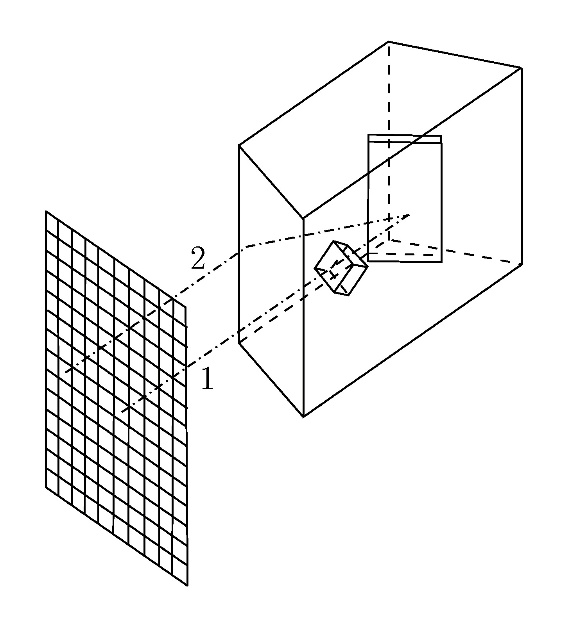
This vehicle model can also be read directly from a CAD-iges-file and then modified according to the requirements of our program, which means that the least possible number of triangles is needed. This is essential, because the algorithm for finding the elements crossed by the gun-target line takes a time proportional to N2, N being the number of triangles. We performed this task with the vehicle model of Figure 2.
Shot model
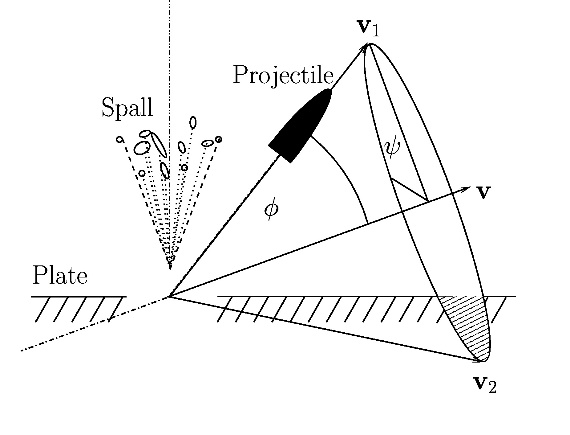
This model determined how the projectile is deflected from its direction and how the spallation particles are dispersed within a defined region. As illustrated in Figure 1, a projectile hits a plate and is deflected. The spallation particles originate from the material of the plate.
The penetrating projectile is deflected into a direction given by φ and ψ. φ is normally distributed, ψ evenly distributed. All vectors with the same ψ (on the cone shown) have equal probability (for example, v1 and v2). All vectors for which v points into the plate (v2) are discarded.
In the first step, the direction of the shot is given by two angles, defining a unit vector v in the direction of the shot. If a range of angles is given, the vector is a sample from the equal distribution on a sphere by use of the algorithm of Marsaglia [10], which is then restricted to the given area.
As illustrated in Figure 2, a virtual plane normal to the shot-vector is then divided into squares. Figure 2 shows an arrangement of six plates, which first is used to demonstrate the effect of deflection and investigate the number of trials necessary for good results. The shots originate from the -x-direction and the plate not normal to the gun-target line causes spallation, which damages the inner target components for shots coming from the left (gun-target line 2). This happens because the spallation particles are deflected from the normal vector of the plate not from the shot direction like the projectile. Gun-target line 1 shows that the small cube protects part of the bigger object.
The resolution of squares is selectable and we set it to the usual value of 10×10cm2 in our calculations. Into the centre each of these squares a shot-vector is placed and the sequence of penetrated elements is calculated by means of Gaussian elimination with partial pivoting [10]. The angles, distances and thickness of the components of the armoured vehicle are also evaluated. After each penetration of a component, the deflections of the projectile and of the spallations are computed by Monte Carlo methods.
Deflection of the projectile and the spallation particles
We assume the deflection of the projectile to be normally distributed. Further details can be found in Figure 1. If the projectile is deflected backwards from the plate, the sample from the distributions of the angles φ and ψ is repeated until the deflection is forward. This leads statistically to a deflection of the shot away from the plate into the direction normal to the plate.
Spallation-particles are calculated in a similar way. The only difference is that the vector of zero deflection is the normal vector to the plate.
Ballistic limit
At the ballistic limit the thickness of the plate d (in dm) can be obtained from the penetration formula of de Marre [1]:
(1)
where m is the mass in kg and c the calibre of the projectile in dm, v the velocity at the time of impact in m/s, and γ the obliquity in degrees measured from the normal, and A is an empirical factor. If for a given projectile the thickness of the plate d' is smaller than d the projectile perforates the plate with a residual velocity.
This formula uses the following assumptions. The energy of the impacting projectile is used up by deformation and friction, characterised by the empirical constant A, which depends on material properties. The thickness d at the ballistic limit is achieved when no energy is left and the projectile is stopped.
One can calculate A from experimental evaluation of the thickness d, the ballistic limit v and the dimensions of the projectile.
Total energy
The total energy of the projectile and the spallation particles after the penetration can be calculated from Equation (1). It can be calculated in the following way: by rearranging Equation (1) we obtain:
(2)
The maximum energy not to penetrate the plate of thickness d is obtained by Equation (2). The difference of the energy Ed to the actual energy of the projectile E0 is the energy ER, which the penetrating projectile and the spallation particles carry with them. Thus:
(3)
This is an estimate of the residual energy with which the projectile and the spallation particles hit the inner components of the vehicle. This energy is assumed to be entirely translational, that is rotational energy is ignored.
Energy division
This energy is divided between projectile and spallation particles according to the following rule. The residual energy ER is the sum of the energy of all spallation particles Es and the energy of the projectile Ep.
(4)
with E0 being the impact energy of the projectile at impact on the hull. The n spallation particles have energy Es /n each. We chose this form of energy distribution for the following reasons. If the projectile has not enough energy, it will not penetrate and there will only be spall, if the projectile has much energy, the spall will have a lesser fraction of energy. n is calculated from an equal distribution between a minimal and a maximal value of spallation particles.
Damage of each component
The damage of each component is determined by comparing the residual energy to the energy needed to destroy the component. If the residual energy is greater than this energy, the component is killed. The problem of different vulnerabilities of one component is approached by dividing the surface of the component in areas of different damage energies, such as an engine with aluminium parts, rubber hoses, and so on. If a projectile or spallation particle has the energy to destroy a part of the component, the probability for this projectile or spall particle to destroy the whole component is given by the ratio of the area of this part to the area of the component.
Example: consider the vulnerability of a human. In [11] the vulnerability of a human is considered to lie between 79J and 90J. In our calculations we consider 50% probability with 79J and 50% with 90J. One could, for instance, choose some very low percentage of a much lower value of energy to model the vulnerability of the eyes. We also consider some body armour, which gives more protection.
Evaluation
These binary results (damaged versus not damaged) are statistically evaluated over a sufficient large number of trials and analysed according to their kill-probability case. These kill-probability cases are personnel-, mobility-, firepower- and catastrophic-kill [2]. The results can be viewed as a list of numbers or as a coloured picture with MSC/Mentat. Only the damage criteria of the vehicle itself is determined. To determine the effect of a weapon in the battlefield the distribution of different shots (hit or miss), or even different weapons, must additionally be included. This would require repeated runs of the program to determine the overall probabilities. This has not been done in this work since our emphasis is on the vulnerability and improvement of one vehicle.
Obviously a direct verification of the results of the computer code is both difficult and extremely expensive. Empirical validation of single components is done all over the world but is not available in the open literature.
Computations
For the demonstration of the capabilities of the computer code with respect to the various kill-properties we use a .50 inch calibre machine-gun. Values for the parameter A in Equation (1) were chosen for two cases: such that the projectile penetrates easily (value A1), and such that it barely penetrates (value A2). Values for A in various materials can be found in [1].
- A model of 6 plates surrounding two simple objects (see Figure 2). The projectile penetrates through the plates: the small object has a penetration thickness of two-fifths of the surrounding plates and the bigger object has the vulnerability of a human. We make calculations:
- without considering deflections of projectiles and spallation particles; and
- with deflections, where the angles are normal distributed and the normal distributions have =20 for the projectile and =40 for the spallation and only one spallation particle per shot.
The results are shown in Figure 3. The two pictures show a shot without deflection (a) and with deflection (b). The vertical line in the left picture (a) corresponds to the spallation particles, which are deflected normal to the plate, and the right part of damage is caused by the projectile. The hole in this part is caused by the small cube, which protects the other body from being damaged. Probability zero is grey, probability 1 is black.
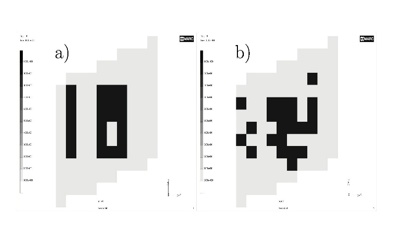
Because the plate is not perpendicular to the gun-target line the damage of the inner components occurs in two different areas, one coming from the spallation particles, one from the projectile. The area damaged by the projectile has a region of no damage, where the small cube protects the bigger object, because the projectile is stopped (see Figure 2).
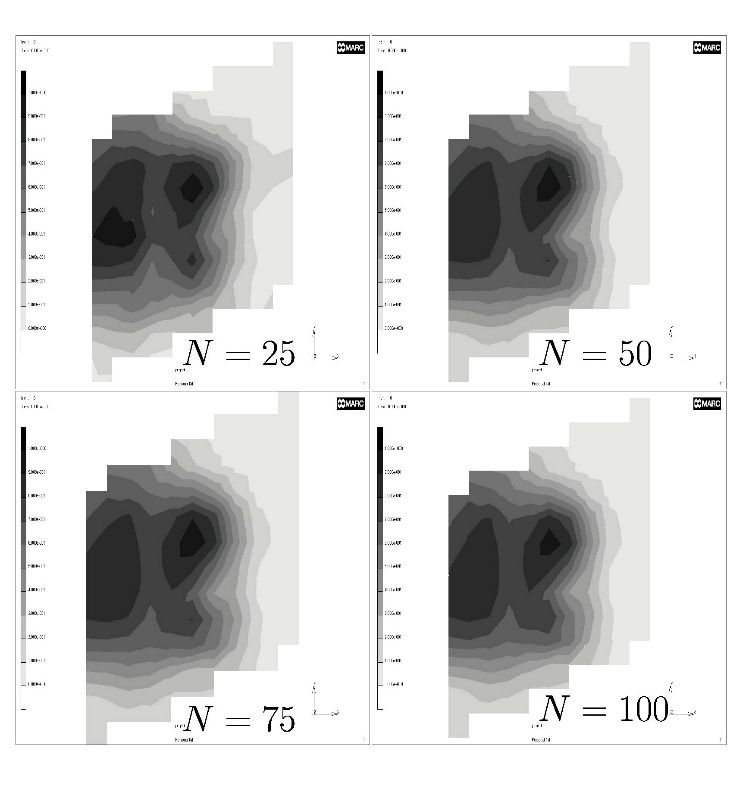
- The second investigation concerns the number of shot trials necessary to get representative results. We chose the number of trials to be 25, 50, 75 and 100. The kill probability is given in Figure 4 as shades of grey. Pictures of N=25, 50, 75 and 100 trials show, that good results can already be achieved with 50 trials, but 75 to 100 would be better. In this calculation the number of spallation particles lies between 3 and 10. Probabilities from zero (grey) to 1 (black).
- After investigating a large number of plots we concluded that acceptable results can be achieved with only 20-50 trials. Best results need 75-100 trials. The number of trials is considered sufficient if more trials give no different result. In some sensitive areas 150 trial-shots are needed. If no interpolation algorithm for data-presentation is used such as with MSC/Mentat, many more shots could be necessary for statistically significant results. Figure 4 also shows the two regions of damage and the small region of protection caused by the small cube.
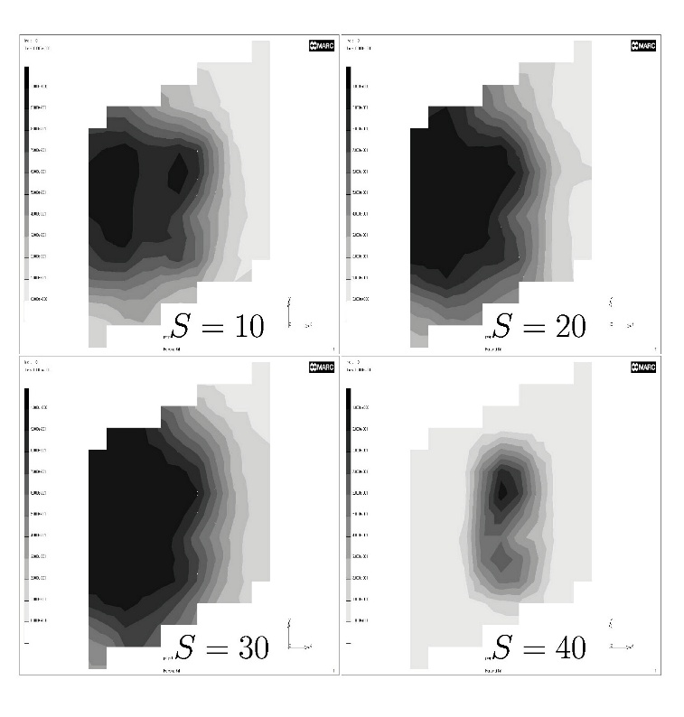
- We also consider the effect of the number of spallation particles. Figure 5 shows that, with increasing number of spall particles, n, the region of damage increases, until the energy of one spall particle Es /n becomes too small and only the projectile influences the result. Pictures of 50 trial-shots with n=10, 20, 30 and 40 spallation-particles, which first give two regions; one where the projectile damage dominates, and one where the spallation damage leads. When the number of particles increases, these two regions combine to one region. And with even more spallation-particles, the energy per particle is too small for damage, thus only the projectile leads to an effect.
While the model with six plates illustrates the effects, a model closer to practical applicability has been chosen for the calculations shown in Figures 7 and 8. A simple armoured-vehicle-like object shown in Figure 6 was assumed. We arbitrarily choose two different materials, one with A=A1, and a better one with A=A2. The thickness of the front plate is chosen in a way, that the better material stops a shot of the machine gun fired from the front. The shot penetrates the weaker plate. The vehicle turret is armoured in such a way that a shot is stopped when A=A2 and not stopped with A=A1 at an obliquity of approximately 48°.
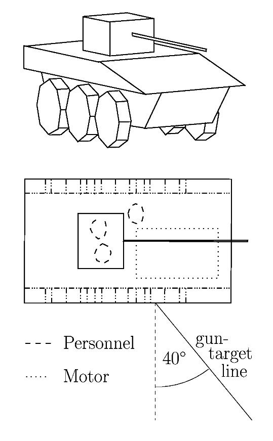
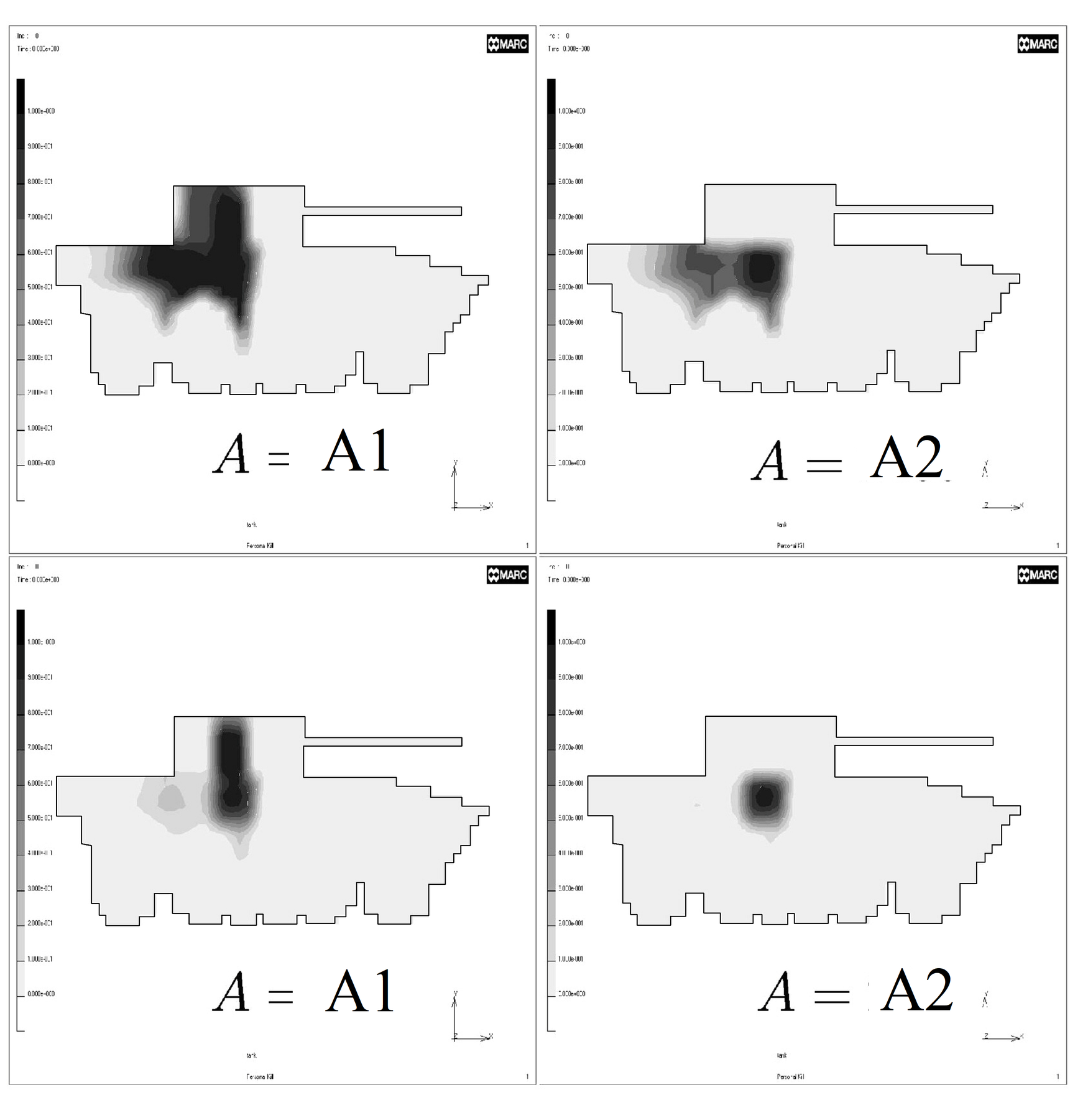
For shots from the front and an obliquity of 40° the results for the two assumed armours are shown in Figure 7. We calculated 150 trial shots. The upper pictures show unprotected personnel and the lower picture personnel protected by fibrous armour to 90% of their body-surface. Probability-range zero (grey) to 1 (black). The turret of the better-armoured vehicle shows no kills. The driver and the commander are protected completely by the front plate and the engine. The other kill values show the better protection of the armour with A=A2. The left part of the damage in the pictures of Figure 7 again represents the effects of the spallation particles; the right part represents the effects of the projectile. This figure also shows the protective features of the engine and the rubber tyres.
Below, the same scenario with the personnel additionally protected by fibrous armour [12], which has a protective feature of 300J and covers 90% of the body. The damages from the spallation particles reduce in both cases, in the case of A=A2 to values below 0.1.
In the case of a shot directly from the side, the differences of the two vehicles are minor. The projectile or the spallation particles have sufficient energy for damage in any occasion.
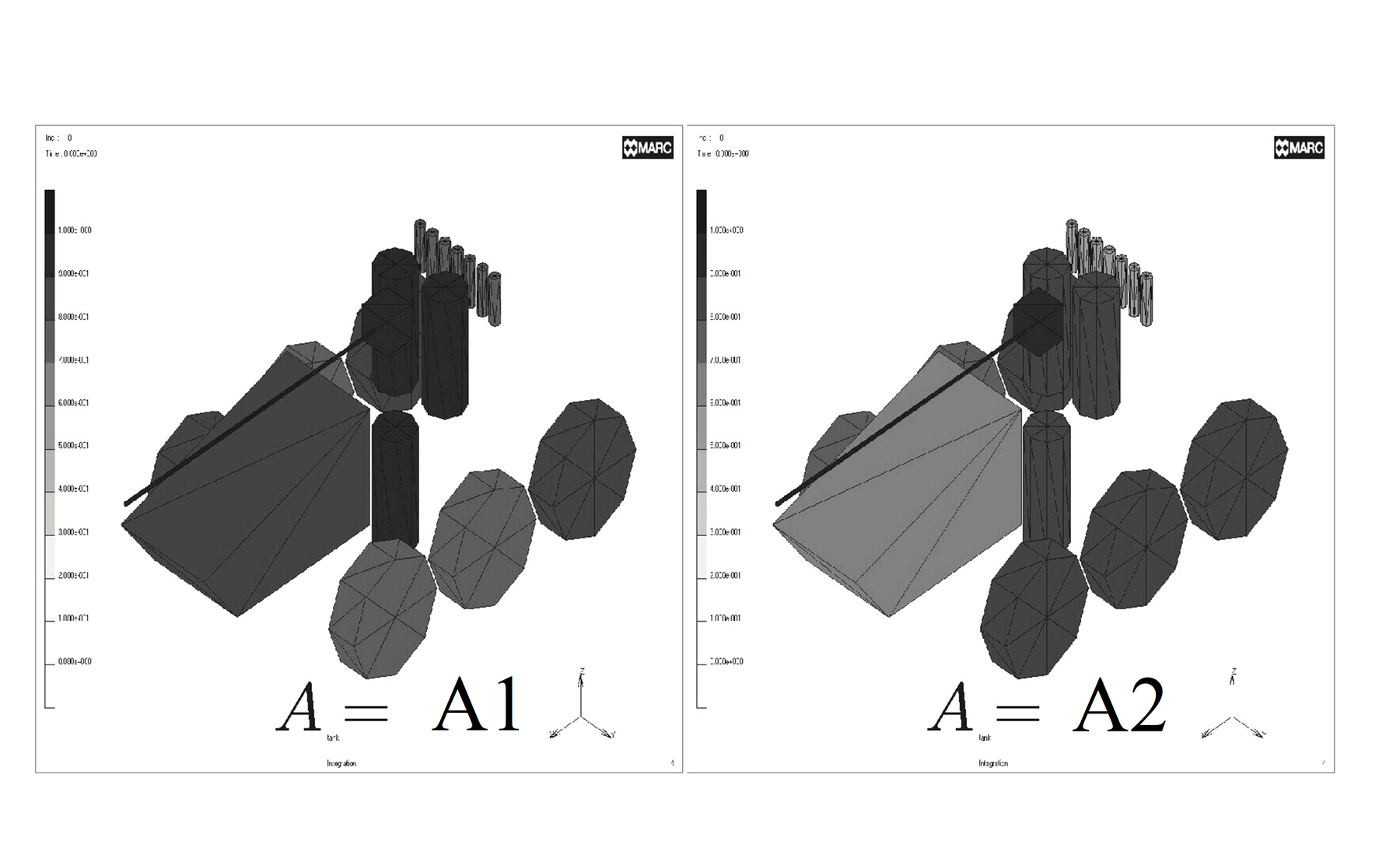
Finally the vulnerability for shots for all directions has been evaluated for the model of the vehicle (similar to [5]): Shots come from all directions, equally distributed in the full solid angle. Damage is determined as above. Damage values are obtained for the inner components of the vehicle. Results are shown in Figure 8. The better armour gives more overall protection.
Figure 7. Personnel-kill probability distribution of the vehicle with two different armours with A=A1 in the left pictures and A=A2 in the right pictures. Probability-range zero (grey) to 1 (black).
Figure 8. Integration over a number of 1000 trials. Only the inner components and their kill-probabilities of the vehicle are shown. The vehicle with A=A2 on the right side shows more protection, induced by better armour. Probability ranges from zero (grey) to 1 (black).
Summary
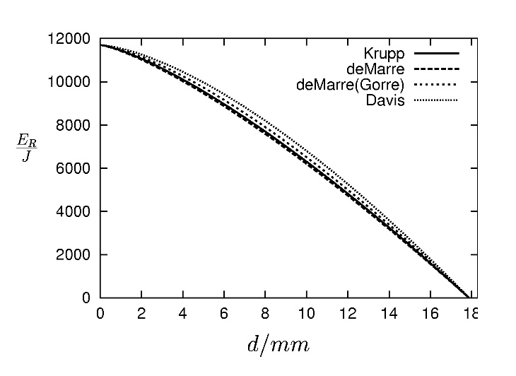
It is possible to investigate the vulnerability of tanks and other armoured vehicles and match experimental results with computer modelling. The kinetic energy of the projectile, its deviation and the spall effects are essential for the statistical examination of the value of protection with armour. The most vulnerable spot on a hull of a vehicle can be found and counter measures can be taken. Our model of spallation is simple and straightforward. It simulates just the high-energy part of the spallation-energy-spectrum. Only this part is needed for estimates. The protective features of additional fibrous body armour also can be included into the calculation and give additional safety. The use of the penetration formula of de Marre seems to be a reasonable estimate, since other formulas lead to very similar residual energies as one can see in Figure 9. Krupp 1 and 2 have an identical behaviour. Their differences lie in the different features in the treatment of different materials. The other formulas in the comparison are de Marre, de Marre (Gorre) and Davis. The differences in energy-decrease are marginal.
Because one can select each possible direction of thread, even bomblets could be calculated, if one selects the appropriate data for the penetration.
More detailed data on projectile armour interaction (if available) will improve the estimates and can easily be incorporated in the program.
In the future the features of the de Marre penetration formula should be investigated. An experimental examination of the effect of gunfire on the inner components of the vehicle would give better insights and more reasonable results with our vulnerability model. The computer program also needs to be extended to examine the protective features of an armoured vehicle on the battlefield by considering the properties of the gun. Also a calculation of armour properties against shaped charges is intended and straightforward to include.
Acknowledgments
We gratefully acknowledge the financial and technical support by the company Steyr Daimler Puch Spezialfahrzeuge AG & Co KG and the technical support from the Military Technology Agency.
References
[1] Rheinmetall GmbH, Waffentechnisches Taschenbuch, Brönners Druckerei Breidenstein, Frankfurt, p. 512, 1980.
[2] M. W. Leeuw and L. W. M. Zuidgeest, “Battle Tank Vulnerability Modeling”, 13th International Symposium on Ballistics, VM-6/1, pp. 383-391, June 1992.
[3] J. Maassen, “Integrated Vulnerability and Weaponeering Model”, 13th International Symposium on Ballistics, VM-7/1, pp. 393-400, June 1992.
[4] P. Deitz, J. Smith, and J. Suckling, “Comparison of Field Tests with Simulations: Abrams Program Lessons Learned”. BRL-Report, BRL-MR-3814, pp. 1-19, March 1990.
[5] A. Celminš, “Accuracy of Vulnerability Integrals”, BRL-Report, BRL-TR-3084, pp. 1-32, April 1990.
[6] M. Starks, “Vulnerability Science: A Response to a Criticism of the Ballistic Research Laboratory's Vulnerability Modeling Strategy”, BRL-Report, BRL-TR-3113, 1-9, June 1990.
[7] P. Deitz and A. Ozolins, “High-Resolution Vulnerability Methods and Applications”, BRL-Report, BRL-MR-3876, 1-9, Nov 1990.
[8] M. Starks, “Assessing the Accuracy of Vulnerability Models by Comparison with Vulnerability Experiments”, BRL-Report, BRL-TR-3018, pp. 1-15, July 1989.
[9] P. Deitz and Aivars Ozolins, “Computer Simulations of the Abrams Live-Fire Field Testing”, BRL-Report, BRL-MR-3755, pp. 1-44, Oct 1988.
[10] F. Vesely, Computational Physics - An Introduction Plenum Press, New York, pp. 24 and 75, 1994.
[11] L. Xiangdong, Z. Yunfa, and W. Huizki, “A Research on the Damage Criteria of Target Components in Vulnerability Assessments”, 17. International Symposium on Ballistics, pp. 1-297, 1998.
[12] R. Laible, Ballistic Materials and Penetration Mechanics. Elsevier Scientific Publishing Company, Amsterdam - Oxford – New York, p. 73, 1980.
[13] K. Hoog, “Panzerdurchschlag und Panzerschutz”, CCG-Lehrgang Bl. 17, 1988.