
Volume 2, Number 3, November 1999
On the Stabilisation of Out-of-Balance Guns
Abstract
The current interest in mounting large calibre guns in light-weight vehicles has forced designers to re-examine conventional gun-mounting practice. It has been commonly accepted that stabilising an out-of-balance (OOB) gun on a moving platform is very difficult, or impossible, to achieve. Using a simple Main Battle Tank (MBT) elevation model, a theoretical investigation is undertaken into the effect of not having the trunnion axis aligned with the centre of gravity of the elevating mass. The effect of varying amounts of OOB on the angular motion of the gun and power requirements are examined and the improvemnts using MBT hull motion disturbance feedforward are investigated.
Nomenclature
| At(s) | Vertical acceleration at the trunnions |
| fgp, ft | Force between gun and pinion, and at trunnions |
| G | Gear ratio, drive-line |
| Id, Ig, Im | Inertia of drive, gun and motor |
| K | Gain |
| mg | Elevating mass |
| N | Gear ratio, motor to gun |
| Rp | Radius of pinion |
| s | Laplace variable |
| Td, Tm | Torque, drive and motor |
| xg | Vertical displacement of elevating mass |
| Xth, Xtp | Distance |
| yh, yt | Vertical displacement of hull and trunnions |
| ωg, ωh | Angular velocity of the gun and hull |
| θd, θg, θm | Angular rotation of the drive, gun and motor |
| η | Distance from trunnions to centre of gravity of elevating mass |
| Ωh(s) | Hull pitch rate |
Introduction
The requirement for higher performance or larger calibre guns to be mounted in lighter weight (air transportable) military vehicles causes several problems, in particular, the increased recoil energy, which has to be dissipated by the recoil system. In an attempt to keep the recoil forces (trunnion pull) to an acceptable level, a larger recoil length may be required. To accommodate this increased recoil length within the limited turret diameter requires the gun to be moved forward. Additionally, achievement of the currently required elevation and depression necessitates the centre of gravity of the elevation mass to be in front of the trunnion axis. This type of mounting is referred to as out–of-balance (OOB) in this paper. There are other possible reasons why a gun may be mounted OOB, for example to achieve more space within the turret. Therefore, the effect of OOB on the Weapon Control System (WCS) is an important issue.
The primary objective of the WCS on a Main Battle Tank (MBT) is to maximise the probability of hitting a stationary or moving target with the first round, in the shortest possible time, from a stationary or moving vehicle. The current practice of locating the centre of gravity of the elevating mass at or close to the trunnions helps to achieve this objective. It is a widely held belief that, if the centre of gravity is not aligned with the trunnion, the Stabilisation Ratio (SR) of the gun will be significantly reduced. Two quotes from the literature relating to this are:
“With this equilibrating system a complete equilibrium can only be achieved for a stationary gun on a horizontal base. If the gun is tipped on its trunnion axis on sloping ground, or, as with tank and naval guns, rocked while travelling, than additional mass forces on the center of gravity of the elevating part cause the compensation to be disrupted.
For this reason, the naval guns [and presumably tank guns] can not use an equilibrator and must place the center of gravity of the elevating part in the trunnion axis.” [1],
and
“An equilibrator can only balance an otherwise unbalanced system statically. It will be apparent that, in the dynamic state, acceleration forces act at the centre of gravity of the elevating mass, giving rise to varying moments that cannot be counteracted by a conventional equilibrator. It is for this reason that equilibrators cannot be used in stabilised systems.” [2].
The SR for an MBT is defined as:
(1)
where, ωh and ωg are the angular rates of the hull and gun respectively. In this paper the SR described in Equation (1) is only discussed qualitatively. A more detailed analysis is based on the root mean square (rms) gun angular motion, and power (relative to those from a balanced gun having hull pitch rate disturbance feedforward).
This paper develops a simple elevation model for a generic 120mm MBT main armament and uses simulation techniques to examine the effect of variation in the OOB on the motions of the gun and the power requirments. The improvements of hull motion feedforward (both rate and acceleration) on the performance of the WCS are also examined.
Elevation model
In this section, a linear single degree of freedom model of the elevation axis is developed. The model is kept simple, so that the effect of the OOB can be examined. The elevation gun model is based on that given in [3].
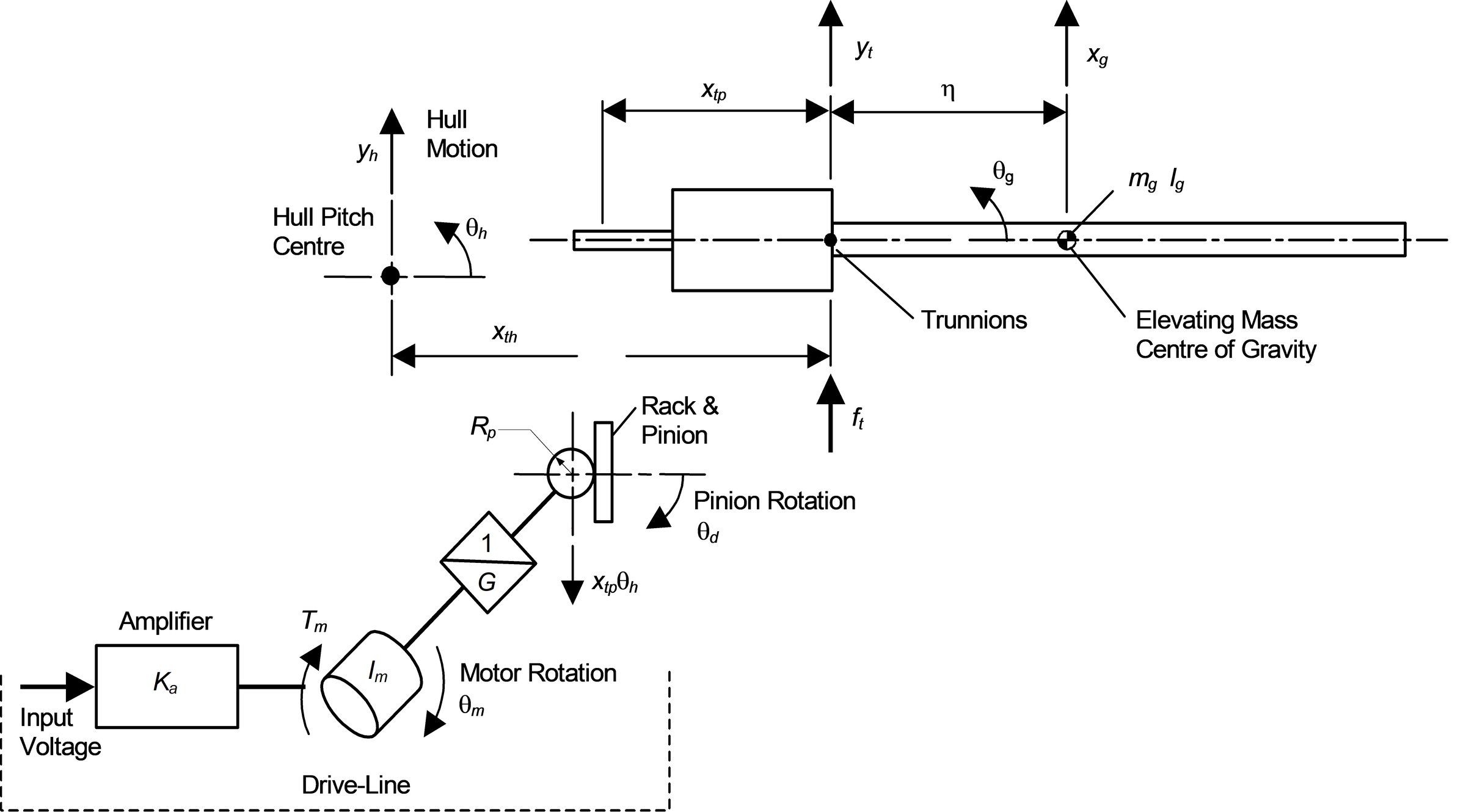
A diagram of the elevation mechanics is shown in Figure 1. The model consists of a motor, gearbox, rack and pinion, elevating mass (gun) and vehicle (represented by its pitch centre). The model is assumed to have no friction and the static balance of the gun is achieved by using an equilibrator, which is assumed to restore perfect equilibrium.
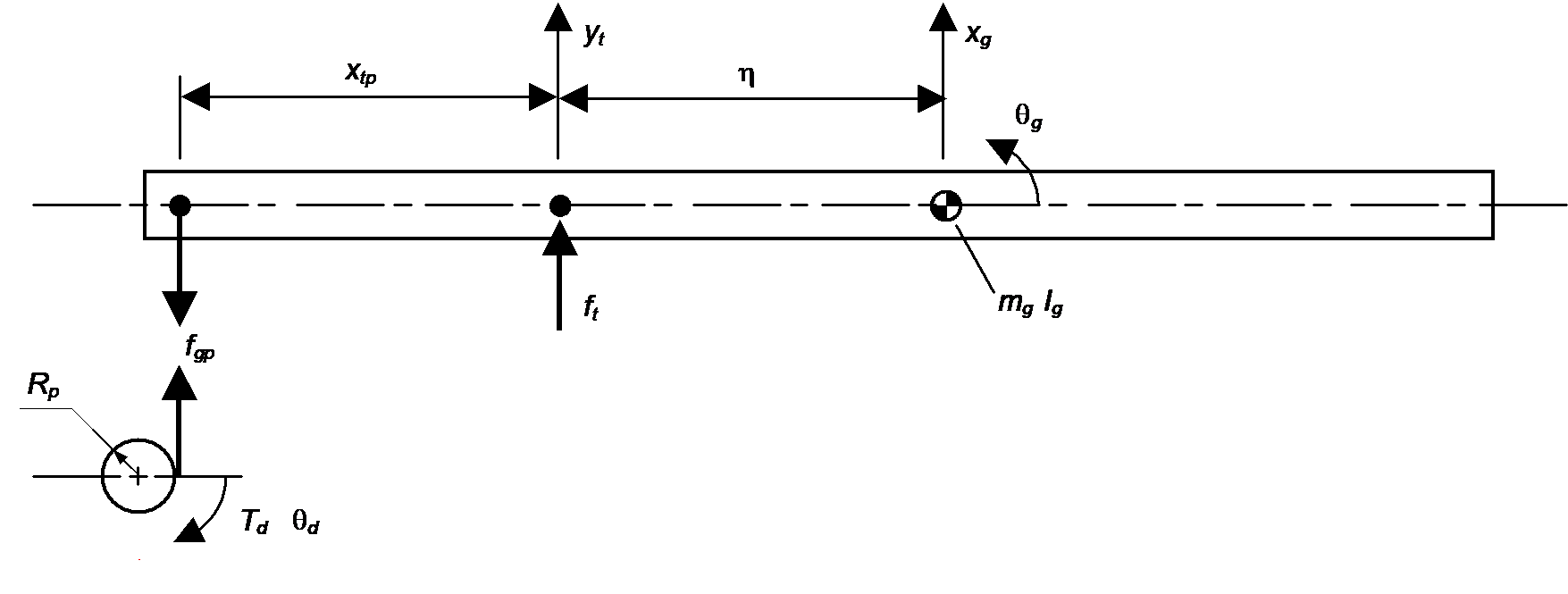
A free-body diagram for the elevation mass and drive is shown in Figure 2. The equations of motion for the system are:
(2)
and:
(3)
where, for the elevating mass, mg and Ig are the mass and moment of inertia, and η is the distance between the trunnions and the centre of gravity, and:
(4)
where for the drive, Id and Td are given by:
(5)
(6)
The kinematic constraints (Figure 1) give:
(7)
(8)
(9)
Manipulating Equations (2) to (8) and taking Laplace transforms gives:
(10)
where, Ωh(s) and At(s) are the pitch rate of the hull and vertical acceleration at the trunnions respectively, and:
(11)
(12)
(13)
where Ie is the total inertia of the system referred to the elevating mass. The transfer functions in Equation (11) can be interpreted as:
G(s) Command transfer function between the motor torque and gun rotation,
D1(s) Disturbance transfer function between the hull pitch rate and gun rotation,
D2(s) Disturbance transfer function between the trunnion vertical acceleration and gun rotation.
Effect of out-of-balance
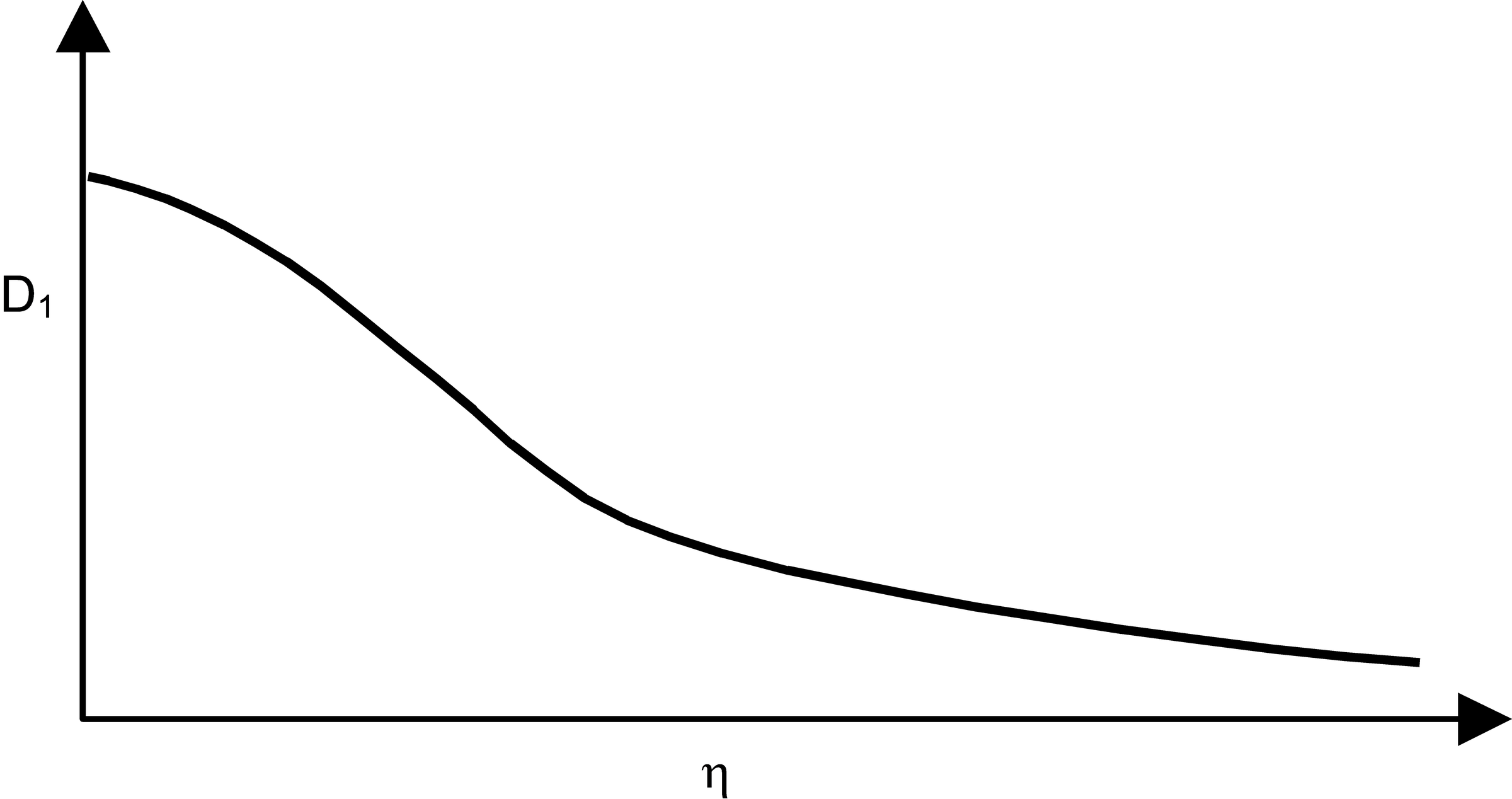
The effect of the OOB can be examined by considering the transfer functions given by D1(s) and D2(s) in Equation (11) without the Laplace variable s, defining:
(14)
The functions given in (14) are plotted in Figures 3 and 4. From Figure 3, as the OOB increases, the effect of turret pitch rate on the gun motion reduces. This is caused by the increase in total inertia and is less affected by the hull pitch motion. Thus the disturbance due to hull pitch motion is reduced as the OOB increases. As discussed in Appendix A, it is possible to eliminate the effect of the pitch motion on the gun completely.
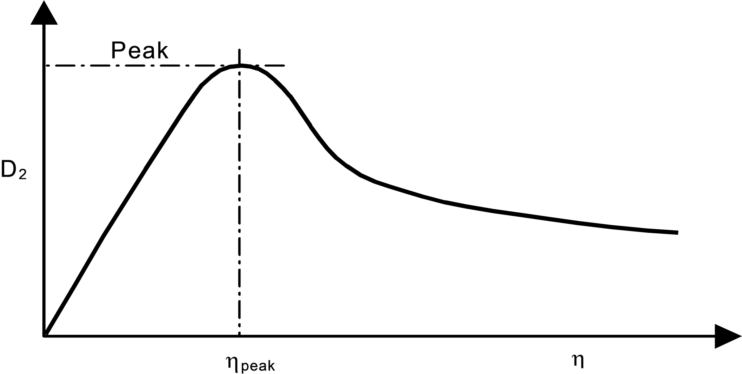
In Figure 4, coupling of trunnion vertical acceleration into gun rotation is seen to increase to a peak before reducing again. The initial slope of the plot is:
(15)
and the peak occurs at:
(16)
with a value of:
(17)
Thus the OOB causes a reduction in the SR of the gun due to the trunnion vertical acceleration. The majority of OOB gun installations fall into the initial increasing portion of this curve.
This is not the complete picture for D1(s) and D2(s) because the disturbance transfer functions are also frequency dependent, see [4] for more details.
Controller design
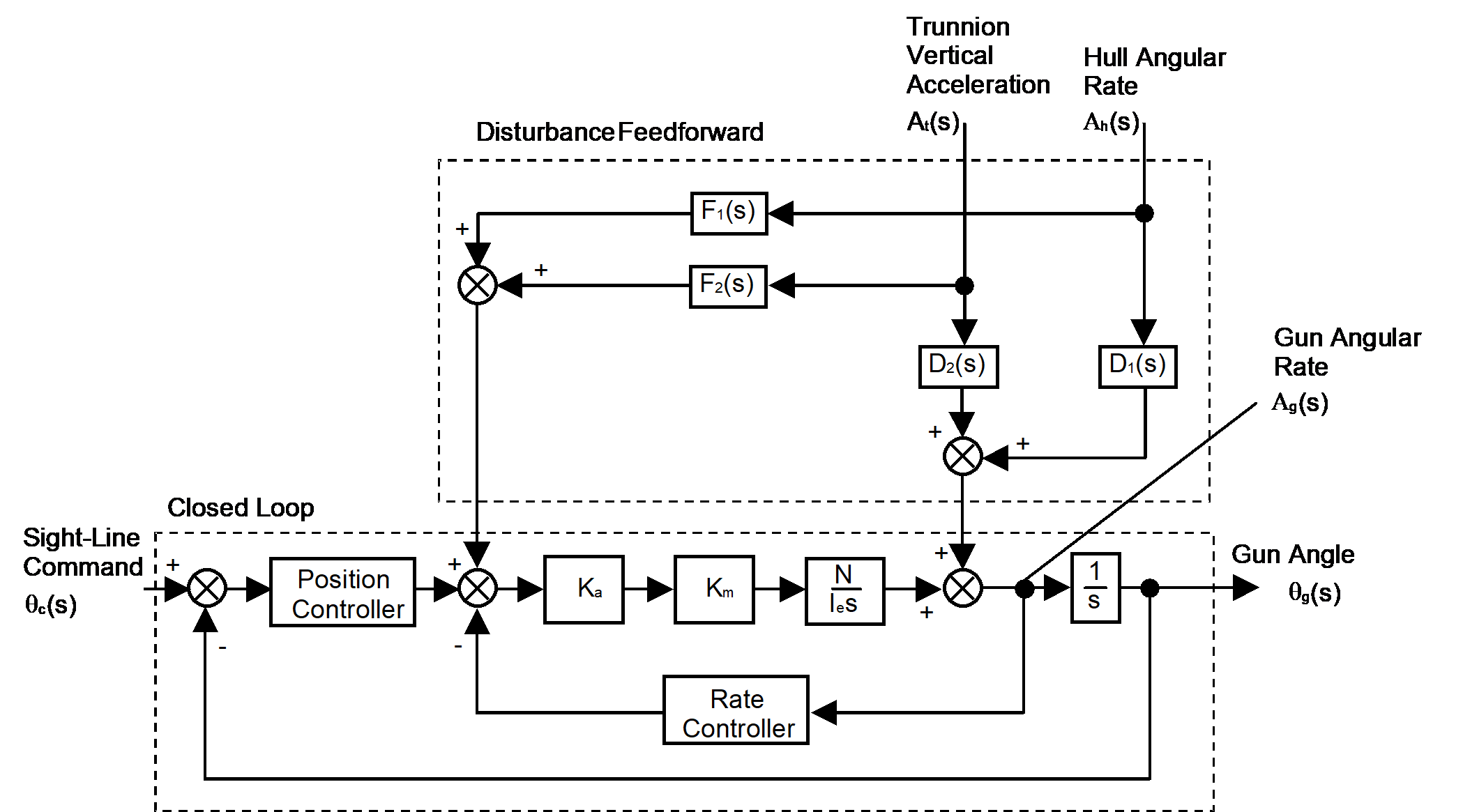
The controller has two components, for the closed-loop and disturbance feedforward. The data for the model used is given in Table 1. A diagram of the controller is shown in Figure 5.
Closed-loop controller
The closed-loop controller, Figure 5, has been designed to give a damping ratio of 0.7 and a natural frequency of 22 rad/s. With the model being second order, the closed-loop controller only requires two gains, Kv and Kp to achieve the specification. The gains Ka and Km are the amplifier and motor torque constants respectively.
Table 1. Data for the Model.
Disturbance feedforward controller
The disturbance feedforward controller has been designed following the method given in [5]. The two ideal feedforward transfer functions for hull pitch rate and trunnion vertical acceleration are given by:
(18)
(19)
because F1i(s) is an improper transfer function, it has been necessary to combine with a first order filter with a cut-off frequency of 10Hz.
Simulation results
In this investigation simulation results have been obtained for variations in the OOB and vehicle speed with the following situations:
- no disturbance feedforward,
- hull pitch rate feedforward only, and
- hull pitch rate and trunnion vertical acceleration feedforward.
The variations in OOB considered are 0 ≤ η ≤ 2.0m, which corresponds to a maximum OOB moment of 49kNm at η=2.0m. The peak value of D2 in Equation (14) is 0.35m-1 and occurs at η=1.4m. In the simulation results for the rms power, only the mechanical power has been considered.
All the results that have been presented for the rms gun angle and power, have been normalised to those with no OOB (that is, feedforward only), which has been taken as the control. The equation used for normalising was:
(20)
where Sr and Src are the rms simulation results for the case under consideration and the control respectively. Thus a value of zero represents no change with respect to the control. Plots showing the data for the control (with no OOB) are given in Figures 10 and 11, which are discussed later.
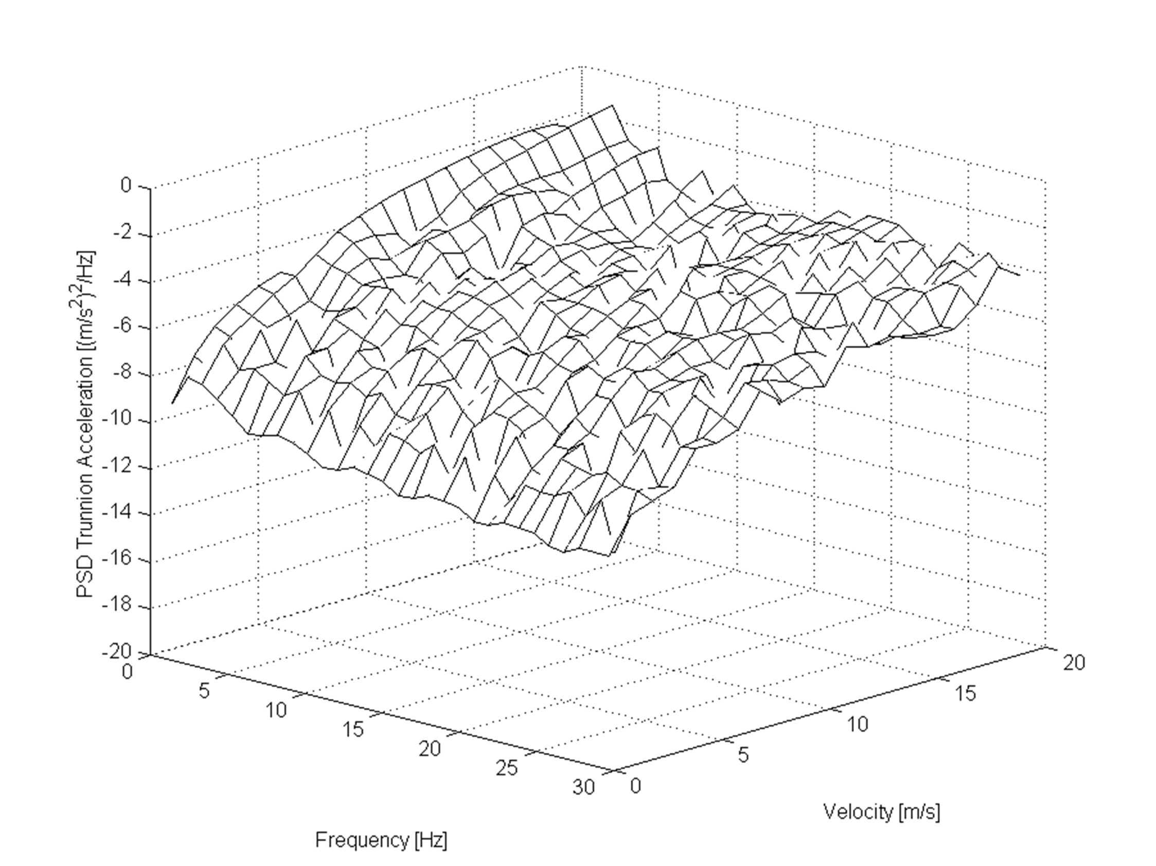
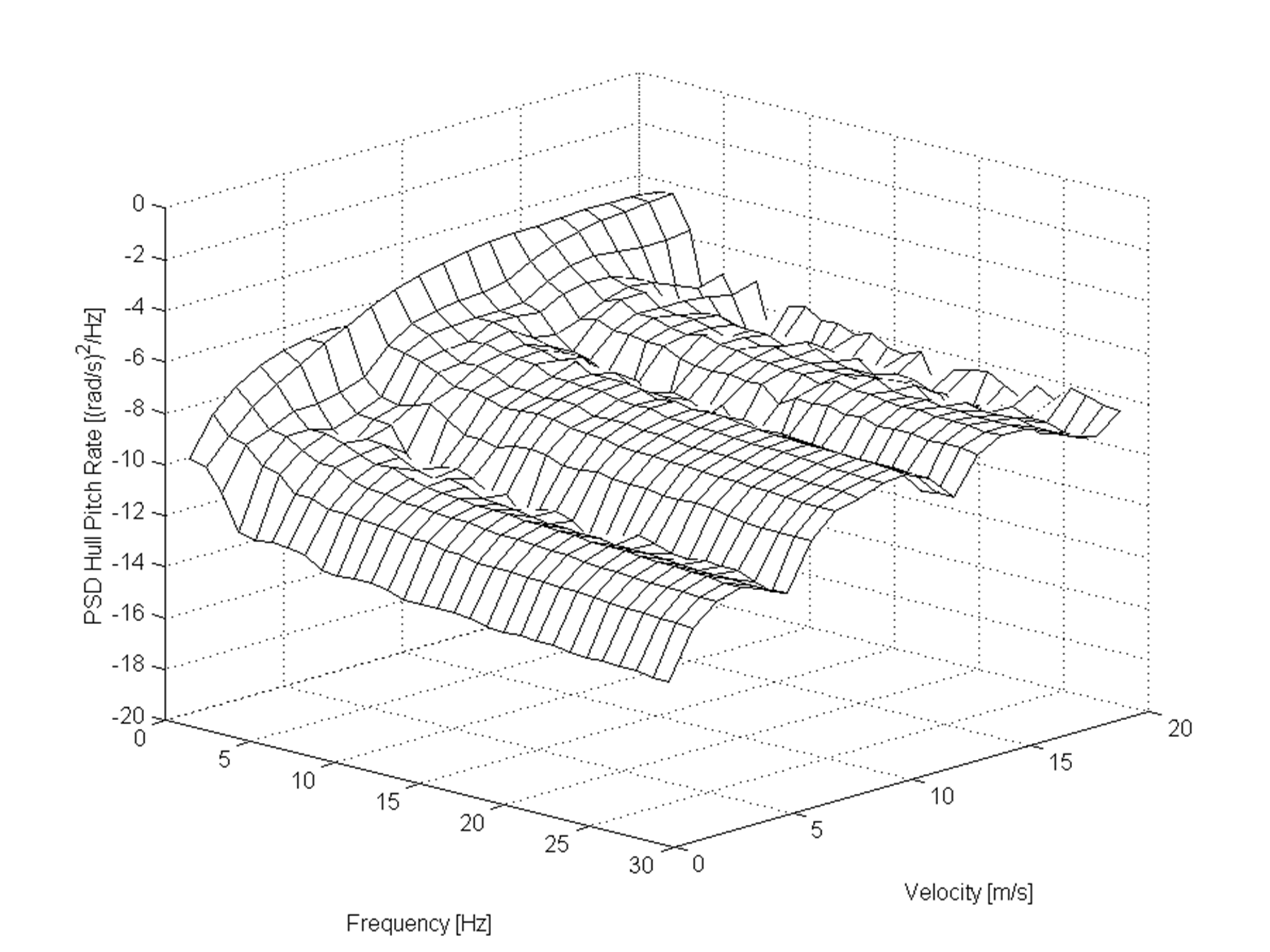
The vehicle model used has been taken from [3,6] and represents an MBT crossing random terrain. Plots showing the PSD for the hull motions are shown in Figures 14 and 15.
No hull disturbance feedforward
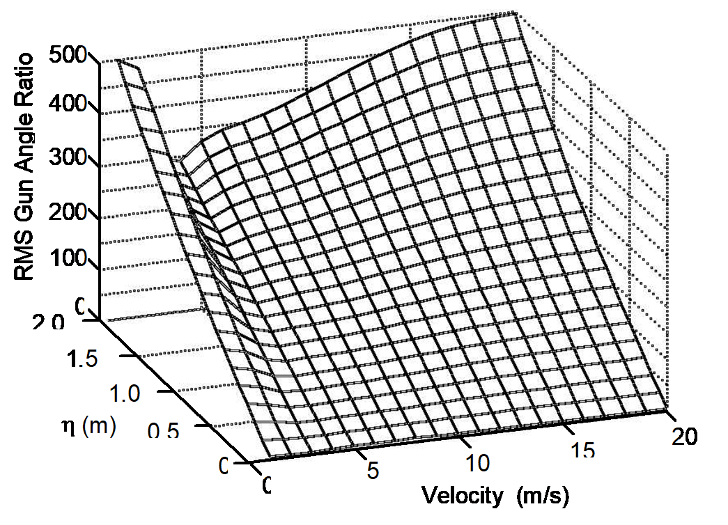
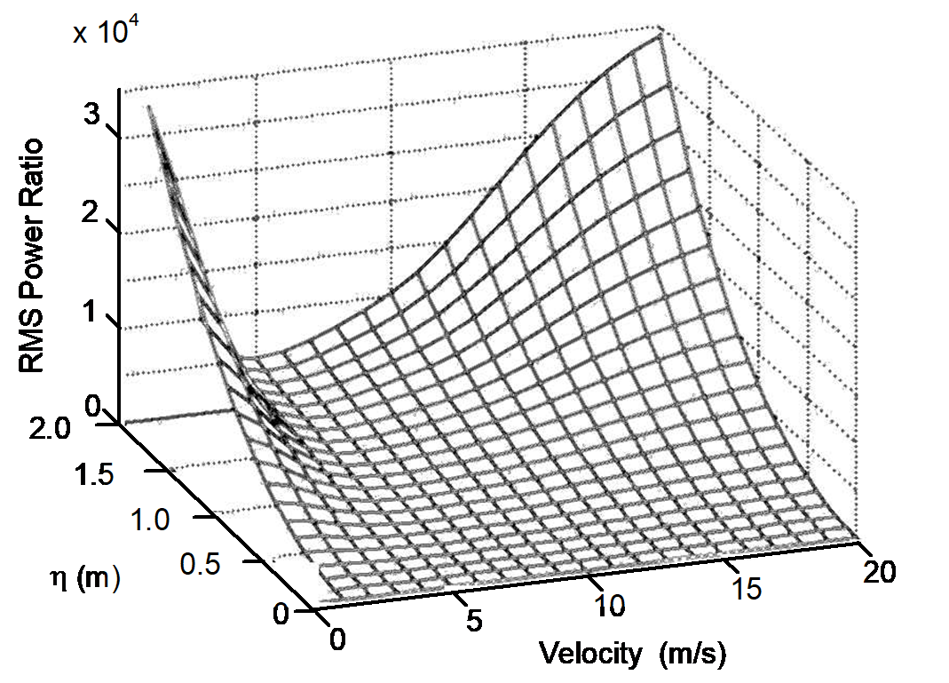
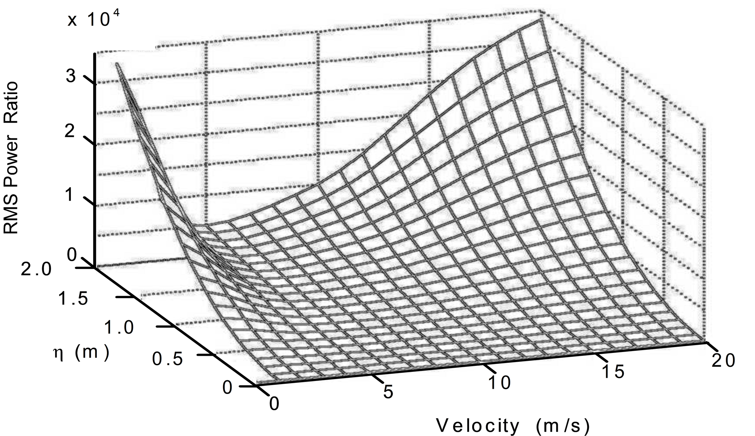
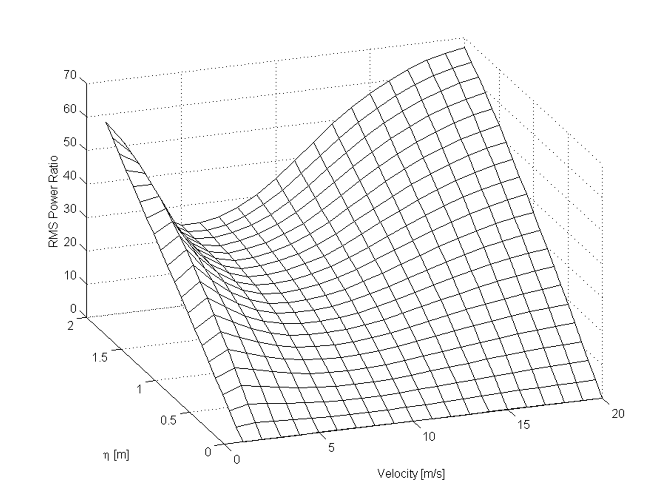
The simulation results giving the rms angular motions of the gun and power to stabilise the gun in elevation are shown in Figures 6 and 7. These plots show the effect on the gun motion and power as a function of vehicle speed and OOB (η). As the OOB increases there is a reduction in the performance of the WCS. A noticeable valley occurs in both the performance measures at a vehicle speed of between 4 and 5m/s. This may be due to the geometry of the vehicle and is discussed in more detail later. The effect on the rms gun angle shows a constant increase with OOB at each vehicle speed, reaching almost 500 times that for the control situation. Thus the coupling of the vertical acceleration of the vehicle into the gun motions can be significant, especially with large OOB mounts. For the rms power, there is a much more rapid increase with OOB at a given vehicle speed. At its maximum this shows an increase of about 35000 times. These increases in power and gun motion are due to the effects of the OOB, which were discussed in the two quotations given in the introduction [1,2].
Hull pitch rate disturbance feedforward only
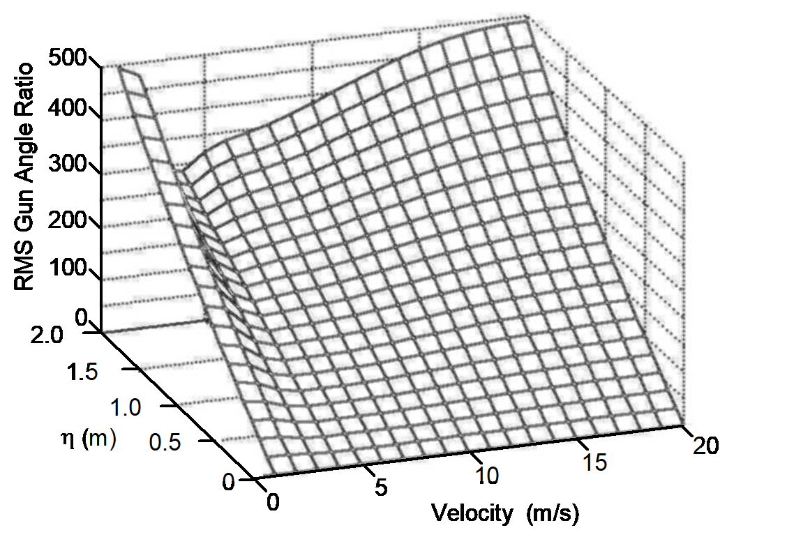
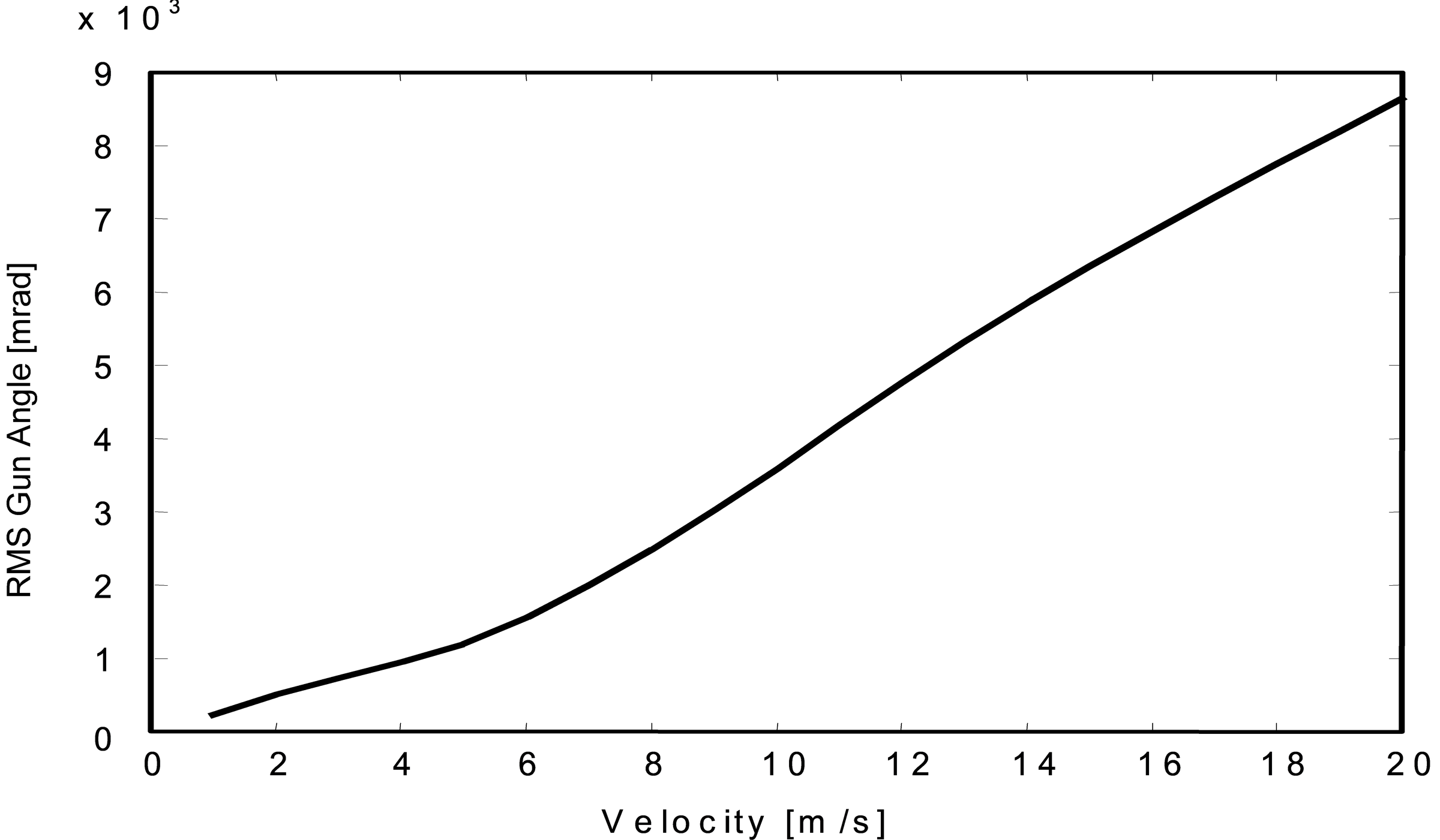
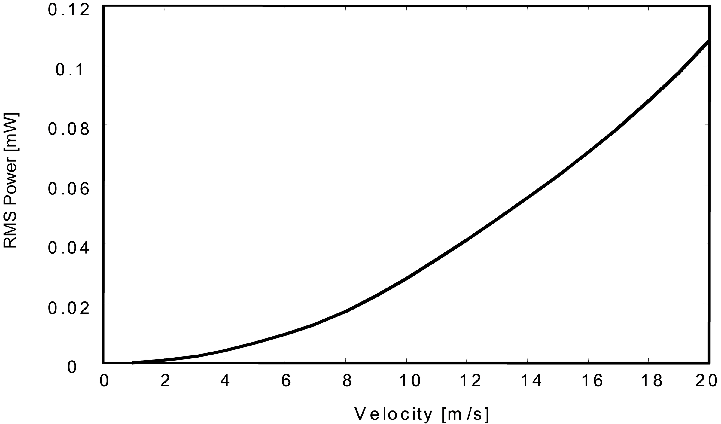
The plots for hull pitch rate feedforward for the rms gun motion and power are shown in Figures 8 and 9. These are very similar to those without the feedforward. In this situation, with no OOB, the datum case is obtained and at each vehicle speed the performance ratio of Equation (20) is zero. The results used for normalising the data are shown in Figures 10 and 11 and will be discussed here. It should be noted that because the model has no friction or non-linearities and treats the barrel and drive-line as rigid, these results show a very high performance, which is unrealistic. The plot of rms gun angle shows an increase with vehicle speed, which is to be expected because as the speed increases the disturbances impinging on the WCS are greater, Figures 14 and 15. A larger increase in the rms power with vehicle speed is seen in Figure 11.
Hull pitch rate and trunnion vertical acceleration feedforward
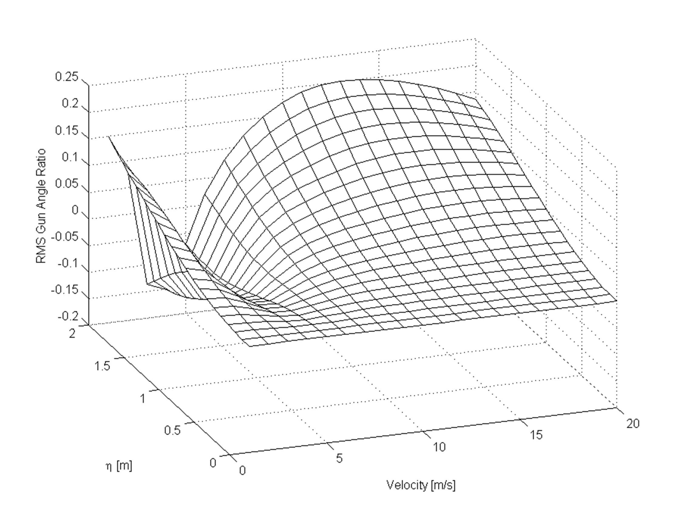
The most interesting case occurs when, in addition to the hull pitch rate feedforward, trunnion vertical acceleration is also included. The rms gun angle and power are shown in Figures 12 and 13. In Figure 12, for the rms gun angle, it is seen that the WCS is performing better than the control case at some vehicle speeds. This is especially so at 4 to 5m/s, where increasing the OOB has improved the performance. At 4m/s with the maximum OOB (η=2.0m) the WCS is performing 15% better. Under the worst conditions of maximum OOB and a vehicle speed of 13m/s the performance of the WCS is 20% worse. Thus, under all conditions considered, the WCS is within ±20% of the datum situation for gun motion. This variation is only slight and could be difficult to detect on a MBT WCS because of other effects, most notably friction. The performance of the WCS is made more interesting when the rms power is examined. This only shows a maximum increase of 70 times, which is one five-hundredth of the previous cases considered. From other studies, with more realistic models, this can be even less [4,6].
The reason for the improved performance with the trunnion vertical acceleration feedforward, is that the WCS is taking corrective action in anticipation of an error occurring; without feedforward, an error has to be present before any action is taken.
Vehicle model investigation
The above figures show that the best performance for the WCS occurs at a vehicle speed of between 4 and 5m/s. This improvement in performance is most likely due to the frequency content of the disturbance, which the WCS has to reject. Plots of the PSD for the hull pitch rate and trunnion vertical acceleration, from the MBT crossing random terrain, are shown in Figures 14 and 15. The plot for the trunnion vertical acceleration shows no easily discernible pattern, but the pitch rate has three distinct minima at 6, 13 and 19m/s. The first of these at 6m/s has the lowest value and is the most probable cause of the improved performance around 5m/s. There is no indication of the effect of the minima at 13m/s and 19m/s in any of the WCS results. These minima are caused by the wheel-base filtering of the vehicle.
Conclusion
A simple elevation model of a 120mm MBT main armament has been developed and used to investigate the effect of OOB on the performance of the WCS.
Without disturbance feedforward, or with only that from the hull pitch rate, it has been shown that the OOB has a significant effect on the angular motion of the gun and the power requirement. The angular motion of the gun has been shown to increase by almost 500 times and the power by just under 35000 times compared to the control case. When acceleration feedforward from the trunnions was introduced, these figures reduced to between -0.15 and 0.2, and 70 respectively.
Although the performance of the WCS with hull pitch rate and trunnion acceleration feedforward required more rms power than the OOB increase, its performance at rejecting hull motion, that is SR, improved.
The occurrence of a valley in the WCS characteristics at vehicle speeds of 4 to 5m/s is most probably caused by the wheel-base filtering of the vehicle.
It has been shown that the performance of the WCS deteriorates with increasing OOB, for an MBT that has an OOB main armament, as well as a mechanism for removing the static out-of-balance and no other form of augmentation. This is as predicted by the two quotations given in the introduction [1,2]. If feedforward from the vertical acceleration of the trunnions is incorporated into the WCS, its performance is significantly enhanced.
The results presented in this paper must be viewed with some caution because the model used was a significant simplification of the real situation, for more realistic models the reader is referred to [4,6].
References
[1] Rheinmetal, Handbook on Weaponry, second English edition, Rheinmetal GmbH, pp. 385-386, 1992.
[2] H.D. Warwick, “A Guide to the Design of Main Armament Gun Mountings for Armoured Fighting Vehicles (U)”, DERA Chobham Lane Chertsey UK, Report No. 82019, pp. 61-66.
[3] D.J. Purdy, “Modelling And Simulation Of A Weapon Control System For A Main Battle Tank”, Proceedings OfThe Eighth US Army Symposium On Gun Dynamics, 14-16 May 1996.
[4] D.J. Purdy, “Comparison of Balanced and Out Of Balance Main Battle Tank Armaments”, Proceedings OfThe Ninth US Army Symposium On Gun Dynamics, 17-19 Nov 1998.
[5] D.J. Purdy, “Main Battle Tank Stabilisation Ratio Enhancement Using Hull Rate Feedforward”, Journal of Battlefield Technology, Vol. 1, No. 2, 1998.
[6] D.J. Purdy, “An Investigation Into The Modelling And Control Of Flexible Bodies”, PhD. Thesis, Cranfield University (RMCS), England, 1994.
Appendix A
A further interesting result can be obtained by relating the acceleration at the trunnion to the pitch centre of the vehicle. Substituting Equation (9) into Equation (10), changes Equation (11) to:
(21)
Thus the effect of the disturbance Ωh(s) can be eliminated if:
(22)
This allows the OOB (η) to be selected to cancel out the disturbance caused by the hull pitching motion, assuming that the pitch centre of the vehicle is known and remains fixed and is given by:
(23)
The cancellation of the vehicle pitch motion due to the moment acting on the elevating mass caused by the drive, and is equal to that produced by the OOB for this motion. Under these conditions only a single feedforward sensor would be needed, such as an accelerometer at the pitch centre of the vehicle.