
Volume 2, Number 1, March 1999
A Trajectory Prediction for Segmented Projectiles Using CFD Code
Abstract
A new type of penetrator, the segmented projectile, has a great potential to be the future threat to modern armour. This paper describes the methodology currently chosen to allow for early design and study of the aerodynamic principles of the projectile system. In order to allow for fast turn around and flexibility in design and geometry, simplifying assumptions have been made in relation to otherwise very complex aerodynamics. The automatic trajectory prediction has been implemented into the computational fluid dynamics code and the resulting estimate of the mutual movement of segments is presented for a sample segmented projectile.
Introduction
An improvement in penetration efficiency is highly desirable to defeat current armour configurations. As a consequence, the increase in the penetration efficiency of projectiles continues to be the subject of intensive research. A good understanding of the hypervelocity impact process based on experimental studies was gained during the period 1959 to 1969, and was further complemented by the development of detailed numerical methods for solving impact problems [1].
Currently, high penetration of an armoured target is achieved by utilising hypervelocity long rod penetrators. Experimental data, presented by Hohler and Stilp [2], shows that penetration by a long rod penetrator increases proportionately to its impact velocity. However, at a certain velocity, the penetration tends to be limited by the classic jet penetration equation. In contrast, a new type of penetrator, the segmented rod projectile, appears to have greater potential for improved performance at velocities higher than 2000m/s. Studies to compare the performance of both types of penetrators revealed the superiority of segmented rod over long rod penetrators. Such studies [3,4] show that penetration efficiency, that is the depth of penetration divided by total length of penetrator (DOP/l),increases as the ratio of length to diameter, l/d, decreases. Further, physical experiments and simulation results [5,6] confirm that the efficiency of well-aligned segmented rod projectiles is greater than continuous rods. Moreover, Zukas [7] and Sorenson [8] conducted experimental and numerical investigations that demonstrated that the penetration performance of the segmented rod increases proportionately to the spacing between the segments.
While such gains in performance are impressive, there is real concern about the practicality of achieving the successful launch and flight of segmented rods for the following reasons:
- The design of the projectile needs to take into account space available in the barrel.
- The projectile must be in one piece while inside the barrel.
- The segments must be separated either immediately after launch or prior to impacting the target.
- The aerodynamics of air flow around the segments during separation and also in flight may generate undesirable effects on the stability, range and manoeuvrability of the projectile.
This paper describes current work aimed at designing of the segmented rod projectile system. The design process involved is, by its nature, multi-disciplinary. It consists of establishing the selection of alternative general design concepts, followed by evaluation of aerodynamics, trajectory prediction, calculation of penetration and finally, iterative modification of projectile design. Theoretical predictions are complemented by the manufacture of a prototype followed by firing experiments which would to some extent verify theoretical findings and confirm the correctness of the chosen design concept. At this early stage of design, only very basic theoretical capabilities have been established. Their application to a sample segmented projectile configuration is presented here.
Penetration
Penetration by conventional lower velocity long rods is influenced by both the penetrator and target material properties, and by strike velocity. Penetration by higher velocity segmented-rod projectiles occurs within the hydrodynamic regime and is achieved by a process of mutual erosion of projectile and target. During the penetration process, the shear stress generated in the target may be many orders of magnitude greater than the shear strength of the target. It has been shown [9] that the density and the length of the penetrator are of major importance in penetration, whilst the impact velocity is insignificant. An in-depth study of penetration of segmented projectiles has been conducted by one of the authors [10]. The results obtained by both experiments and numerical simulations are illustrated in Figure 1. They agreed with earlier findings, showing the improved penetration by the segmented rod projectiles, at high velocities.
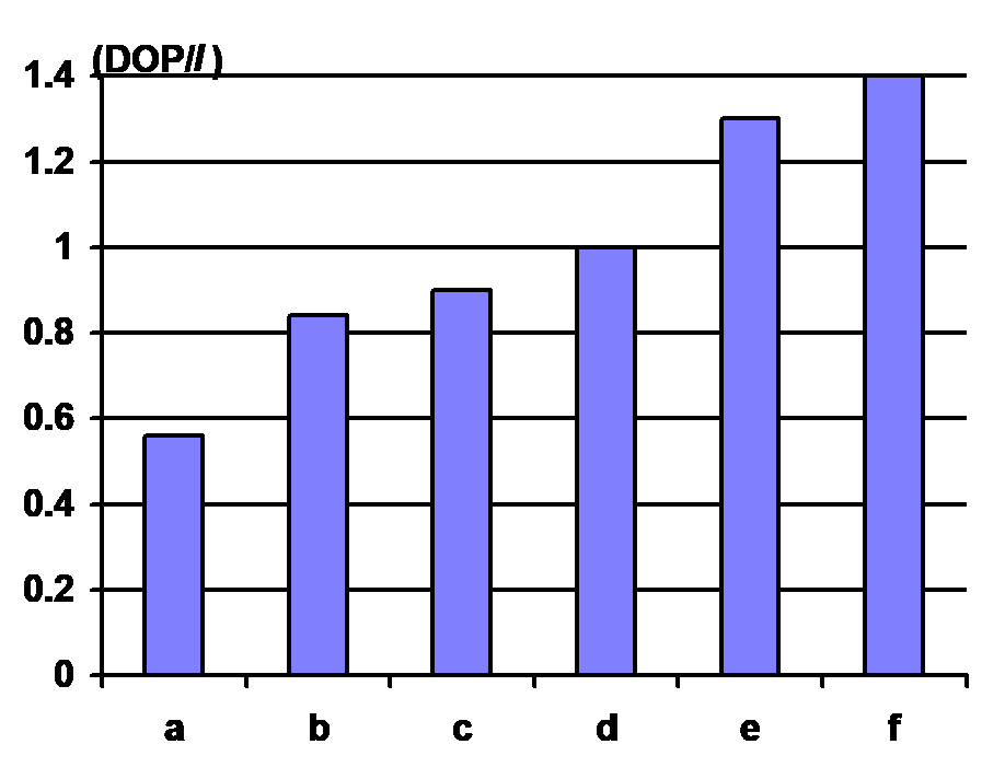
At hydrodynamic impact velocities, the interaction between projectile and target can be described by a simple fluid dynamic model. In this study the comparison of penetration performance between segmented rod and continuous rod projectiles has been investigated using the Autodyn Version 2.7. It was complemented by experimental firings. Simulation experiments with five segments projectile against a steel target with spacing distance to the diameter of the projectile, l/d=2.4 resulted in a penetration performance 30% better than continuous rods under the same conditions. The simulation results were confirmed by a series of firing experiments in similar conditions. Segmented rod projectiles, with spacing of l/d=2.25, at impact velocity of 1800m/s, achieved a penetration performance of 40% higher than a continuous rod of similar mass, diameter and velocity.
a - continuous rod at 1374m/s
b - continuous rod at 1690m/s
c - segmented rod spaced l/d=1 at 2000m/s
d - continuous rod at 1800m/s
e - segmented rod spaced l/d=1.5 at 1906m/s
f - segmented rod spaced l/d=2.25 at 1804m/s
Aerodynamics
The aerodynamics of segmented projectiles is complex even when the hypersonic effects of heat transfer and density are omitted. The physical processes in the launch and flight of segmented projectiles are not yet fully understood. The interference generated by one segment on the other can result in alteration of the projectile’s trajectory and may lead to a loss of accuracy at the target.
The complexity of the flow results from the segments being in relative motion, embedded in a non-uniform, viscous wake. Additionally, previous study [11] on the aerodynamics of segmented rod projectiles found that the flow field between segments is unsteady. The flow is characterised by the wave reflections between the rear of the leading segment and the front of the trailing segments. It is expected that proper modelling of the aerodynamics of segmented projectiles could be achieved using the solution of the fully time-dependent, three-dimensional Navier-Stokes equations with dynamic trajectory predictions for each component of the projectile. The trajectory prediction could be based on the integration of surface pressures on each of the components. The capabilities of such computation are currently being developed by the authors within the framework of 3D chimera grids. Such computations are very expensive. Therefore, for the purpose of this initial study, a very simple method was chosen in order to provide qualitative estimates. The choice was influenced by the need to ensure easy set-up for complex geometries and affordable computing times. This objective could only be achieved by making simplified assumptions relating to the physics of the flow.
The difference between three-dimensional and two-dimensional flows for projectiles is substantial. In order to provide an illustration, a simple comparison of the flow over a wedge and the flow over a cone is provided in Figure 2. The only obvious similarity is in the shocks generated at the nose. It can be seen that a two-dimensional supersonic flow is characterised by an attached, straight oblique shock wave from the nose and a uniform flow downstream of the shock with a stream line parallel to the wedge surface. A three-dimensional supersonic flow is also characterised by a shock wave, which emanates from the nose just as in the case of a two-dimensional flow.
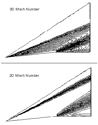
The flow over a three-dimensional body has an extra dimension in which to move, and hence it adjusts to the presence of the conical body in comparison to the two-dimensional body more easily. This results in a three-dimensional ‘relieving effect’, the consequence of which is that the shock waves are weaker, the surface pressure is lower and the streamlines above the body are curved rather than straight [12]. In comparison, a two-dimensional flow produces a stronger shock wave, higher surface pressure and straight streamlines above the surface. Therefore the two-dimensional calculation would tend to over-predict mutual displacements of segments, by comparison with the corresponding three-dimensional analysis. A caveat is that the two-dimensional calculation can be used with confidence to provide qualitative estimation of the stability of segmented projectile configurations in flight.
It is worth noting that another commonly used assumption that allows for fast 3D calculations is that of axisymmetric flow. However, this assumption would contradict the very nature of the problem under consideration and cannot be used here.
The two-dimensional Euler equations are solved by an in-house code. The equations for two-dimensional unsteady inviscid flow in the integral form which represents conservation of mass momentum and energy are:
where x and y are the Cartesian coordinates, and the integrals are taken over a control volume Ω, bounded by the curve δΩ. The conserved variable w and the Cartesian flux functions F and G are given by:
where ρ is the density, u, v are Cartesian velocity components, p is the pressure and h0 is the enthalpy. The time dependent flow equations are solved by a finite volume scheme based on the work of Jameson [13,14]. The spatial and temporal integrals are performed separately. Cell centre formulations have been developed in this code. The flux terms of flow equations are approximated by defining a residual Rj as the net flux at each point j.
The summation is carried out over the m edges that enclose the point j, with and consistent with an anticlockwise line integration. The fluxes for an edge are calculated by averaging the conserved variables at the two points that form that edge.
Given the solution and residuals for a point at time level n, the solution at the new time n+1 is obtained from a multi-stage Runga-Kutta scheme. For example, a three-stage scheme is:
where is the time step, which is taken as the minimum of the time step admitted by the Courant number for the cells surrounding a point. A is the corresponding area of the control volume.
To ensure stability, it is necessary to augment the governing flow equations with terms that represent artificial dissipitation. Two terms are introduced: a diffusive Laplacian smoothing to capture the shock waves, and ,a bi-harmonic diffusive smoothing acting as a low level background dissipation to reduce odd-even decoupling. A simple way to introduce these dissipation operators is to construct a Laplacian operator by taking the difference between the values at a given node and its nearest neighbours [15]. This is accomplished by looping over all edges in the mesh. Recycling the values for the Laplacian along edges, leads to a form for the bi-harmonic contribution. For node 0, we have:
where
with summations over n nodes, surrounding the point 0. ε and εare coefficients that incorporate pressure sensors. These two terms are then summed to produce the dissipative term. The characteristic analysis based on Rieman invariants is used to determine the values of the flow variables on the outer boundary of the grid.
The code was originally developed for transonic speed applications but in order to allow for the calculation of supersonic flows a special treatment in boundary conditions has had to be implemented. A different scheme is currently being implemented into 3D developments. This is better suited for hypersonic flow modelling.
The complexity of the geometry of mutually moving bodies has been resolved using triangular meshes. The mesh generation is based on the advancing front technique. The dynamic, moderate mesh movement during the time-dependent calculation utilises a spring analogy concept [16]. Namely, the mesh is interpreted as a spring network where each edge of each triangle represents a spring with stiffness inversely proportional to the length of that edge. The grid points along the outer boundary of the mesh are fixed and the instantaneous locations of the points on the surface of projectile’s segments are specified by the solution of trajectory equations. The positions of the interior nodes are found by solving the static equilibrium equations that result from a summation of forces at each node in both the x and y directions.
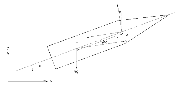
In predicting the trajectory of the segmented rod projectile, each segment is considered as a separate rigid body. From the diagram in Figure 3, the vertical and horizontal equation of motion can be described as follows.
Summation of forces in x direction:
Summation on forces in y direction:
Moments with respect to G:
with the following notation; mass (m) and gravitational acceleration (g) acting on the centre of gravity (G), lift (L) and drag (D) acting on the centre of pressure (P) and moment of inertia (I). Introducing:
and rewriting the equations of motion, a set of the first order differential equations is obtained:
The integration uses the three-stage Runge-Kutta scheme. In the calculations shown in this paper, the effects of gravity have been omitted. The effect of cross wind could not be implemented in a two-dimensional analysis. The code is run dynamically, that is the trajectory prediction is used to drive the mutual movement of segments and the alteration in the flow field angle of attack, followed by mesh movement procedures. The code can also be run in the quasi-steady state manner when the new position of components is determined at the end of the steady-state run and the user assumes the time interval. A new mesh needs to be generated for the next steady-state run using the altered geometry.
The code has been extensively validated for a range of steady-state cases. Unsteady flow, and moving mesh capabilities, have been validated for the NACA 0012 oscillating aerofoil.
Example of a segmented projectile design and numerical predictions.
In order to illustrate the potential of numerical modelling for moving segments, an example of a highly unstable segmented rod projectile was chosen and is shown in Figure 4. The distance between the centre of pressure and the centre of gravity of each segment is considerable.
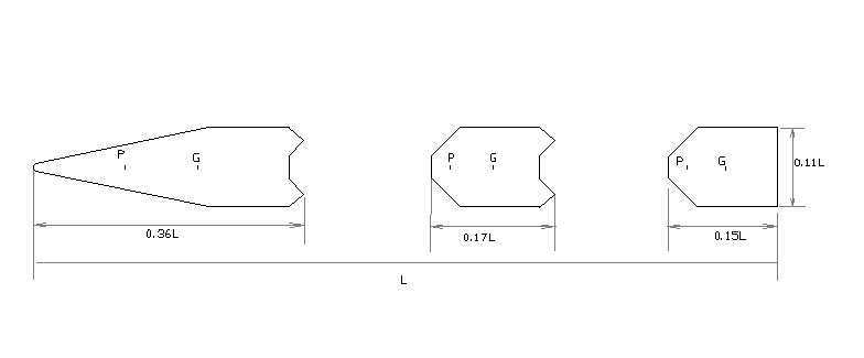
The front segment has a rounded nose to cater for the thermal effect at hypersonic velocity. The rear of each segment was designed with a gentle slope to minimise the effect of the expansion wave behind the segment. A frustum of a cone was designed at the rear of each segment to provide a suitable seat for the rear segment before separation as well as to push the centre of mass further forward.
The numerical results have been obtained for Mach4 flow at two initial angles of attack; 2° and 4°. In both cases, the unsteady calculations were started from initial conditions and carried out until the flow had been established. (A grid sensitivity study was performed for steady-state calculations). Then the iterative prediction of segment movement, change of computational mesh and the unsteady flow calculations were continued. The mesh movement capability allows only for moderate changes of segment position and the calculations were therefore stopped when the triangular cells became too distorted. If required, the calculation could continue. This would require the generation of a new mesh for the new configuration, interpolation of flow variables and a restart of the unsteady calculation. However, for the cases presented here, the loss of projectile’s stability would evidently occur well before such re-meshing is needed. The typical history of computational mesh changes is shown in Figure 5 for the initial and final segment configuration (obtained for Mach4, incidence α=2° flow).
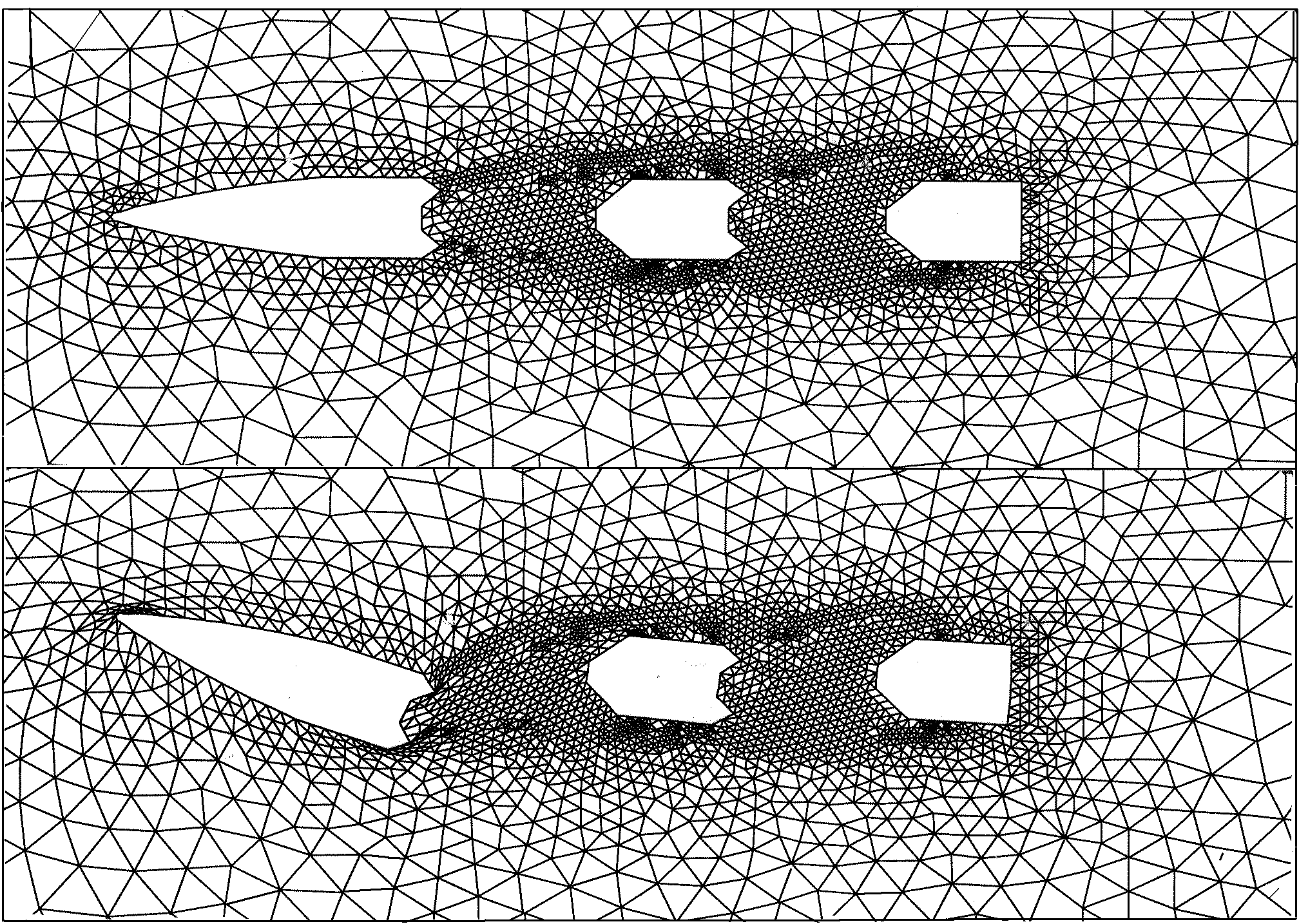
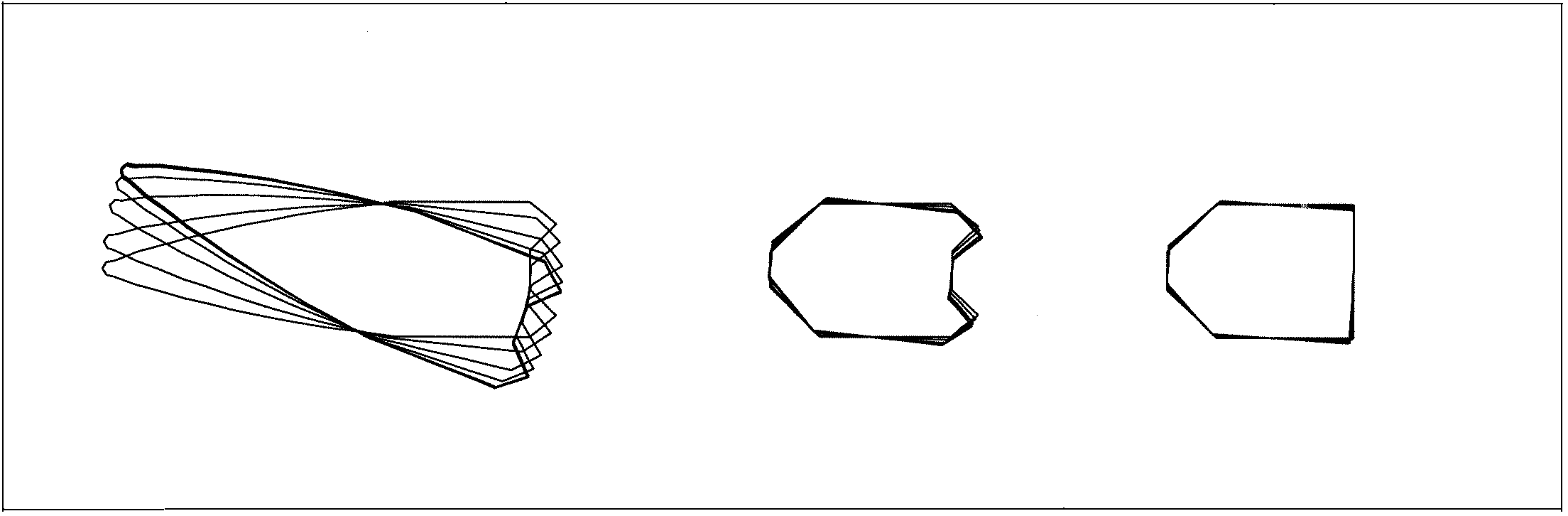
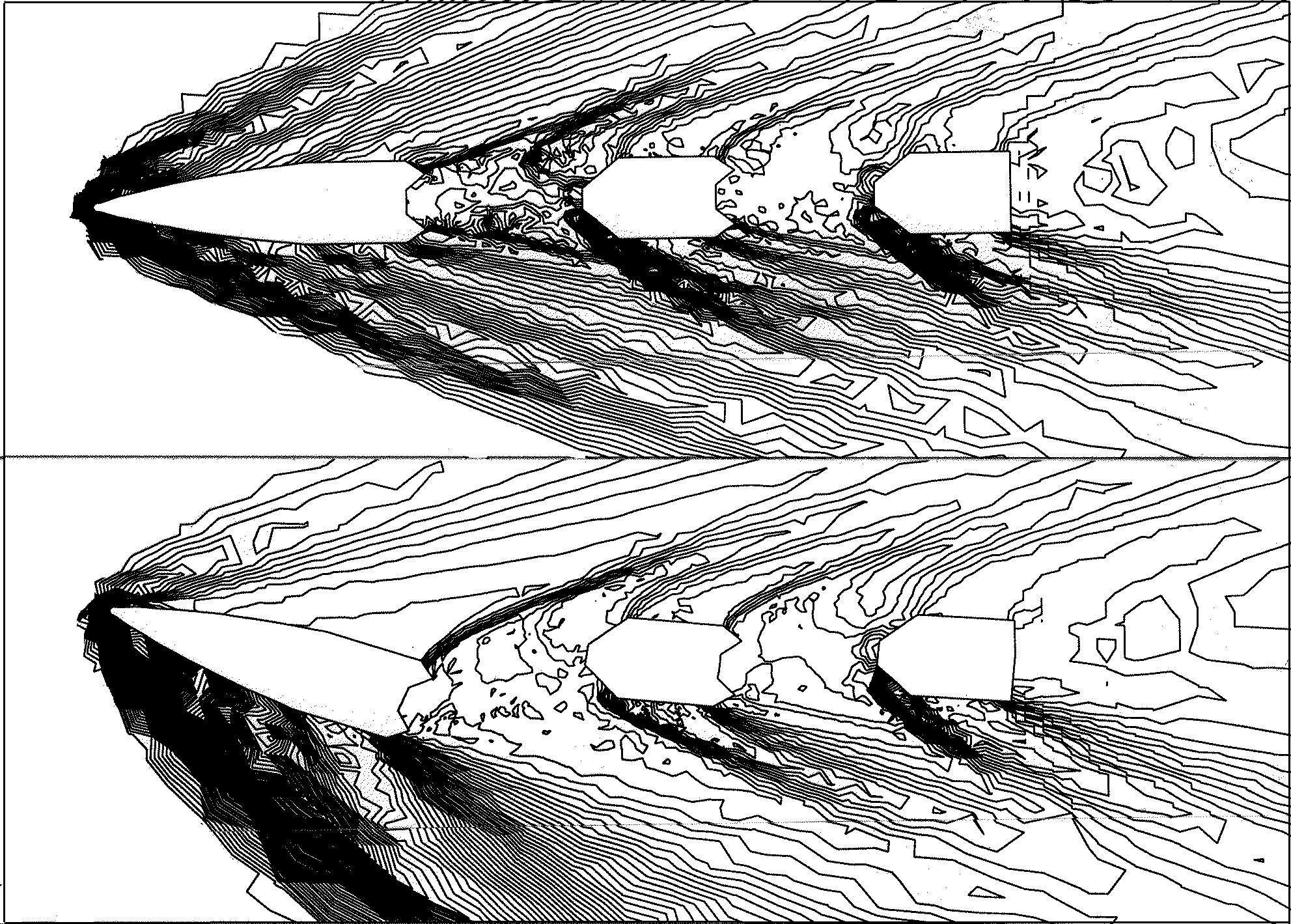
The final configuration corresponds to the time when the maximum acceptable stretching of the mesh was reached. The changes in terms of the segment’s position can be more clearly observed in Figure 6. The pressure contours corresponding to the established flow solution before movement of the segments are shown first in Figure 7 (top). The pressure contours for the final calculations are also shown in Figure 7 (bottom). These illustrations show dramatic change in flow characteristics.
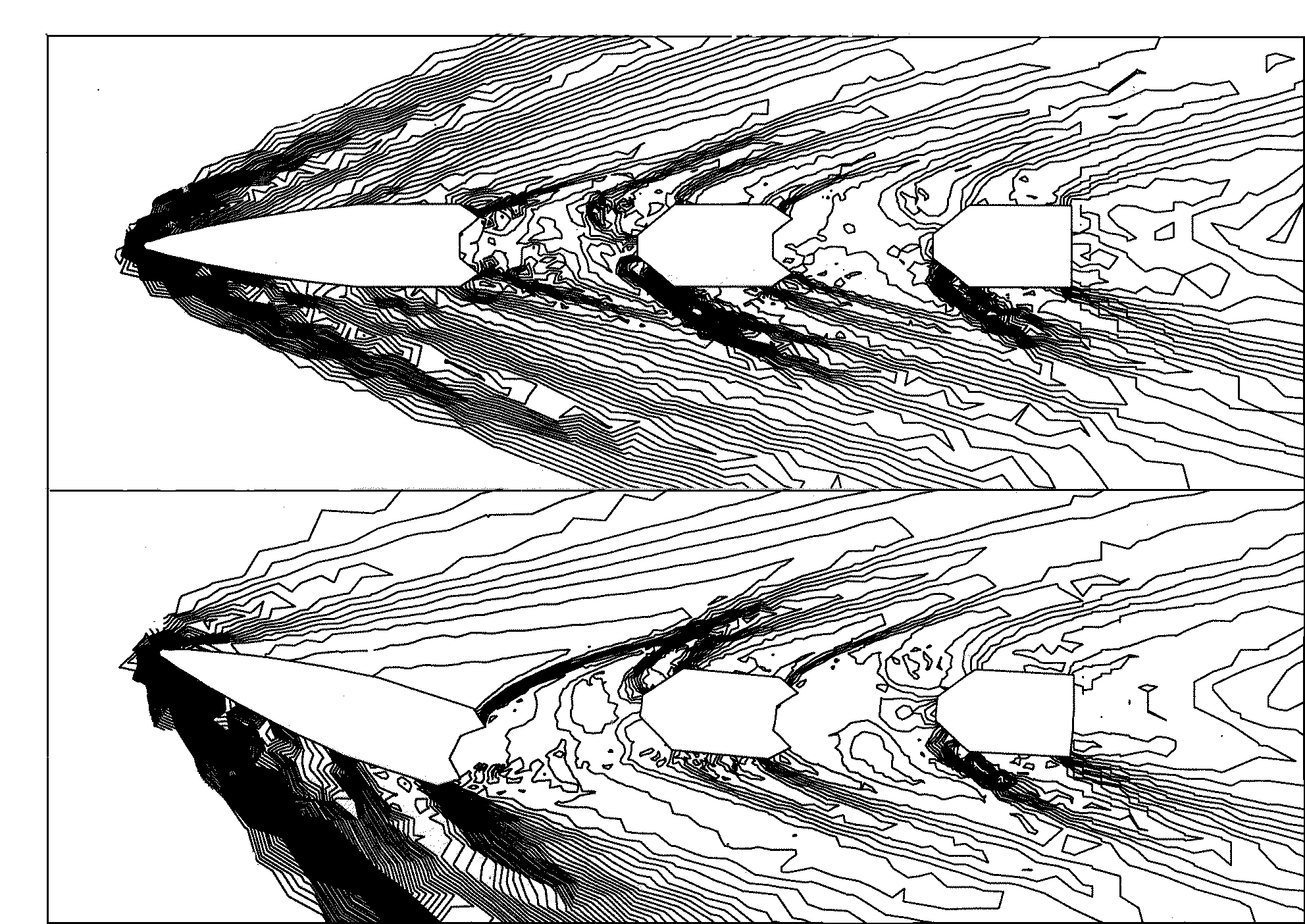
The position and strength of shocks has changed and for the final configuration the iteration of shocks generated by the first and second component can be observed. During the dynamic process of the segment’s motion the change in surface pressure distribution at the wind-side and lee-side of the projectile determines the direction of the segments’ movement.
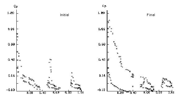
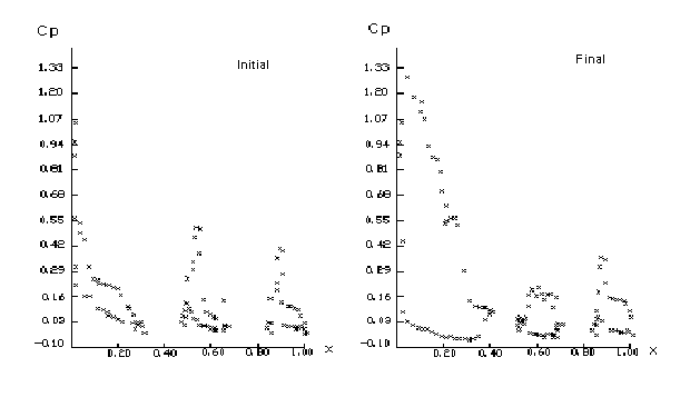
Detailed change in the pressure coefficient, Cp, as the function of the longitudinal position for the two configurations is shown in Figure 8. As expected, the increased angle of attack resulted in a substantial increase in lift for the first segment. The change in lift for the second and third segments was more moderate. A marked decrease in suction peaks for the two segments can also be observed. For the second test case for Mach4 flow at initial incidence of 4°, the loss of stability occurred much earlier, and the maximum stretch in the mesh was reached in a shorter time than in the first test case. This was to be expected since the initial lift for every component, which can be assessed from Figure 9, is higher than the corresponding lift in the first test case (Figure 8). For completeness, the pressure contours for the initial and final configurations are also shown in Figure 10. Although the character of the initial flow is similar in both cases, a very different flow pattern was obtained by comparison with the test case 1.
Conclusions
This paper presents a methodology used for initial investigation of the effect of supersonic flow on a segmented projectile trajectory. The method provides an easy to use and fast computational tool that allows for rapid engineering estimations. The ability of the method to predict loss of stability in the segmented rod projectile has been demonstrated. The work on further validation of the proposed approach is in progress. Verification of the theoretical prediction will be provided by the test firing of the chosen type of segmented projectile. Further study into the relevant flow physics will be carried out using a three-dimensional inviscid flow solver.
References
[1] C. Anderson and W. Johnson, ‘Overview of Hydrocode Development and Hypervelocity Impact’, Hypervelocity Impact Symposium, San Antonio, Oct 1986.
[2] V. Hohler and A. Stilp, ‘Penetration of Steel and High Density Rods in Semi-Infinite Steel Targets’, Proceedings of the 3rd International Symposium on Ballistics, 1977.
[3] D. Orphal and R. Franzen, ‘Penetration Mechanics and Performance of Segmented Rods Against Metal Target’, International Journal of Impact Engineering, Vol. 10, pp. 427-438, 1990.
[4] D. Scheffler and J. Zukas, ‘Numerical Simulation of Segmented Penetrator Impact’, International Journal of Impact Engineering, Vol. 10, pp. 487-497, 1990.
[5] A. Charters, The Penetration of Rolled Homogeneous Armour By Continuous and Segmented Rod at High Velocity: Theory and Experiments, (AD-B113 189), General Research Corporation, Santa Barbara, Dec 1986.
[6] J. Cuadros, ‘Monolithic and Segmented Projectile Penetration Experiments in the 2 to 4 km/secs Impact Velocity Regime’, International Journal of Impact Engineering, Vol. 10, pp. 147-157, 1990.
[7] J. Zukas, Numerical Simulation of Semi-Infinite Target Penetration By Continuous and Segmented Rods, Technical Report BRL-TR-3081, Ballistic Research Laboratory, Aberdeen Proving Ground, Maryland, Feb 1990.
[8] B. Sorenson, K. Kimsey, G. Silsby, D. Scheffler, T. Sherrick and W. De Rosset, ‘High Velocity Penetration of Steel Target’, International Journal of Impact Engineering, Vol. 11, pp. 107-119, 1991.
[9] P. Smith and J. Hetherington, Blast and Ballistic Loading of Structures, Butterworth and Heinemann Ltd., pp. 234-235, 1994.
[10] A. Shohaimi, J. Hetherington and D. Leeming, ‘Penetration Performance of Segmented Rods - Comparison with Continuous Rods at High Velocity’, Journal of Battlefield Technology, Vol. 1, No. 1, Mar 1998.
[11] D. Young, ‘A Study of Segmented Projectile Aerodynamics’, Proceeding of 48thAeroballistic Range Association Meeting, Austin, Texas, 5-9 Nov 1997.
[12] J. Anderson Jr., Fundamentals of Aerodynamics, 2nd edn McGraw Hill Inc., pp. 474-477, 1991.
[13] A. Jameson, W. Schmidt and E. Turkel, ‘Numerical Solution of the Euler Equations by Finite Volume Methods Using Runge-Kutta Timestepping Schemes’, AIAA Paper No. 81-1259, 1981.
[14] A. Jameson, J. Baker and N. Weatherill, ‘Calculation of Transonic Flow Over a Complete Aircraft’, AIAA Paper No. 86-0103, 1986.
[15] A. Evans, M. Marchant, J.Szmelter and N. Weatherill, ‘Adaptivity for Compressible Flow Computations Using Point Embedding on 2-D Structured Multiblock Meshes’, International Journal of Numerical Methods Engineering, Vol. 32, pp. 896-919, 1991.
[16] John T. Batina, ‘Unsteady Euler Algorithm with Unstructured Dynamic Mesh for Complex-Aircraft Aerodynamic Analysis’, AIAA Paper No. 89-1189, Apr 1989.