
Volume 2, Number 1, March 1999
Ceramic Armour
Abstract
This paper reviews the failure mechanisms that occur when a projectile penetrates a ceramic armour. The advantages and disadvantages of using a ceramic-based system are presented and the application of the different ceramics available is discussed.
Introduction
It has long been accepted that ceramic materials can play an important part in ballistic protection. Their high hardness and low density make them ideal candidates for armour systems. In fact, it has been known since 1918 that a thin, hard enamel facing on a metal significantly enhances its ballistic resistance [1]. However, this work was never exploited until 1962 when R.L. Cook of the Goodyear Aerospace Corporation developed the first hard-faced composite armour [2]. Since then, extensive research has been carried out to examine the optimal properties, construction and uses of ceramic armour technology.
The first real use of ceramic armour technology was in US helicopters in the 1960’s. Low level sorties in the jungle of Vietnam had made the helicopter and crew vulnerable to small arms fire. Hence, in 1965 the first [3] ceramic-based aircrew protection vest went into production. In 1966, the first monolithic boron-carbide vest was issued along with other improvements to the protection of the crew using parasitic airframe-mounted armour panels. In 1967, the integrally armoured helicopter seat was developed and by placing the ceramic tiles closer to the crew the area and weight of armour required for crew protection was minimised.
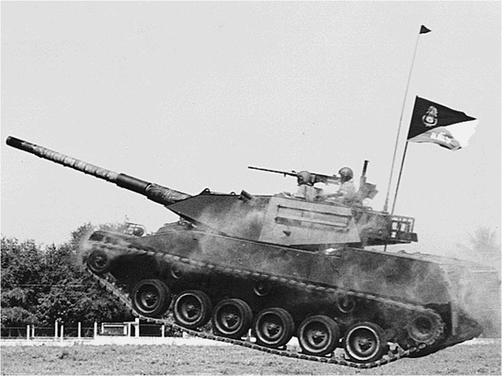
Ceramics have since been used in many civil and military applications where protection is required. Their high compressive strength and low density have led to the replacement of some relatively heavier types of armour. They have also provided opportunity to provide protection where metals had previously failed. These have included protective vests for the police force, parasitic armour for helicopters, transport aircraft, trucks [4], troop carriers, light tanks (Figure 1), hovercrafts and main battle tanks (MBTs).
Mechanisms of ceramic armour failure
Although there was early interest in the use of ceramic materials as armours, the exact mechanisms of failure remained a mystery. Wilkins and his colleagues [5,6,7] provided the first notable analysis on ballistic failure processes in ceramic faced armours. Wilkins recognised that in order to optimise a two-component ceramic armour system it is necessary to understand the interactions between target and projectile. Using high-speed photography, flash x-ray and numerical models he was able to evaluate the ballistic failure processes. In the first 9µs of penetration it was postulated [8] for small calibre ammunition:
- The projectile tip is destroyed.
- A fracture conoid initiates at the interface between the projectile and the target. The cones that are formed spread the load of the projectile onto a relatively wide area enabling the energy of the impact to be dissipated by the plastic deformation of a ductile backing material.
- The backing plate yields at the ceramic interface.
- The tension that results in the ceramic as it follows the motion of the backup plate initiates an axial crack. This failure mechanism has since been argued as being a result of the impedance mismatch in the two-composite structure (for example, see [9]).
For larger threats such as Armour Piercing Discarding Sabot (APDS) rounds, thicker sections of ceramic and backing material are required. The failure patterns that occur when a rod penetrates a ceramic target are shown in a recent numerical simulation (Figure 2) using the hydrocode AUTODYN-2D [10]. Moreover, Shockey et al [11] performed experimental long rod penetration studies into thick blocks of confined ceramic in an attempt to discover the properties governing penetration resistance. They postulated that:
![The result of a computer simulation of a rod penetrating a ceramic target (after [10]) - the light areas indicate the presence of failure.](/journals/journal-of-battlefield-technology/volume-02/issue-01/assets/2-1-1-hazell/figures/figure02.png)
- Tensile fracture occurs soon after impact close to the rod periphery. The stress fields are initially elastic and the largest tensile stresses are in the radial direction. Therefore, the cracks that form, (normal to the direction of the maximum principal stress) are ring cracks concentric about the impact site.
- These cracks initially grow to approximately 1mm below the surface. However, upon continued loading a few ring cracks grow, following the paths normal to the direction of the principal tensile stress. Thus several large Hertzian cone cracks extend throughout the block, assuming trajectories 25-75º from the initial normal-to-the-surface direction (see Figure 2).
- As the rod continues to advance, the compressive strength is exceeded in material directly below the penetrator. Microcracking occurs in a shallow zone near the penetrator tip, and the stress field changes in character. The principal tensile stresses are now in the circumferential direction that invoke six to twelve large radial cracks propagating outward from the impact centre like spokes from a hub.
- A fourth type of crack finally develops beneath the impact surface and runs parallel to it - probably during unloading. These intersect cone and radial cracks to produce fragmentation and form the residual crater.
Further insight into the exact failure mechanisms can be taken from a comparative study between the fractography of the ceramic rubble caused by ballistic impact and that of quasi-static experiments. These studies indicate both compression and tension loading play a role in ballistic failure [12]. However, because of their brittle nature, ceramics require only a small amount of the projectile’s impact energy to cause fracture [13]. Of more significance, is the impact energy that is converted into kinetic energy for ejected fragments [14]. Woodward et al [15] analysed the degree of fragmentation in ceramic material that resulted from ballistic impact by tungsten alloy projectiles. Using a wide range of targets of varying toughness, they found that there was a correlation between the increased degree of fragmentation and reduced ceramic toughness. Moreover, introducing front confinement resulted in greater overall fragmentation due to the formation of a higher intensity relief wave.
Although macro-crack propagation is the predominant failure mode of dynamically loaded ceramic, it is not the only failure mechanism that occurs during penetration. Comminution of the ceramic (that is, the reduction of intact ceramic to small fragments) just below the penetrator (Figure 3) is also important, especially when the velocity of impact increases. The importance of this zone was first realised by the late John Mescall [16] and has since been named after him by some authors [17]. At high pressures, the small unevenly shaped particles can lead to erosion of the projectile and resistance to penetration.
![Damage caused by a projectile penetrating ceramic (after [24]).](/journals/journal-of-battlefield-technology/volume-02/issue-01/assets/2-1-1-hazell/figures/figure03.png)
Evidence for ceramic comminution during projectile penetration has been provided by James [18]. Using thin lead fiducial markers sandwiched between ceramic targets, he was able to x-ray the extrusion of the marker into the comminuted zone ahead of the penetrator. Measurements were taken of the extent of the forward disruption of the comminuted zone for both alumina and silicon carbide ahead of the penetrator tip. In both cases, for a projectile impact at 1800ms-1, the zone extended approximately 13.5mm.
The formation of the comminuted zone has been described as being caused by the compressive strength of the material being exceeded (that is, crushing) [20]. However, further comminution can accumulate ahead of the penetrator by the arrival of a tensile failure wave from the lateral surfaces of the target (if the target is thick enough). This has been demonstrated by the work of Vlasov et al [21] who showed that the penetration velocity, measured at the projectile – target interface, was affected by the target lateral dimensions. The time of ‘resistance to penetration’ was shortened by reducing the lateral dimensions indicating that greater fragmentation had occurred ahead of the penetrator. Vlasov et al postulated that this was either a result of the lateral free surface reflection of the expanding stress waves intersecting at the centre of the target or because of crack nucleation and propagation from the periphery. In either case, for large calibre threats this study indicates that an increase in the lateral dimensions of the ceramic tile leads to an increased resistance to penetration.
The performance of ceramic armour
Perhaps one of the most difficult items to value is human life. Yet, it is quite clear that policy decisions are made which determine an acceptable cost of armour protection. The valuation of life differs from country to country and may well depend on the rank of the individual within the vehicle (that is, the value of life is dependent on the persons contribution to the welfare of others [22]). Another factor, which is considered when a vehicle is armoured, is its perceived value. This may not necessarily be in terms of the cost of developing and manufacturing the vehicle but may take into account the vehicle’s strategic importance on the battlefield. Careful consideration is given to the level of protection provided by the armour for each application. However, where budgetary constraints are in place, it is wise to evaluate the optimum cost to provide an acceptable level of protection. Evaluating the cost per unit performance of the armour can help this decision.
To evaluate the cost per unit performance of different ceramic materials a performance measure is required that takes into account the protective capability of the armour and its weight (or density). Various methods have been suggested to measure the performance of a ceramic. However, the most commonly used is the differential tile efficiency, Δec. The reason for its popularity is that it has been shown to be unaffected by test conditions and is therefore more readily comparable with different researchers.
Initially, firings are conducted into a homogenous semi-infinite target (steel). The penetration depth into the steel is measured and compared to penetration depths that are achieved when a ceramic of a fixed thickness is adhered onto a similar semi-infinite target. A cover plate can be added to evaluate the effect of confinement.
The differential tile efficiency is defined as:
(1)
where P∞ is the depth of penetration into an infinite target (steel), Tcp is the thickness of a cover plate, Tc is the thickness of the ceramic tile, ρst and ρc is the density of the steel and ceramic respectively and Pst denotes the depth of penetration into the steel substrate (behind the ceramic tile).
The measurement of performance (that is, the protective capability based on weight) was taken from the open literature. The relative costs for each ceramic are given below in Table 1 [23].
It should be noted that comparisons like this are not absolute, as the actual price will depend on the method of production, quantity ordered and the suppliers pricing policy.
Franzen et al [24] presented calculated differential efficiency factors for three types of ceramic: boron carbide (B4C), aluminum nitride (AlN) and silicon carbide (SiC). In each case, the differential efficiency factor was calculated from reverse ballistic tests, for the velocity range 1.5–4kms-1. Comparing this, to the data of Wilkins et al (see [25]) for a 99.5% alumina (AlsO3) we are able to plot the performance against the relative cost of these four ceramics (Figure 4). The figure illustrates why alumina is still the most readily used material for protecting vehicles. Increasing the cost of the ceramic five-fold only results in an increased performance of 25%.
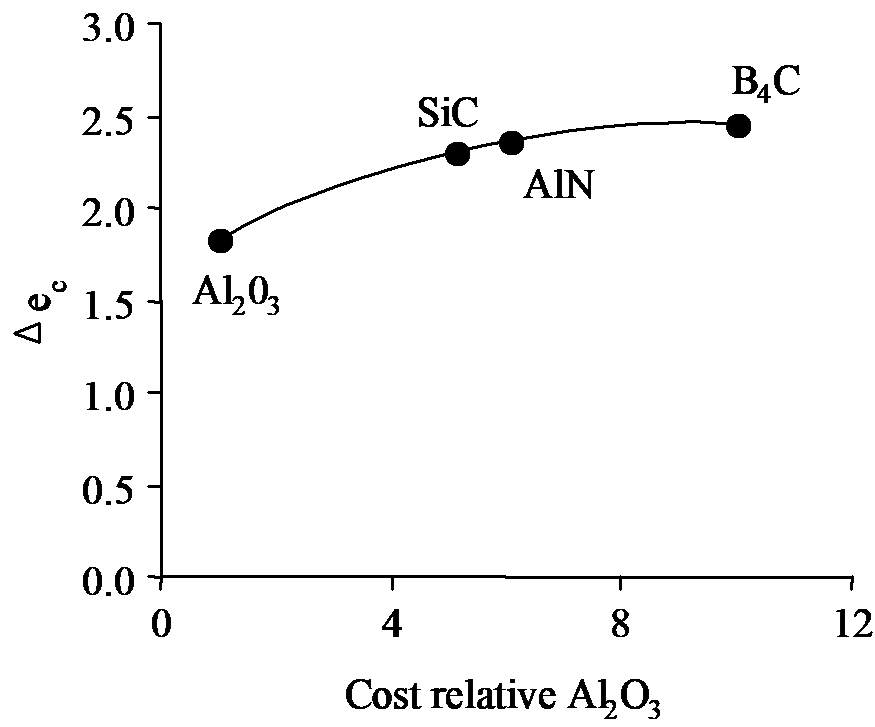
However, the armour designer may consider that a reasonable cost increase depending on the perceived value of the vehicle. For a helicopter, which has a high unit cost and for which it is necessary to maintain a low weight, the armour designer might do well to consider a ceramic such as silicon carbide or boron carbide. Conversely, for a MBT, where the addition of one to two tonnes of armour would have little or no effect on the vehicle’s functionality, it would be appropriate to use a cheaper material.
For lower energy threats alumina is still the most commonly used ceramic. Figure 5 shows a comparison between a number of different armour types and the weight that is required (per unit area) to defeat a 7.62mm NATO AP round. To reduce the weight of the armour by half requires a cost increase of approximately 2.5 times. Reducing the weight further (that is, by using ceramics and hi-tech materials that are more expensive), increases the cost substantially with very little added benefit.
![Performance vs Cost relationship for armours to defeat 7.62mm NATO AP ammunition. Cost relative to armour steel (B555) (after [23]).](/journals/journal-of-battlefield-technology/volume-02/issue-01/assets/2-1-1-hazell/figures/figure05.png)
Although ceramic armours are parasitic in nature in that they are unable to sustain tensile loads, the application of ceramic armour to vehicles can lead to reductions in the overall vehicle weight. Reducing the weight of the vehicle armour may lead to savings elsewhere. The added cost of the protection may well prove to be worthwhile if it means that the engine, transmission, driveline and suspension system do not require upgrading.
Moreover, if ceramics provide weight savings to an armoured fighting vehicle (AFV) in comparison to other more conventional methods of protection, opportunities become available whereby vehicles are easier to transport by air. Table 2 shows the airlift capability of two carriers that are expected to be in service with NATO forces for the next decade [26]. The infantry fighting vehicles (IFV) currently in service (the US Bradley and the British Warrior) weigh around 23 tonnes (the new Multi-Role-Armoured-Vehicle (MRAV) is expected to weigh 30 tonnes). Therefore, there is little scope for increasing the level of protection on these vehicles if they are to be transported by air.
This weight saving advantage may also be enhanced by the use of ceramic appliqué armour packs in the design of AFVs. Appliqué packs of armour can be transported separately from the vehicle and attached at the destination therefore maintaining logistic flexibility. In addition, the MBT such as the British Challenger II, which weighs sixty-three tonnes, is limited by mobility in urban areas due to bridges unable to withstand the load. Or, as was found in the Falklands conflict, vehicles with large ground pressures are unable to traverse boggy fields. A reduction in the overall weight of this kind of vehicle will improve its flexibility in battle. The overall effect on the military resources results in a more mobile, easily transportable and flexible fighting force.
The future
Ceramic appliqué armour systems of various constructions have been proven to provide protection against small arms, heavy machine gun and to a certain extent cannon fire. For instance, ceramic-appliqué has been recently fitted to the Swiss-designed Piranha wheeled armoured vehicle. It is reported to provide all round immunity from 14.5mm BS 41 armour-piercing bullets and protection over the frontal arc of ±30° against APDS projectiles of 30mm calibre [27]. However, complete protection from higher calibre ammunition is still not possible without resorting to large volumes of material.
In the future, penetrators will get longer and faster. Delivery systems will be developed that launch projectiles to higher velocities, they will reduce in size and become more widespread. The nature of the projectile will change from that of a single, homogeneous penetrator to a segmented or telescopic design. Therefore, to keep abreast of these developments in penetrator technology, the armour designer needs to continually enhance existing armour and develop new methods of protection.
Alumina is still the most cost-effective ceramic for providing reasonable protection. The use of higher performing ceramics such as silicon carbide and boron carbide is relatively costly for large volume applications due to processing difficulties. As ceramic processing routes improve, so will ceramic armour. Furthermore, as we understand more about the exact failure mechanisms that occur during projectile penetration, better ways of constructing ceramic-based armour systems will be found.
References
[1] R. Rolsten, E. Bodine and J. Dunleavy, “Breakthrough in Armour”, Space and Aeronautics, Vol. 50,No. 1, pp. 55-63, 1968.
[2] G. Savage, “Ceramic Armour”, Journal of the Institute of Metals, Vol. 6. No. 8, pp. 487-492, 1990.
[3] R. Bart and J. Lindberg, “Ceramic Bodyguards”, Advanced Materials & Processes Inc. Metal Progress, Vol. 9, pp. 69-72, 1987.
[4] R. Ogorkiewicz, “Armoring Vehicles for Peacekeeping”, International Defense Review, Vol. 27, No. 2, pp. 33, 1994.
[5] M. Wilkins, C. Honodel and D. Swale, An Approach to the Study of Light Armor, Lawrence Radiation Laboratory, Livermore, UCRL-50284, June 1967.
[6] M. Wilkins, C. Cline and C. Honodel, Fourth Progress Report of Light Armor Program, Lawrence Radiation Laboratory, Livermore, UCRL-50694, 1970.
[7] M. Wilkins, R. Landingham and C. Honodel, Fifth Progress Report of Light Armor Program, Lawrence Radiation Laboratory, Livermore, UCRL-50980, January 1971.
[8] C. Cline and M. Wilkins, “The Importance of Material Properties in Ceramic Armor”, Proceedings of the Ceramic Armor Technology Symposium (USA), pp. 13-18, January 1969.
[9] M. Stephenson, A Study of the Ballistic Performance of Lightweight Armours against Small Arms Ammunition, PhD Thesis, City University, London, 1991.
[10] P. Hazell, The Failure of Ceramic Armour Subjected to High Velocity Impact, EngD Thesis, Cranfield University, October 1998.
[11] D. Shockey, et al, “Failure Phenomenology of Confined Ceramic Targets and Impacting Rods”, International Journal of Impact Engineering, Vol. 9, No. 3 pp. 263-275, 1990.
[12] C. Tracy, M. Slavin and D. Viechnicki, “Ceramic Failure During Ballistic Impact”, Advances in Ceramic: Fractography of Glasses and Ceramics, Vol. 22, pp. 295-306, 1988.
[13] M. Mayseless, et al, “Impact on Ceramic Targets”, Journal of Applied Mechanics, Vol. 54, pp. 373-378, 1987.
[14] R. O’Donnell, et al, “Fragmentation of Alumina in Ballistic Impact as a Function of Grade and Confinement”, Proceedings of the 12th International Symposium on Ballistics, San Antonio, Texas, USA, November 1990.
[15] R. Woodward, et al, “A Study of Fragmentation in the Ballistic Impact of Ceramics”, International Journal of Impact Engineering, Vol. 15, No.5, pp. 605-618, 1994.
[16] J. Mescall and C. Tracy, “Improved Modeling of Fracture in Ceramic Armor” Army Science Conference, U.S. Military Academy, West Point, New York, pp. 41-53 1986.
[17] D. Curran, et al, “Micromechanical Model for Comminution and Granular Flow of Brittle Material Under High Strain Rate Application to Penetration of Ceramic Targets”. International Journal of Impact Engineering, Vol. 13, No. 1, pp. 53-83, 1993.
[18] B. James, “Direct Evidence for Ceramic Comminution Ahead of Penetrator”, Proceedings of the 17th International Symposium on Ballistics, Midrand, South Africa, March 1998.
[19] R. Klopp, and D. Shockey, Tests for Determining Failure Criteria of Ceramics under Ballistic Impact, US Army Research Office, AD-A256 652, 1992.
[20] J. Sternberg, “Material Properties Determining the Resistance of Ceramics to High Velocity Penetration”, Journal of Applied Physics, Vol. 65, No. 9, pp. 3417-3424, 1989.
[21] A. Vlasov, et al, “Kinetics of the High Velocity Penetration for Brittle Materials”, Proceedings of the 17th International Symposium on Ballistics, Midrand, South Africa, March 1998.
[22] M. Jones-Lee, “Safety and the Saving of Life: The Economics of Safety and Physical Risk”, Cost-Benefit Analysis, 2nd Edition, R. Layhard and S. Glaister (editors), Cambridge University Press, 1994.
[23] C. Roberson, “Ceramic Materials and their Use in Lightweight Armour Systems, Lightweight Armour Systems Symposium, Royal Military College of Science, UK, 28-30 June 1995.
[24] R. Franzen, D. Orphal and C. Anderson Jr, “The Influence of Experimental Design on the Depth-of-Penetration (DOP) Test Results and Derived Ballistic Efficiencies”, International Journal Impact Engineering, Vol. 19, No. 8, pp. 727-737, 1997.
[25] C. Anderson Jr. and S. Royal-Timmons, “Ballistic Performance of Confined 99.5%-AL2O3 Ceramic Tiles”, International Journal of Impact Engineering, Vol. 19, No. 8 pp. 703-713, 1997.
[26] Jane’s All the World’s Aircraft 1996-97, P Jackson (editor), Jane’s Information Group Ltd, 1996.
[27] R. Ogorkiewicz, “Lightweight Armoured Systems, an Overview” Lightweight Armour Systems Symposium, Royal Military College of Science, Shrivenham, 12-14 November 1997.