
Volume 1, Number 3, November 1998
A Review of Transmission Systems for Tracked Military Vehicles
Abstract
The transmissions and drivelines for many wheeled and, especially, tracked military vehicles have diverged considerably from those of their civilian counterparts over the last 40 years. The high performance, good cross-country mobility and ‘drivability’ demanded by military users have lead to complex, sophisticated and specialised transmissions, which are usually produced in small numbers and often owe little to commercial practice. Economic constraints on defence procurement and recent developments in the commercial sector have narrowed the technology gap but, as yet, resulted in little collaboration between the two fields. This paper reviews the development of transmissions for tracked military vehicles and examines the potential for greater cross-fertilisation and collaborative development. It is considered that, especially for lighter vehicles such as armoured personnel carriers, it would be technically feasible and economically beneficial to synthesise military transmissions largely from commercial hardware.
Introduction
Military vehicles include a wide range of types, from motorcycles to main battle tanks. Many have equivalents on the civilian market; sometimes the military vehicle is sourced directly from it. Other classes of vehicle may be developed from civilian designs or indeed, like Supercat for example, provide a civilian opportunity from a military requirement. Modern tanks, which are fast tracklayers, stem from a common heritage of slow tracklayers, which included early tanks and tractors.
Military vehicles, with the exception of staff-cars and some load carriers, require much better off-road mobility than most other vehicles. Tracked vehicles, by their very nature, have good traction, low ground pressure and hence good cross-country mobility. However, they are difficult to steer; most tracklayers are steered by allowing or imposing a difference in speed on the two tracks. This is called skid steering, and requires a complex transmission system to provide the finesse of control needed for fast tracklayers.
Early military vehicle transmissions drew heavily on technology and hardware from the commercial sector. However, as military demands have become more varied and taxing, there has been a trend, particularly since the 1939-45 war, towards ‘military specials’ – sometimes almost regardless of cost. For the future, it is likely that the escalating cost of small volume production will necessitate a return to greater interdependence between commercial and military technology and, consequently some compromise of performance.
Evolution of tracked vehicle transmissions
There are four major methods of steering tracked vehicles: auxiliary steering wheels, track setting, vehicle articulation and skid steer. Though examples of all are to be found, only skid steer has achieved general widespread application and is singular in offering the facility to achieve pivot turns. Skid steer is achieved by allowing or forcing the right and left-hand tracks to move at disparate speeds, thereby inducing the vehicle to slew. It is relevant to examine the development of skid steer systems briefly in order to arrive at modern requirements for such systems and propose ways of realising them. Skid steer can also be used for wheeled vehicles; some are in current service, for example the GIAT AMX10.
Early systems
The earliest skid-steered tanks used separate engines and transmissions for each track; an engine man and a gearman being required for each side of the vehicle to control their respective systems. Mobility therefore required a crew of five, including the driver, who shouted orders to the others as best he could. This cumbersome approach was quickly supplanted by single engines and by transmission systems of much less mechanical (and human) complexity.
Clutch-brake steer
In this system, (Figure 1) the engine, through a change speed gearbox, drives a transverse cross-shaft, via which the right and left hand sprockets are driven through suitable final drive gearboxes. Each side of the cross-shaft carries a clutch and, outboard of it, a brake.
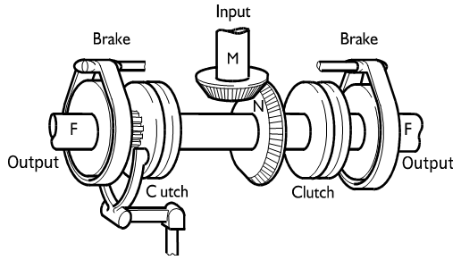
To steer, the driver first disengages the clutch on the appropriate side, thereby interrupting the drive to that track and inducing a free turn. The vehicle's response depends on the going: on soft, heavy terrain or an up-grade, the undriven inside track will rapidly slow, stop, or in extremis, start to rotate backwards. On a hard, level road the inside track will slow to give a turn radius in the order of 50-100m for a vehicle of typical aspect ratio. Under such conditions, the undriven track may be slowed further, to achieve a tighter turn, by applying the brake outboard of its (now open) clutch.
Ifthe brake is applied hard enough to stop the inside track completely, a locked turn will result, with the vehicle pivoting about the inboard track. By feathering the brake to produce a controlled amount of slip, the driver can (notionally) achieve any turn radius between the 'free' and 'locked' turn conditions. In practice, this is difficult with this force controlled method of turning because, once yaw of the vehicle is induced, the steer force/yaw response curve is virtually flat, so that a smooth curve is very difficult to achieve by slipping a brake. Also, while the steering brake is slipping, power that is being fed back to it from the slower-moving track is dissipated as heat. This causes the vehicle to slow down; an action that compounds the tendency of the vehicle to slow due to the increased rolling resistance occasioned at the slewing track. The power dissipation at the steering brake is not trifling; under some conditions it may exceed the maximum engine power. Later steering systems, said to be regenerative, transfer power from the slow inner track to the faster moving outer one, rather than dissipating it.
Clutch-brake steered transmission systems are often based on standard commercial wheeled vehicle change-speed gearboxes, with the steer system as an add-on device, designed specifically for the military application. The Wiesel is an example of this approach. The resulting assembly of separate transmission and steering elements often lacks compactness and efficient packaging, and offers relatively crude steering control. However, such a system is mechanically simple, particularly since the steering brakes can also be used as the main vehicle brakes if applied simultaneously. It is still used on some civilian track layers.
Geared steer
In this system, each track is driven by a functionally separate multi-speed gearbox. These may be additional to the main change-speed gearbox or, in combination, replace it (Figure2).
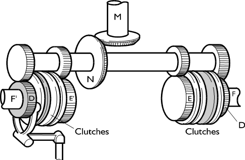
An engine-driven cross-shaft drives a series of gear sets, each one duplicated at either side of the vehicle, to which the drive to the tracks is connected using a corresponding series of clutches. If each gearbox is in the same gear, the vehicle will run straight; if different gears are selected on either side, it will follow a curve of a defined radius, provided the appropriate clutches are fully engaged. In this condition, the system is regenerative, since no power is dissipated by clutch slip. The power from the slower track is fed across to the faster via the cross-shaft. Since a definite turn radius is induced, the steering action is velocity controlled, rather than force controlled. This provides the driver with a predictable response to steer demands.
This system, being regenerative, is more elegant technically than the clutch-brake system. However, since steering results in an increase in tractive resistance, it is rarely practicable to steer by making an upchange at the outboard gearbox. Therefore the available turn radius depends, at any time, on the number of available gears lower than that currently engaged. This is contrary to the driver's requirements and means that, if the steering gearbox is also used as the change-speed gearbox, the vehicle cannot steer at all in bottom gear. Also, there is no locked-turn facility, unless an auxiliary brake is employed outboard of each steering gearbox.
Despite these limitations, geared-steer systems have been used on a number ofrecent Russian fighting vehicles. In the latter examples, the transmission is invariably a purpose-designed, integrated steer/change-speed unit. However some earlier examples have used standard commercial change-speed gearboxes with separate 'military special' steering systems.
Differential steering
As an alternative to geared steer, skid steering may be achieved by inter-connecting the right and left hand tracks via one or more differential gear sets, and inducing disparate track speeds by forcing rotation of the differential gears. The simplest means of achieving this is the braked differential. (Figure 3). If the brake on either output shaft is applied, that shaft will be slowed, forcing differential action and speeding up the other output shaft accordingly.
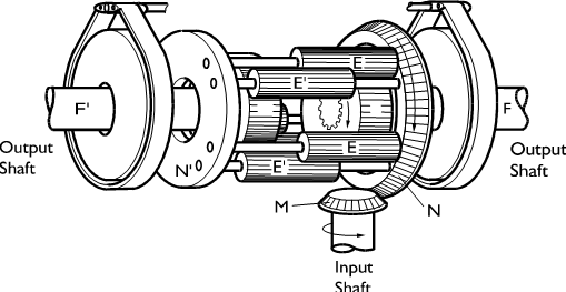
Like the clutch-brake system it offers force control. From the regeneration point of view, it is actually worse than the clutch-brake, since the slipping brake dissipates energy both from the engine and from the slowed track, unless the latter is locked completely.
However, this system is extremely simple - it can be based on a conventional wheeled vehicle axle, with the normal service brakes applied individually as steering brakes. Most wheeled agricultural tractors use this system to supplement the normal ackerman steer. Some military vehicle steer systems have been based on this type of commercial hardware.
Improved steering is offered by the controlled differential (Figure 4). A spur differential gear set has side gears S and S' which mesh with planets E and E' respectively. Extended planet spindles carry side gears C and C' which co-rotate with E and E'. These mesh respectively with gears D and D', which are mounted on free-running hollow shafts, concentric with the output shafts F and F', and carry brakes at their outer ends. In straight run, all the gears rotate en bloc, without relative movement. If one of the brakes is locked, this arrests the corresponding D gear, causing the associated C gear to precess around it, thereby inducing differential action between the two outputs.
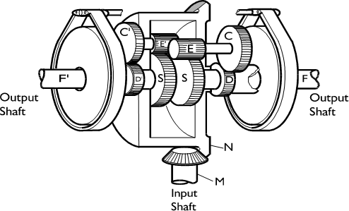
With a brake fully locked, this system gives a fixed turn radius (that is, velocity control) and is regenerative. However, it provides only a single steer ratio, unless the driver resorts to brake-slipping. This must inevitably offer a compromise between the tight turn radius, required for good low-speed manoeuvrability, and the much larger radius required to avoid lateral sliding or overturning of the vehicle at high speeds, as a result of centripetal forces. Such a compromise may be acceptable in a vehicle of modest performance, but becomes less so as demands for maximum speed and good manoeuvrability increase. Additional brakes are often provided on the output shafts, so that the differential steer ratio can be supplemented by a locked turn.
Controlled differential steering gearboxes have been available for a number of years as 'stand-alone' units, for use in conjunction with a standard change-speed gearbox. They have been supplied for both commercial and military tracklayers (for example, M113 &FV 430 series), notably by the Cleveland Tractor company in the United States under the name ‘Cletrac’, and have been used in conjunction with standard commercial change-speed gearboxes. However, the limited steering finesse and the poor packaging resulting from the use of separate change-speed and steering units, renders this arrangement unattractive for modern high performance fighting vehicles.
It would be possible to refine either system by using closed-loop control to detect track speed disparity and modulating the steer brake torque in response to driver demand for steer. This would effectively control brake slip proportionally to demand and thus achieve velocity-controlled modulation of steer radius. The steering would not, though, be fully regenerative in such conditions. An alternative refinement, which has already been offered as a retrofit for existing controlled differentials, is to connect the steering brake drums by steplessly variable hydrostatic drives [1]. This again offers velocity controlled variable ratio steer, but without dissipating energy on a slipping brake. Either method could offer a relatively simple, yet reasonably precise steering system, based on essentially commercial hardware.
Double differential systems
The double differential system, which was pioneered in France by Brillié and in the UK by Wilson, can provide a set of turn radii dependent on the forward gear in use and is a fully integrated change-speed/steer transmission (Figure 5).
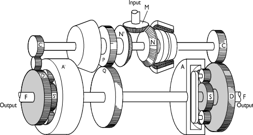
The input shaft drives two counter-rotating bevel gears N and N'. N' drives the change-speed pack, represented by gears P and Q in this simple diagram. In straight run, the upper cross-shaft is stationary, so that both output planet carriers, F and F', are driven around their respective stationary suns at equal speeds by the annuli A and A', from the change-speed pack. To steer, the cross shaft is driven in the appropriate direction by engaging one or other of the clutches beside bevel gears N and N', thereby driving the suns S and S' at the same speed, but in opposite directions. This causes the right and left-hand outputs of the two differentials to speed up and slow down (or vice versa) by equal amounts.
The result is a predictable track speed difference (that is, velocity control) for a given engine speed. However, the forward speed upon which this difference is superimposed depends on which change-speed gear set is engaged. Thus the proportional speed difference (that is, the track speed ratio), and therefore the radius of turn, is tightest in the lowest forward gear and increases progressively as higher gears are engaged. This confers good low speed manoeuvrability and yet reduces steering sensitivity and the risk of lateral sliding in the higher gears, in line with the requirements of 'g-limited' cornering at higher speeds.
The system also offers the possibility of pivot turns. If the change-speed outputs (A and A') are stationary (that is, gears in neutral), rotation of the cross shaft will cause contra rotation of the right and left hand suns, and thus equal and opposite rotation of the final output shafts, giving a true pivot turn about the vehicle axis. This is clearly of great benefit when manoeuvring big vehicles in confined spaces. However, if the resistances at the right and left side tracks are unequal, the main change-speed cross shaft will tend to auto-rotate, upsetting the generation of a pivot turn. Some designs obviate this by locking the change-speed cross shaft.
The double differential thus offers a good, velocity controlled, fully regenerative steer capability, in line with vehicle manoeuvrability and performance requirements. However, it will be apparent there is a direct arithmetic relationship between steer ratio and change-speed gear ratio. In vehicles with a maximum speed greater than about 45 km/h, this means that, in practice, the ratio spread required in the change-speed pack to achieve adequate performance does not give sufficient steer-ratio spread between high and low forward speeds. Also, if a vehicle is cruising at moderate speed in a high gear, at least one down-change may be needed in order to achieve what the driver might regard as adequate steering response.
A solution is to provide a variable ratio drive between the transmission input and steering cross shaft, enabling the latter to be driven faster relative to the input when the vehicle is travelling at slower speeds, thereby conferring greater manoeuvrability.
Many of the earlier transmissions to incorporate variable ratio cross shaft drive employed hydrostatic pump/motor units (Figure 6), giving stepless ratio variation and thus providing virtually, ‘car-like’ steering. Indeed, the pioneering Brillié system of the 1920’s used this technique.
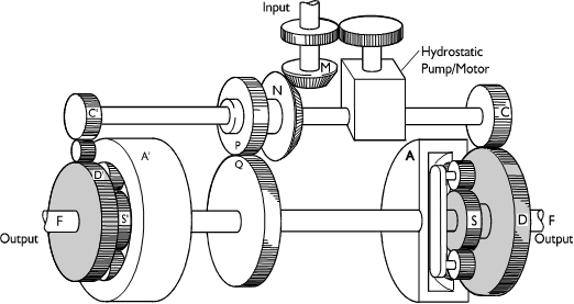
However, the modest efficiency of these hydrostatic systems leads to indifferent overall transmission efficiency and thus to heat-rejection problems. This has induced designers to question the operational necessity for such sophistication and refinement of steer control, and some more recent transmissions have abandoned stepless hydrostatic steer systems in favour of two or three stepped gear ratios to drive the cross shaft. Others (for example, ZF LSG200) use hydrostatic steer, supplemented by mechanical gearing for tight turns. This limits the hydrostatic power and thus the efficiency penalty.
Triple and quadruple differential designs have also been developed [1], mainly with the object of enhancing the range of available steer ratios for a given ratio range in the change-speed gearbox. The triple differential has been used quite extensively, especially for lighter vehicles, but the latter has not achieved series production.
The hydrostatic variable double differential transmission system clearly offers very sophisticated skid steer control, but requires considerable mechanical complexity to do so.
Until recently, the commercial skid steer market has been content with simple braked differential, controlled differential or clutch-brake systems. Commercial tracklayers generally have modest automotive performance requirements. There is therefore little danger of a high speed slide or capsize and a simple steer system can be designed to give reasonable low speed manoeuvrability. Any deficiencies in the latter respect can generally be overcome by the skilled and experienced operators of such equipment.
By contrast, the modern tracklaying fighting vehicle may have a top speed in excess of 80km/h on road and thus needs precise, sensitive, controllable high speed steering for safety both of the crew and other road users. Conversely, excellent manoeuvrability is required at lower speeds to meet tactical requirements for deployment in dense woodland and other restricted environments. These contrasting but equally exacting requirements may have to be accomplished by a driver in his teens, with no more than single figure driving hour experience, who has charge of a vehicle weighing more than 60 tonne, with a 1100kW (1500hp) engine and costing in excess of £2 million. Furthermore, he may have to drive cross-country at night without lights and, if the vehicle is operating 'closed down', he is limited to virtually tunnel vision through his armoured glass vision blocks.
Clearly therefore, everything possible must be done to ease the driver's task by minimising the skill required to control and manoeuvre his vehicle. This has lead not only to very sophisticated and complex steer systems, but also to virtually universal adoption of fully automatic change-speed transmission in current generation vehicles, in contrast to commercial practice.
Commercial/military cross fertilisation
Commercial and military performance requirements and design solutions have thus diverged considerably in recent years and this has lead to the development of wholly 'military special' transmissions, at least for heavy vehicles such as main battle tanks, self-propelled artillery guns and some infantry fighting vehicles. Though designed to be as compact as possible, these transmissions often occupy more precious under-armour space than the engine. The transmission may well cost more than the engine, notwithstanding that the latter is also a 'military special' ofperhaps threeor fourtimes the specific output ofa commercial unit.
The current UK tank transmission (Figure 7), which is reasonably representative of the extant ‘state-of-the-art', has a torque converter and six speed epicyclic automatic change-speed transmission, with a hydrostatic steer system and includes oil-immersed main vehicle brakes. It has a weight of nearly 2.4 tonne and a box volume (length x breadth x height) of just over 2m3.
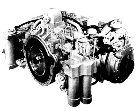
Apart from the torque convertor and items such as bearings, seals and filters, it employs few major proprietary off-the-shelf components. The hydrostatic steer system operates at about three times the pressure of commercial systems in order to secure maximum compactness.
Such units provide formidable technical challenges for the transmission engineer in rising to the users' requirements. However it is becoming increasingly apparent, to both the user and the provider, that further development along these lines is commercially untenable, especially in view of the dwindling sales volumes for which the major suppliers are competing ever more aggressively.
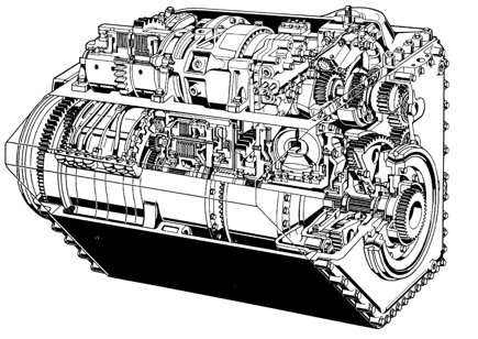
There is limited availability of commercial hardware at the heavier end of the market, where power throughputs, sufficient to meet the higher military requirement, are so much in excess of civilian requirements. However, one manufacturer has tackled the problem by employing the principle of modular design to enable the same basic transmission to be adapted easily for different vehicle installations and facilitate the employment of common internal modules across a range of power requirements (Figure 8).
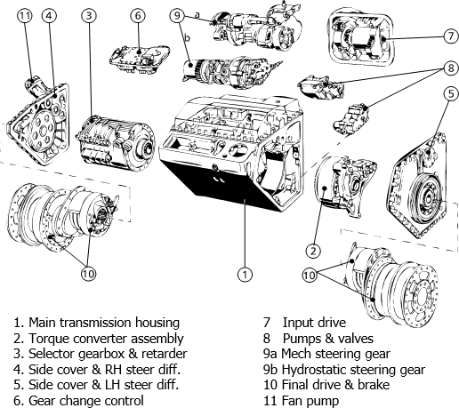
The modular approach also greatly simplifies assembly and repair. Standard commercial hydrostatic units are employed but, by careful attention to packaging and spatial design, the additional bulk has been absorbed without detriment to overall compactness (Figure 9).
Smaller vehicles such as personnel carriers, missile platforms and reconnaissance vehicles weighing between about 12 and 25 tonne and having engines of 250-450kW (350-600hp) are clearly closer to commercial practice. Indeed, because of the much shorter life requirement and lighter duty cycles in the military environment, it is often possible to up-rate considerably such items as change-speed packs. However, this military exploitation of commercial hardware has not been as widespread as might be expected, because relatively few suitable automatic or semi-automatic heavy commercial transmissions have been available until quite recently.
Early exceptions can be found in transmissions produced by Alvis Transmissions (formerly Self Changing Gears), who, for many years, made commercial epicyclic gearboxes based on the Wilson compounding principle. This company has produced several military transmissions based on its RV28 bus gearbox, including the TN26 fitted in the current UK Combat Engineer Tractor.
However, none of these includes a steering mechanism. Though the idea of transplanting a commercial change-speed gear set into an integrated tracked vehicle transmission is attractive, it is difficult to implement in practice because of the disparity in basic layout. Most commercial change-speed gear sets have the input and output coaxial at opposite ends, whereas, in a track steer transmission, the change-speed set is normally driven from the side, with outputs to the steering differentials at both ends. Also, few commercial gearboxes offer the ratio spread required for military tracklayers.
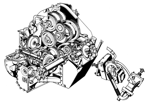
One successful exception is the ZF LSG1000 transmission for lightweight military tracklayers. This uses the change-speed pack from the company's WG range of transmissions for earth moving vehicles (Figure 10), to which is added a hydrostatically driven double differential steering set.
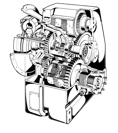
Both the parent transmission and its progeny are of rather unconventional shape and several transfer gears have had to be added in order to produce the latter. However, as with other recent ZF transmissions, good packaging and detail design result in reasonable specific bulk (Figure 11).
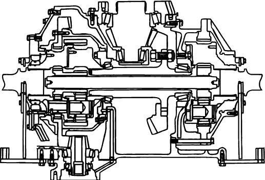
Though transmissions for civilian track-layers in the agricultural and construction fields have traditionally lagged well behind their military counterparts technically, Caterpillar has developed a variable steer ratio double-differential system for its Challenger 65 tractor (Figure12). This vehicle is marketed to compete with conventional wheeled tractors, yet offers much lower ground pressure. The sophisticated transmission has been provided in order to give comparable manoeuvrability and 'feel' to a wheeled tractor, and thus facilitate driver acceptance. No application has yet emerged to the authors' knowledge. However, this system appears suitable for use in light military tracklayers. However, it seems unlikely that there would be a demand for heavier civilian transmissions of this type, so that the potential for direct civilian-to-military cross application for vehicles such as main battle tanks is minimal.
The future
Aside from commercial considerations, many current military tracklayer transmissions suffer a serious shortcoming in terms of efficiency. Full load efficiencies around 80% are achievable. The main sources of power loss are drag at disengaged clutches or brakes in the change-speed pack and their associated idling planetary gears, and the hydrostatic steering elements. Whilst efficient energy utilisation is always important, the fuel consumption penalty resulting from transmission inefficiency is not of paramount significance in the military environment. Of much greater importance is the increased under-armour volume resulting firstly from the need for a larger engine to realise a given net sprocket power, and secondly from the increase in radiator volume and fan power to deal with the transmission losses. Both contribute significantly to an upward spiral in vehicle weight and volume for given performance and armour protection levels.
In the commercial vehicle world, good transmission efficiency is important for its direct effect on fuel consumption and the economics of operation. Though commercial automatic transmissions generally achieve efficiencies of a higher order than their more complex military counterparts, the fuel consumption penalty relative to a manual transmission has precluded wider acceptance.
There is clearly a need, for different reasons, in both the specialised military and general commercial environments, to improve the efficiency of automatic transmissions and, in the military world in particular, to reduce specific bulk. Though the driving force of ultimate performance is perhaps more pressing in the military world, the escalating cost of development and shrinking production volumes increasingly preclude development of new hardware solely for military transmissions. However, a number of recent advances, which have been brought to technical fruition in transmissions for the civilian market, could well be exploited to produce more efficient and compact military tracked vehicle transmissions.
One such is the 'twin layshaft' automatic gearbox which has been under development for some years by Automotive Products [2], and more recently, introduced by Porsche as an option on its high performance cars. This delightfully simple and ingenious concept (Figure13) provides automatic drive take-up and hot shift using only two clutches, irrespective of the number of gears. It therefore offers inherently excellent efficiency.

A similar concept, but using two auxiliary friction clutches for gear change speed synchronisation (instead of synchromesh devices on the gears) was produced, in prototype form, for a military application by David Brown, working under contract to the UK MOD.
It is considered that either of these concepts could form a suitable basis for joint development of a new commercial vehicle gearbox and a military tracklayer transmission using the same change-speed pack. The basic concept is sufficiently flexible to accommodate differing installation requirements. The technical risk is low and there are potential benefits in efficiency and specific bulk, compared to conventional automatics. This line of development is considered to offer a good opportunity for technical and commercial advantage over manufacturers who cling to epicyclic transmissions. It could be that this would offer an opportunity for joint government/private venture funding of development.
For track steering, the variable ratio double differential skid steer system is without peer in terms of performance. Some manufacturers have already drawn back from steplessly variable hydrostatic systems, in the quest for better efficiency, by employing two or three stepped gear ratios in the steer drive.
An attractive alternative, which would restore the fully progressive steer of the hydrostatic system, would be to employ traction drive variators to drive the steering cross shaft. The steel belt type has been in volume production for some time for passenger car automatic transmissions [3]. The Hayes-Perbury type, though not yet in series production, has achieved technical maturity. In the shunted configuration with 'geared neutral' as perfected by Torrotrac [4], it would be particularly suitable for driving the cross shaft of a double differential steer system. Either option could offer a military transmission manufacturer the opportunity for innovation by drawing on advanced commercially developed technology.
The traction variator might also be more attractive for military applications than in the commercial sector as a main drive element. A steplessly variable transmission using shunted hydrostatic variators is already in series production by General Electric in the USA for medium-weight military tracklayers [5]. The use of traction variators in a similar manner has the potential to offer superior efficiency and reliability, and again offers the opportunity to transfer new commercial technology to the military sector [6,7]. However, the restricted ratio spread of this type of variator would undoubtedly require range-change gearing for military applications.
Whatever type of steering drive is used, it would be technically feasible, and may prove commercially attractive, to synthesise a double differential steering system from commercial elements.
Figure 14 shows a possible layout. The engine drives a commercial change speed gearbox whose output is taken to a cross shaft providing the main input to the steering differentials. A hydrostatic pump is also driven from the engine. The output from this pump powers a motor that drives the steering cross shaft. These hydrostatic units could again be commercial ‘off-the-shelf’ hardware. Alternatively, mechanical variators or electric motors could be used to drive the steer shaft.
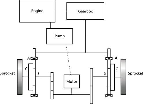
Figure 15 shows an alternative arrangement whereby the steering input to each of the double differentials is via a separate motor. The two motors would contra-rotate to provide steer.
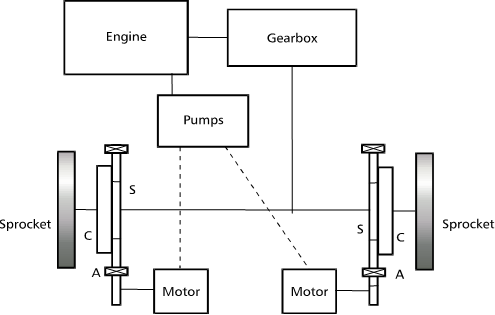
In this instance, power regeneration during steer would be carried out hydraulically (or via electrical or mechanical variators, if used). This would necessitate much larger machines to handle the regenerative power, but might prove attractive for applications requiring particular finesse of steering control at low speed for operations such as bulldozing. The two steer motors could also be used in unison, either in forward or reverse to provide fine speed control in such circumstances. In this mode, the system could be controlled by a single ‘joy-stick’, allowing the driver to effect forward/reverse and steer, continuously variable over the operating range. In normal road and cross-country driving, the gearbox would be used for tractive power throughout and the hydrostatic systems solely for steering.
Any such systems that were synthesised from commercial hardware elements would be unlikely to match the specific bulk of purpose-designed, integrated, change-speed / steer transmissions. However, the reductions in both development and unit cost production cost could well be considered an attractive counter to the increased bulk – at least for some applications. Studies have shown that suitably rated commercial hardware is available to meet the needs of light and medium weight armoured vehicles.
There is widespread current interest in electric transmissions for military tracklayers [8,9]. Effort is being concentrated on developing the control technology to permit the latest advances in electric motors to be applied to vehicle propulsion and skid steering.
Electric drive systems offer the potential for electric power regeneration during steer, and provide great flexibility in the overall layout of the power train. However, electrical regeneration demands very high power ratings for the motors, and some designers [9] have retained the double differential layout, with the change-speed gearbox and mechanical or hydrostatic drive replaced by electric motors.
The cost of suitable high performance electric motors is currently very high. However, intensive development of traction motors for civilian vehicles could provide a more reasonably priced source for the military sector. Motors for commercial and public service vehicles would be of suitable rating for lighter tracked military vehicles.
Conclusions
There is some indication of a narrowing of the gap between the technology of transmission systems for commercial vehicles and the highly sophisticated ones needed for fast military tracklayers.
Falling production volumes and rising development costs mayforce military transmission engineers to rely increasingly on commercially based sub-systems, at least for light and medium weight vehicles. Because of the converging performance requirements and these commercial pressures, much potential is seen for technology transfer between the commercial and military fields, and for joint development programmes for transmissions using common elements. The availability in the commercial sector of both automatic stepped ratio gearboxes and stepless mechanical and electrical variators of suitable ratings is likely to increase over the next few years, thus facilitating this approach.
The successful prosecution of such ventures will necessitate a greater willingness to innovate and invest than has been demonstrated by UK transmission manufacturers in recent years. A fruitful route might be jointly funded development between the commercial sector and governments of the interested nations. The industrial sector of alone is unlikely to be willing to invest the necessary resources to develop the type of specialised transmissions required for the future AFVs, in view of low production numbers and a corresponding low return on investment. Both design expertise from the commercial sector and the adoption of developed commercial hardware, already in volume production, could expedite the successful implementation of joint public/private venture projects. However, to achieve fruitful results, government ministries and agencies will need to adopt more proactive, innovative and less adversarial procurement strategies.
References
[1] B. Jones, Steering Mechanisms, Military Vehicle Technology (MSc) Course Notes. RMCS, 1993.
[2] H. Webster, Fully Automatic Vehicle Transmission using a Layshaft Type Gearbox, SAE Paper 810104.
[3]D. Hahne, "Continuously Variable Automatic Transmission for Small Front Wheel Drive Cars", Proceedings of the Institution of Mechanical Engineers, C2, 1984.
[4] C. Greenwood, "The Design, Construction and Operation of a Commercial Vehicle Continuously Variable Transmission", Proceedings of the Institution of Mechanical Engineers, C11, 1984.
[5] R. Ftio, "XMI Hydromechanical Transmission", Automotive Industries, Jan 1971.
[6] B. Jones, S. McGuigan, and P. Moss, Transmission Concepts for Future Tracked Fighting Vehicles, RMCS Report DG/0304/001, 1984 (Commercial-in- Confidence)
[7] A. Topp, Design of an Integrated Continuously Variable and Steering Transmission for Light Tracked Vehicles, RMCS MSc Project Report, 1989.
[8] R. Hare and A. Loss, "Electric Drives for Modern Combat Vehicle", International Defense Review, 3, 1990.
[9] H. Naunheimer, "Electric Drive Technology for Tracked Vehicles", Journal Battlefield Technology, Vol. 1, No 2, Jul 1998.