
Volume 1, Number 3, November 1998
Long Rod Penetrator Performance
Abstract
Simple models for the internal, external and terminal ballistics of a tank gun firing a long rod penetrator are described and used to determine the penetration that can be achieved for a typical system. The models also show the effect on penetration of modifications to the penetrator geometry, charge parameters and barrel length. The results show that there are many interdependencies, and that an apparently simple modification to improve penetration may be accompanied by unacceptable consequences elsewhere, particularly high breech pressure and sabot stresses, and an inappropriate all-burnt position. It is also shown that these effects can only be mitigated by further modifications which tend to negate the apparent improvement. The most promising improvement in penetration is based on more energetic propellant and is about 12%.
Introduction
The primary target for a tank gun is heavy armour, and the performance of such guns is generally quantified by a combination of hit probability and armour penetration. This performance has shown steady improvement over a number of years for two main reasons. First, the development of sophisticated fire and gun control systems has increased the hit probability. Second, penetration has increased by the introduction of the long rod penetrator, with a target strike velocity sufficient to initiate hydrodynamic, or liquid-like, behaviour of both the penetrator and the target material. This paper is concerned with the second of these two reasons; that is, with penetration, given that a hit has already occurred.
Hydrodynamic penetration is a complex mechanism which begins to appear when the strike velocity exceeds a critical value, typically about 1,150m/s for current penetrators against rolled homogenous armour (RHA) targets. Full hydrodynamic behaviour does not occur until the strike velocity reaches several kilometres per second, such as occurs with shaped charge munitions [1]. At strike velocities less than about 1,150m/s penetration of metal armour occurs mainly through the mechanism of plastic deformation.
A typical penetrator achieves a strike velocity around 1,500m/s to 1,700m/s, depending on range, and therefore target effects generally exhibit both hydrodynamic behaviour and plastic deformation.
A number of models of varying degrees of complexity have been developed [2,3] to predict long rod penetrator performance. A common feature that emerges from these models is the importance of a high strike velocity to exploit more fully the hydrodynamic penetration mechanism, which, in turn, is further improved by the use of longer penetrators having higher densities relative to the target material density. This is amply supported by experimental work [4,5]. Empirical constants are generally included in the models to allow for the less-than-complete hydrodynamic behaviour.
First thoughts suggest that continual improvements in penetration by means of higher strike velocities with ever longer and more dense penetrators might be relatively easy to achieve. However, more careful thought shows that these features interact with each other, and with other important factors such as the internal and external ballistics, the forces on both the ammunition and the gun, and the ammunition stowage and handling. Consider, for example, just some of the consequences of an increase in penetrator length with all other gun and most ammunition parameters remaining unchanged:
- Penetrator surface area will increase giving an increase in drag and a reduction in strike velocity.
- Penetrator mass will increase so that for the same amount of useful energy extracted from the propellant the muzzle velocity and hence strike velocity will decrease.
- A longer penetrator will probably need a longer sabot for in-bore support, further increasing the round mass, and the drag due to the increased length of the threaded portion of the penetrator.
- The lower muzzle velocity implies a longer shot-in-bore time, which will lead to a faster propellant burn and a higher peak pressure.
- A higher peak pressure will lead to higher stresses in the barrel, the sabot and the penetrator.
- A longer penetrator will require more stowage space and more space behind the breech for handling.
Quantifying the effects of such modifications on penetration is therefore not quite so straightforward as some of the predictive penetration models might suggest. There would also need to be careful examination of the effects of such modifications on other parts of the complete gun system.
The following sections describe briefly simple models for the terminal, internal and external ballistics, and use hypothetical but credible data for a tank gun system to show how some of the various interactions can be studied and quantified.
Terminal ballistics model
The simplest theory for the hydrodynamic penetration of a long rod, Figure 1, is almost identical to that for a shaped charge [6].
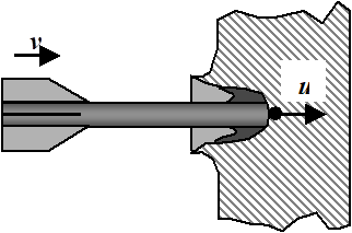
During hydrodynamic penetration the velocity of the rear of the penetrator, v, is assumed to be constant and equal to the strike velocity; the crater growth rate, u, is also assumed to be constant.
Equating pressures at the penetrator/target interface and using Bernoulli’s equation gives:
(1)
where ρp is the penetrator density and ρt is the target density.
Assuming the penetrator is completely eroded in the same time as that for the crater to grow:
(2)
where L is the penetrator length; P is the penetration depth.
Rearranging Equations 1 and 2 gives the well known penetration equation:
(3)
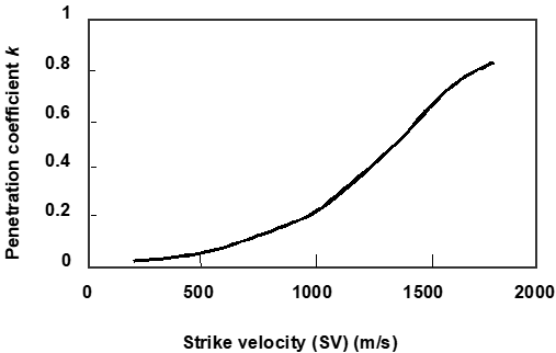
Because the strike velocity is limited, the penetration mechanism is not completely hydrodynamic. It is common practice to allow for this by means of a velocity dependent coefficient, k, [4] to give:
(4)
For example, a tungsten-nickel-iron penetrator with a density of 16,500kg/m3 striking a steel target with a density of 7,865kg/m3 at a velocity of 1,600 m/s, the value of k is about 0.65, giving a penetration approximately equal to the penetrator length. It should be noted though that, contrary to the impression often given, this is not a fundamental rule, rather a coincidence of today’s technology.
It is clear from Equation 4 that penetration can be improved by increasing penetrator length, L, penetrator density, ρp, or strike velocity, v, and hence the coefficient, k. However, as already indicated, such changes will almost certainly have implications for other parts of the weapon system.
External ballistics model
The performance criterion has already been stated to be penetration, and, because this is dependent on strike velocity, the external ballistics model need consider only the effects of atmospheric drag and gravity. The issue of stability is not included. Tank guns trajectories are relatively flat and hence the effects of variations in atmospheric conditions with altitude are commonly ignored. Engagement ranges are generally small, seldom more than 3,000m, so that flight times are short, less than 2s, and hence earth curvature and rotation effects can also be ignored. With these assumptions the motion of the penetrator can be modelled as a point mass subjected to two forces, namely, its own weight acting vertically downwards and a drag force acting at a tangent to the trajectory (Figure 2).
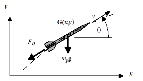
The total drag force, FD, can be considered as the sum of a number of components (Figure 3). The excrescence drag is due to the threaded portion of the penetrator associated with the sabot.
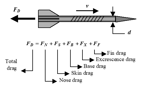
Each drag component has the form:
(5)
where ρ is the air density, CDis the drag coefficient, which is generally expressed as a function of Mach number, d is the penetrator diameter and v its velocity.
The equations of motion for the projectile thus become:
where mp is the projectile mass, and x, y and θ are as defined in Figure 2. Equations 6 can be solved numerically to give the trajectory, and the projectile velocity, v, and its direction, θ, throughout its flight.
Internal ballistics model
The internal ballistics calculations are based on the classical lumped parameter model [7], which assumes that the behaviour of the gas in the barrel during combustion and expansion can be described in terms of mean gas properties and their rates of change. This assumption becomes more valid towards shot exit, and hence is quite adequate for the prediction of quantities such as muzzle velocity and peak chamber pressure.
Propellant combustion is assumed to follow Piobert’s law; that is, all surfaces burn inwards at the same rate at any instant in time. It follows that combustion ends when the shortest distance between two opposing faces, the ballistic grain size, D, has reduced to zero. The burning rate is defined by the fraction f of D remaining at time t, and is a critical function of pressure, p:
(7)
where α and βare constants related to the chemical composition of the propellant.
The mass fraction of propellant burnt, z, is related to the fraction of the ballistic size remaining, f, by the geometry of the propellant grains which is defined by its form function, c, a semi-empirical constant:
(8)
The energy released by propellant combustion can be accounted for by the energy balance given in Equation 9:
(9)
where E is energy and the suffixes refer to:
p propellant r gun recoil KE
s shot KE q residual heat in gases
g gas KE ε barrel strain energy
µ shot friction u unburnt propellant KE
The energy terms in Equation 9 can be determined from various theoretical and empirical relationships.
Finally, the equations of motion for the shot in the barrel are:
(10)
where:
Ab is the bore cross sectional area
ps and pa are the shot base and atmospheric pressures respectively
Ri is the shot resistance to motion
m is the combined mass of the penetrator and sabot
v and x are the shot velocity and displacement in the barrel
Equations 7 to 10 can be solved numerically to give, in this particular study, the muzzle velocity, maximum chamber pressure and shot motion. From the latter, an indication of the maximum sabot stress based on the shear area over the threaded portion can be determined. This is subsequently referred to as the nominal sabot shear stress. The pattern of stresses in the sabot and penetrator during the internal ballistics phase is clearly much more complex than this, but it is considered adequate for showing the trends in this study.
SAMPLE DATA
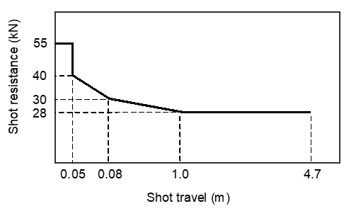
The initial data for the example described in the following section is shown in Table 1, and in Figures 4 and 5.
| Gun | ||
|---|---|---|
| Chamber volume | m3 | 0.0083 |
| Bore db | mm | 105 |
| Shot travel, xs | m | 4.7 |
| Recoiling mass | kg | 2000 |
| Penetrator | ||
| Diameter, d | mm | 25 |
| L/d ratio | 16 | |
| Density, p | kg/m3 | 16500 |
| Drag Coefficients | ||
| Nose | 0.044 | |
| Skin | 0.055 | |
| Base | 0.044 | |
| Excrescence | 0.063 | |
| Fins | 0.180 | |
| Sabot | ||
| Length/pen length, Ls/L | 0.760 | |
| Mean dia/bore, ds/db | 0.500 | |
| Density, s | kg/m3 | 2710 |
| Charge | ||
| Mass, mc | kg | 6.700 |
| Type | Stick | |
| Force constant, F | MJ/kg | 0.951 |
| Ratio of specific heats | 1.260 | |
| Density | kg/m3 | 1167 |
| Burning rate coeff, | 0.16810-8 | |
| Burning rate index, | 0.993 | |
| Ballistic size, D | mm | 1.50 |
| Form function, c | 0.190 | |
| Target | ||
| Range | m | 1000 |
| Super-elevation | m | 2 |
| Density, t | kg/m3 | 7865 |
RESULTS FROM SAMPLE DATA
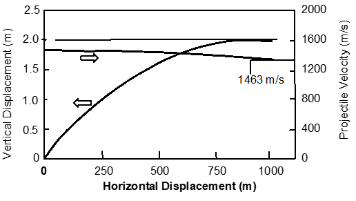
The results of running the sample data through the model are shown in Figures 6 and 7, and in Serial 1 of Table 2.
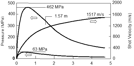
In Figure 6 the muzzle velocity is seen to be 1,517m/s with the all-burnt position, AB, at 1.57m, which represents about 33% of the shot travel, a maximum breech pressure, pb max, of 462MPa, and a nominal sabot stress, τs nom, of 63MPa. These values are deemed to be acceptable.
In Figure 7 the effect of drag on the projectile is seen to reduce the strike velocity, (SV), to 1,463m/s, and hence a penetration constant of k = 0.61 is obtained by interpolation from Figure 5. Equation 4 then gives the penetration achieved, p, of 353mm, which is nearly 90% of the penetrator length.
The sample data and results are summarised in Serial 1 of Table 2. An asterisk (*) by a subsequent Serial indicates a solution which is considered acceptable, that is, with stress levels and an all-burnt value not significantly different from those obtained from the sample data.
Effects of some possible modifications
The models described, and associated software, allow many possible modifications to be investigated, but in this report discussion is restricted to those that are more commonly suggested, often without adequate analysis.
Equation 4 indicates unequivocally that penetration is proportional to penetrator length and hence a longer penetrator seems a good place to start when looking for improvements.
The length to diameter ratio in the sample data is 16, which is quite modest by modern standards. An increase to 20 would not be at all unreasonable and, at first sight, would suggest that there should be an improvement in penetration of 25%; that is, from 353mm to more than 440mm.
Increased penetrator length
The results of running the model with this increased penetrator length, keeping everything else constant, are shown in Serial 2 of Table 2. (Note that entries in Table 2 are only made where the data has changed.) Far from the expected 25% increase in penetration, less than half this is achieved. The reason is not hard to establish. The increase in penetrator length leads to a proportional increase in both penetrator and sabot mass, the latter because the sabot length is automatically increased in the model to give adequate penetrator support. This increase in mass reduces the in-bore acceleration, leading to a reduction in muzzle velocity from 1,517m/s to 1,436m/s. This, together with the small but measurable increase in drag resulting from the longer penetrator, gives a reduced strike velocity of 1,392m/s, and hence reduces the penetration constant, k, to 0.546.
The lower in-bore acceleration leads to more rapid combustion, a higher maximum breech pressure, which is probably unacceptable, and an associated earlier all-burnt position. Because the sabot length is defined as a proportion of the penetrator length there is no significant effect on the sabot nominal shear stress, but it must be emphasised that this is a very simplified picture of what, in reality, is a very complex stress situation. In addition to these objections there may be problems with handling and stowage of the longer penetrator.
A more realistic approach might be to take a more modest increase in penetrator length to diameter ratio, and simultaneously to decrease both penetrator diameter and sabot profile (defined by mean sabot diameter) to maintain their respective masses. Because the mass depends on the square of the diameter but only linearly on the length, the reductions in diameter are not large. The internal ballistics are unchanged. The effect on the total drag of the increase in penetrator length and reduction in diameter almost cancel, leaving a small but useful increase in penetration of about 8.5%. The details are shown in Serial 3 of Table 2. The question of penetrator strength and stiffness, and sabot strength, would, of course, need to be checked.
An alternative approach is to take the original increase in length to diameter ratio of 20 (Serial 2) and to overcome the problems by suitable modifications to the charge. Essentially, the requirement is to slow down the combustion, and hence reduce the maximum breech pressure, whilst maintaining the work done during the internal ballistics phase. One possible solution is to increase the ballistic grain size, D, from 1.5mm to 1.6mm, reduce the form function coefficient, c, from 0.19 to –0.03 by means of a more progressive propellant (using a multi-tube form or surface combustion suppressants), and by increasing the charge mass, mc, from 6.7kg to 7.1kg. These changes are primarily associated with propellant geometry, not chemical composition, and give an acceptable solution with a penetration of 389mm (Serial 4) an increase of just over 10% on the initial sample data (Serial 1).
It is clear, therefore, that improvements in penetration derived from a longer penetrator are not as great as might initially be thought, although the nature of such modifications might be considered a practical proposition.
Increased Barrel Length
It is clear from Figure 6 that there is a significant pressure in the barrel just before shot exit and hence a longer barrel might be expected to allow the adiabatic expansion that occurs after the all-burnt position to continue and to give a higher muzzle velocity, with all the attendant advantages. The disadvantages are an increased equipment weight, a change in the location of the ordnance centre of gravity which will affect balance, more barrel droop, and possible mobility implications due to an overall increase in vehicle length. Some of these disadvantages might be reduced by relocating the trunnions, but this entails major hardware modifications which are unlikely to be received favourably.
The effect of increasing the barrel length by 0.5m is shown in Serial 5, with an increase in penetration of less than 4%. Note that although the all-burnt position will be unchanged in absolute terms, as a proportion of the barrel length it will be a little closer to the breech. There may, therefore, be some scope for slowing the combustion rate a little, whilst maintaining the pressure levels, in a somewhat similar manner to that used in the modification based on a longer penetrator.
Increased Charge Mass
Increasing the mass of propellant, mc, within the same chamber size will result in a greater energy release and hence a higher muzzle velocity. The result of a 5% increase is shown in Serial 6 of Table 2. Although there is a useful increase in penetration the reduced void volume in the chamber leads to more rapid combustion, an earlier all-burnt position and higher pressures. The pressure can be brought down to an acceptable level by increasing the ballistics grain size to 1.6mm, but then more than half the gain in penetration is lost, Serial 7. The rather late all-burnt position could be exploited by the use of a longer barrel, if this is acceptable, recovering some of the lost penetration. The net result is a 7% increase in penetration (Serial 8). It should be noted though that more propellant is likely to lead to more rapid barrel wear, and there may be stowage implications due to the greater charge volume.
More Energetic Propellant
A modest increase in the force constant of the propellant would not be difficult to achieve, albeit at the cost of higher flame temperature and an increased barrel wear rate. Serial 9 shows this effect for a 10% increase in propellant force constant. Although the consequences are similar to that when using 5% more propellant (Serial 6), the improvement in penetration is considerably greater. Once again, slowing the burn rate, and lengthening the barrel enables most of this gain to be retained (Serial 10) giving a 12% increase in penetration.
Reduction of sabot mass
If the sabot mass can be reduced, say, by using a less dense material, without loss of strength, then the in-bore acceleration will be higher, even though the maximum pressure will be less. Serial 11 shows this effect for a 20% reduction in sabot density. By increasing the burn rate to make full use of the allowable breech pressure, a useful increase of 8% in penetration is now achieved (Serial 12).
| Serial | d mm | L/d ratio | Ls/L | ds/db | s kg/m3 | mc kg | F MJ/kg | c | D mm | xs m | AB % | pb max MN | s nom MN | MV m/s | SV m/s | k | P mm |
|---|---|---|---|---|---|---|---|---|---|---|---|---|---|---|---|---|---|
| 1* | 25 | 16 | 0.760 | 0.500 | 2710 | 6.7 | 0.951 | 0.19 | 1.5 | 4.7 | 33 | 462 | 63 | 1517 | 1463 | 0.610 | 353 |
| 2 | 20 | 22 | 571 | 63 | 1436 | 1392 | 0.546 | 395 | |||||||||
| 3* | 24 | 18 | 0.462 | 33 | 462 | 63 | 1517 | 1466 | 0.610 | 383 | |||||||
| 4* | 25 | 20 | 0.500 | 7.1 | -0.03 | 1.6 | 30 | 465 | 52 | 1425 | 1382 | 0.537 | 389 | ||||
| 5* | 16 | 6.7 | 0.19 | 1.5 | 5.2 | 30 | 462 | 63 | 1544 | 1489 | 0.634 | 367 | |||||
| 6 | 7.04 | 4.7 | 28 | 555 | 73 | 1581 | 1525 | 0.667 | 386 | ||||||||
| 7 | 1.6 | 40 | 463 | 64 | 1537 | 1482 | 0.627 | 363 | |||||||||
| 8* | 5.2 | 35 | 463 | 64 | 1564 | 1508 | 0.651 | 377 | |||||||||
| 9 | 6.7 | 1.05 | 1.5 | 4.7 | 27 | 566 | 73 | 1619 | 1562 | 0.703 | 407 | ||||||
| 10* | 1.6 | 5.2 | 35 | 467 | 65 | 1601 | 1544 | 0.685 | 397 | ||||||||
| 11 | 2168 | 0.951 | 1.5 | 4.7 | 40 | 423 | 64 | 1547 | 1493 | 0.636 | 368 | ||||||
| 12* | 0.14 | 1.4 | 31 | 467 | 65 | 1573 | 1518 | 0.660 | 382 |
Discussion and conclusions
A number of possible modifications to a hypothetical 105 mm tank gun and its ammunition have been investigated using simple models for the internal, external and terminal ballistics. The improvement criterion has been penetration.
The acceptability of possible solutions has been based primarily and quantitatively on simple calculations for the maximum breech pressure, the all burnt position and a nominal sabot stress, but consideration has also been given to some qualitative criteria. For example, some of the modifications, such as those to propellant geometry might be considered relatively simple to achieve. Others, such as those involving the quantity or type of propellant, and the penetrator dimensions are likely to be less simple and may well have stowage and handling implications. Yet others, notably changes to barrel length, would probably require major changes to the installation, and are unlikely to be acceptable.
The results show clearly the interdependence between the various gun and ammunition parameters, and the penetration that can be achieved. Changes to one parameter may suggest that an increase in penetration is easily achieved, but consequential effects of the change during the internal ballistics phase frequently lead to unacceptable pressure and stress levels. In a similar manner, consequential effects during the external ballistics phase often show that the improvement is less than might be expected. In practice, any one particular modification must be accompanied by several other modifications to give an acceptable solution.
None of the acceptable solutions investigated gives a large improvement in penetration. The most promising solution gives an improvement of about 12%, and is based on a more energetic propellant in combination with a longer barrel, together with some small changes to the propellant geometry (Serial 10). The next best solution of those examined is based on a longer penetrator, an increased charge mass and a significantly more progressive burn (Serial 4) giving an improvement in penetration of about 10%.
References
[1] A. Doig, "Some Metallurgical Aspects of Shaped Charge Liners", Journal of Battlefield Technology, Vol. 1, No. 1, pp. 1-3, Mar 1998.
[2] A. Tate, "A Theory for the Deceleration of Long Rods After Impact", International Journal of Mechanical Science, Vol. 19, pp. 121–3, 1977.
[3] W. Walters & J. Majerus, Impact Models for Penetration and Hole Growth, US Army Ballistic Research Laboratory Technical Report No ARBRL-TR-02069, Aberdeen Proving Ground, Maryland, May 1978.
[4] V. Hohler & A. Stilp, "Penetration of Steel and High Density Rods in Semi-Infinte Steel Targets", Proceedings Third International Symposium on Ballistics, Karlsruhe, Germany, 1977.
[5] V. Hohler and A. Stilp, "Study of the Penetration Behaviour of Rods for a Wide Range of Target Densities", Proceedings Fourth International Symposium on Ballistics, Monterey, California, 1978.
[6] M. Held, "Hydrodynamic Theory of Shaped Charge Jet Penetration", Journal of Explosives and Propellants, Vol. 9, pp. 9-24, 1991.
[7] Textbook of Gunnery and Ballistics, Vol. 1, HMSO, London, pp. 235-255; 1987.