
Volume 1, Number 2, July 1998
Comparison of the External Expansion of a Pressurised Thick-Walled Cylinder with Predictions from a Finite Element Model
Abstract
This paper compares the external expansion of a thick-walled test cylinder manufactured from EN1A free-cutting, mild steel, when subjected to an internal pressure with that of a simulated autofrettaged thick-walled cylinder cross-section, using finite element (FE) analysis. The results produced by FE are also compared with the conventional approach used for evaluating external strain in a thick-walled cylinder. This paper assumes kinematic material hardening (bilinear and multilinear) characteristics with Bauschinger effect. Comparison of results shows that those results produced by FE analysis are in good agreement with experimental results. The paper also highlights the appearance of Luder's band (stretch marks) on a thick-walled cylinder, due to plastic yielding.
Notation
Di = internal diameter;
Do = external diameter;
Y = yield strength (257.66 MPa for EN1A mild steel);
k = (Do/Di) wall ratio of thick-walled cylinder;
Dn = diameter of elastic-plastic interface;
n = Dn/Di ;
Po = autofrettage pressure;
Em = Young's modulus (210 GPa for EN1A mild steel);
Et = tangent modulus (3.69 GPa for EN1A mild steel);
b = correction factor (1.11 determined semi-empirically from the analysis of experimental autofrettage results on gun tubes);
Introduction
In mechanical design, some form of strength analysis is usually required as a part of the design process. Traditionally, this has been done by simple engineering calculations, involving the Tresca criterion. Autofrettage is a technique frequently used on gun barrels in order to produce a favourable residual stress field. In gun barrels, a variety of solutions for autofrettage have been developed by simplifying the assumptions used in the development of a mathematical model. Analytical solution of thick-walled cylinders becomes complicated because of the non-linear stress-strain relation. Stress, being an internal phenomenon, is also difficult to interpret in physical terms. More often, it is the strain that is measured physically and then translated in terms of stress to analyse the strength of the structure. Moreover, a gun barrel's strength, or depth of autofrettage, can be estimated from the external expansion of the barrel when pressurised internally.
As a thick walled cylinder is pressurised the bore material, which is the most highly stressed part of the cylinder, begins to yield. With further increase in pressure the yield surface begins to propagate through the thickness of the vessel, until it reaches the outer surface. At some stage, when more and more of the cylinder material is entering the plastic regime, the bore material begins to strain harden. The vessel wall will continue to expand if the internal pressure is increased. When the weakening caused by the yielding exceeds the strengthening caused by strain hardening, the cylinder will fail at maximum or ultimate pressure.
The trade-off between the safety factor, tensile strength and wall thickness can be more efficiently optimised if the vessel’s external strain (expansion) behaviour with respect to pressure is known and predictable. A number of investigators have predicted a pressure versus external expansion model analytically, including the ultimate failure of pressure vessels. Roach & Priddy [1], using a strain-to-failure approach, have developed a model that predicts the maximum pressure and complete through-thickness distribution. In this model, the plastic strength of a cylinder is based on the triaxial stress condition around material voids as they enlarge and eventually lead to failure.
This paper compares the experimental strains at the outside diameter of a thick-walled cylinder subjected to autofrettage pressure, with that of a simulated model developed using a numerical finite element technique.
Background review
The analysis of an autofrettaged gun barrel is based on an ideal-elastic perfectly-plastic assumption, using a standard yield criterion - normally Tresca with no Bauschinger effect, that is, identical magnitude of strength in tension and compression. The strain or external expansion due to the application of internal pressure is mathematically expressed by Goodall [2] as:
Strain at the outer diameter:
(1)
Strain at the inner diameter:
(2)
Residual strain at the outer diameter:
(3)
Residual strain at the inner diameter:
(4)
During the past 80 years, considerable efforts have been made to evaluate, theoretically and experimentally, the stresses and strains induced in thick walled cylinders when subjected to internal pressures. The major differences between the various theoretical models follow from the assumptions made regarding the stress-strain relationship of the cylinder material, the yield criterion, the end condition, and Poisson's ratio (compressibility) in the elastic and plastic regions. In simpler models developed by Nadi [3], the elastic strain is assumed to be negligible compared to the plastic-strain component, or, in a case presented by Steele [4], the material was assumed incompressible in both the elastic and plastic regions. Both these assumptions lead to a small inaccuracy in calculations. The more laborious method, assuming the Hencky stress/strain relationship, was proposed by Allen & Sopwith [5], and Coffin & Fisher [6]. The most accurate representation takes into account the compressibility of the material and the Prandtl-Reuss stress/strain incremental strain relationship, and was developed by Hill [7], and Prager & Hodge [8]. As a consequence of strain hardening, a change in slope of the external expansion curve occurs which alters the stress distribution in the gun barrel. It is complicated to develop an analytical model incorporating material hardening. However, it can be developed and solved easily using a numerical technique, such as the finite element method.
Finite element (FE) model
In the present investigation, ANSYS [9] FE software was used for the finite element analysis of the system. The solution was based on a mesh comprising 2,000, 4-noded isoparametric elements representing a quarter of the barrel as shown in Figure 1.
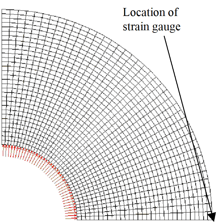
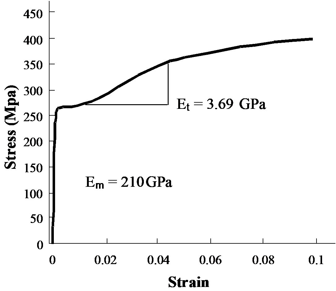
For an accurate analysis a very fine mesh was used. The surface node at the outer diameter in the finite element model, also shown in Figure 1, corresponds to the assumed location of a strain gauge. The material properties were translated from the experimentally determined stress - strain relationship, as shown in Figure 2. The model uses multilinear kinematic hardening with Bauschinger effect, a reduction in compressive yield stress, subsequent to tensile yielding. The model was simulated under a plain stress condition.
Preparation of the sample
EN1A free-cutting mild steel was used for experimental analysis because of its availability, and ease of autofrettage due to its very low yield strength. In order to increase ductility and increase strain hardening after yielding, the cold-rolled sample was annealed at 850ºC for one hour and then air cooled. The experiment consisted of the following equipment and instruments:
- Instron tensile testing machine.
- Strain Gauges type EA06060LZ120 from Measurement Group Vishay Inc.
- A 386DX laptop with analogue to digital data converter card.
A simple piston and cylinder arrangement as shown in Figure 3 was used to autofrettage prototype barrels.
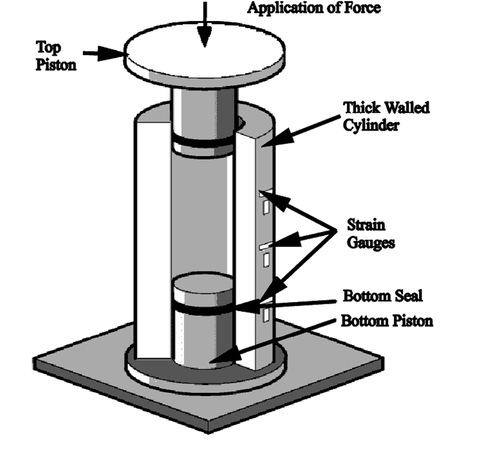
The sealing between the piston and cylinder was achieved by using James Walker’s special high-pressure elastomer O-rings. The force was applied to the piston head using an Instron tensile testing machine, to generate the required autofrettage pressure. This modelled autofrettaging as an open-end condition. Strain at the outer diameter was read through the gauges mounted on the outside surface of the cylinder.
Discussion of results
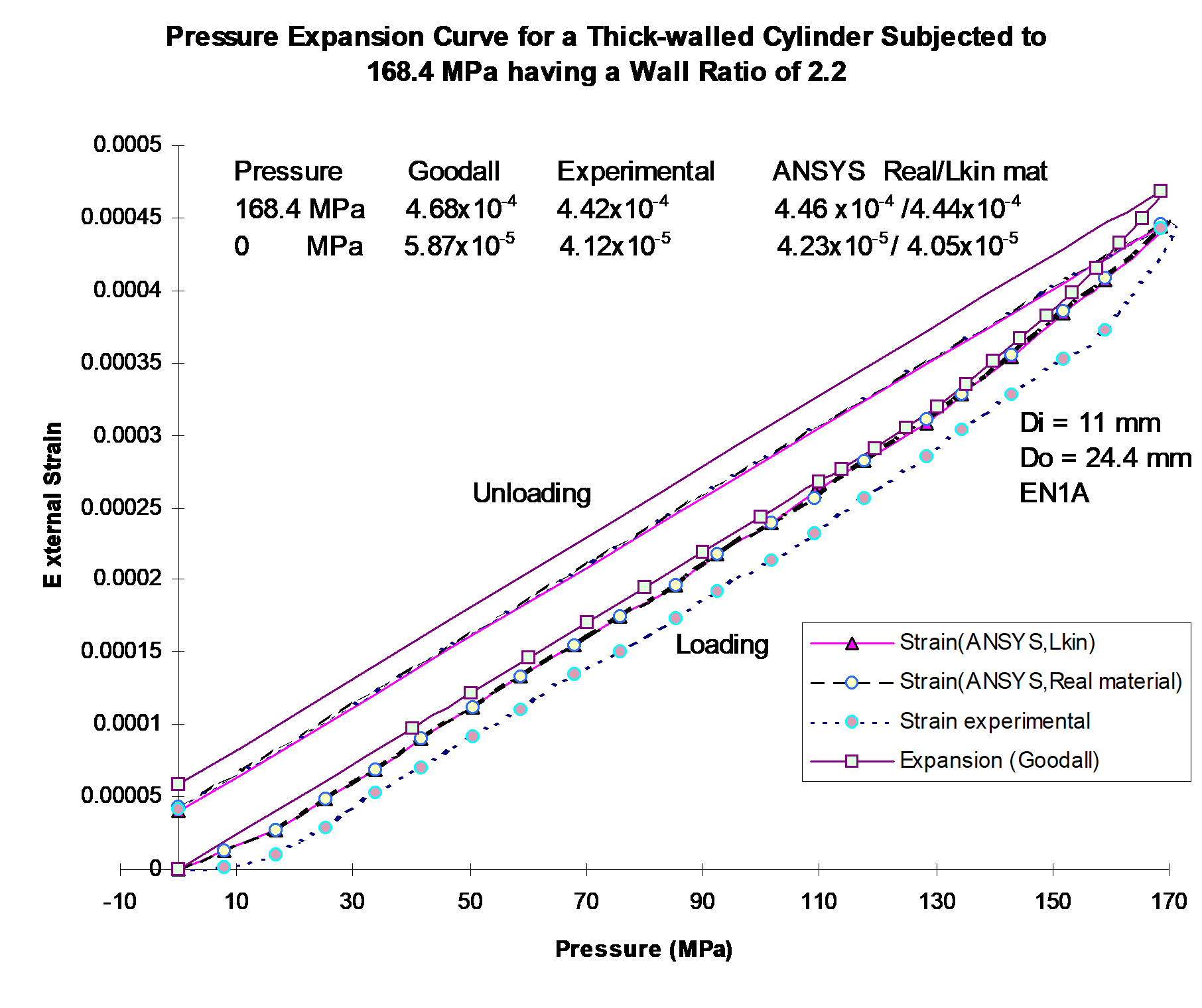
A comparison of experimental results (shown in Figures 4 and 5) with those of the analytical model shows that the experimental curve of EN1A does not exactly follow the analytical pattern. Whilst there is some divergence between the two, the trend is similar. In order to determine the cause, the data acquisition technique and overall system were checked thoroughly for any time lag, however, no abnormality was observed.
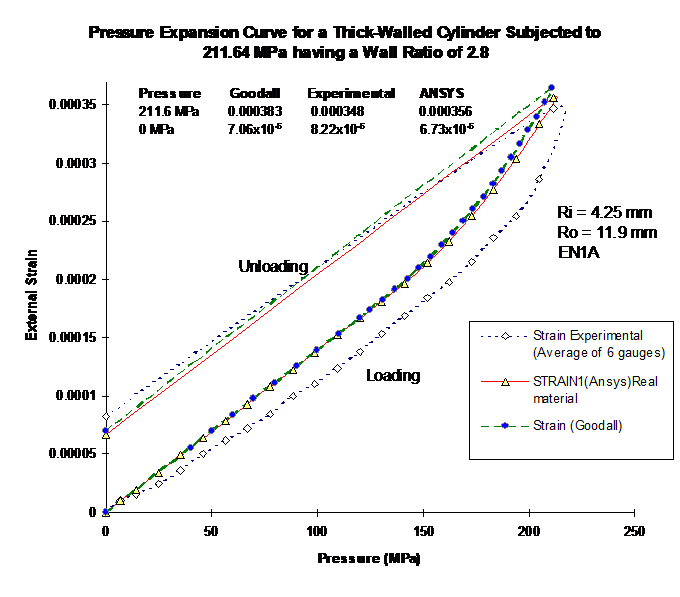
The difference between the experimental and analytical curves was greater in the case of the cylinder having the wall ratio of 2.8.
The experimental sequence was repeated to understand this behaviour. All tests showed approximately the same response, which indicated that it was related to the material property of EN1A. Nevertheless, the final magnitude of strain and percentage error, noted at the external diameter of the cylinder during the experiment, was in close agreement with that of Goodall and the numerical model as shown in Figures 4 and 5, and Tables 1 and 2.
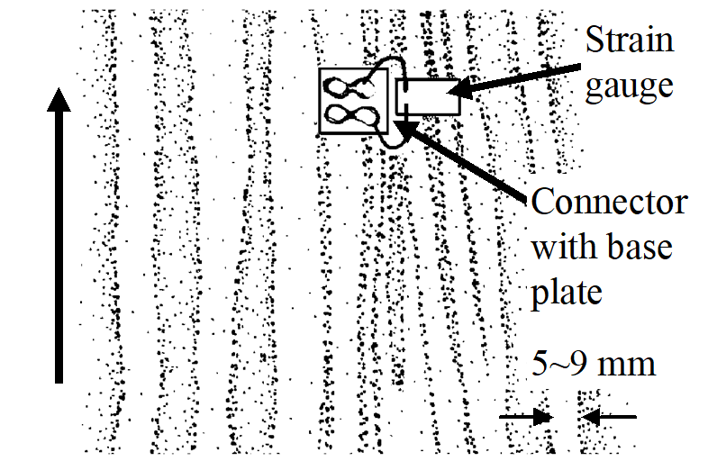
The probable reason of strain overshoot can be explained by discussing the stress-strain plot, which is for a typical low carbon steel (Figure 2), giving an upper and lower yield point with Luder's band. This term is described as "yield point phenomenon" by Diter [10] - details of which are given in [8]. A close macroscopic view of the cylinder surface also supported this fact. A band of stretch marks were visible as shown in Figure 6.
| Pressure MPa | % Error with respect to Goodall | % Error with respect to Experiment | ANSYS Linear kinematic | ANSYS Real material |
|---|---|---|---|---|
| 211.6 | - | 5.5 | 5.1 | 4.7 |
| 0 (Residual) | - | 29.0 | 31.0 | 27.0 |
| 211.6 | 5.8 | - | 0.45 | 0.9 |
| 0 (Residual) | 42.0 | - | 1.6 | 2.6 |
| Pressure MPa | % Error with respect to Goodall | % Error with respect to Experiment | ANSYS Real material |
|---|---|---|---|
| 211.6 | - | 9.1 | 7.1 |
| 0 (Residual) | - | 16.4 | 4.6 |
| 211.6 | 10.0 | - | 2.29 |
| 0 (Residual) | 14.1 | - | 18.1 |
The experiment was repeated, with certain modifications in the test arrangement, on a medium-carbon, low-alloy steel, but the phenomenon did not appear.
The comparison of a pressure/external expansion curve from Figures 4 and 5 reveals that the results from bilinear kinematic hardening are the closest to the experimental data and the error is approximately 0.5%. In the case of the ideal- elastic, perfectly plastic model [2], the error is 6%.
The FE model with multilinear kinematic characteristics has an error of 1~2.5%. This shows the similarity of the results from an FE model to conventional design methodology. Similarly, when the external residual strain upon release of pressure was compared with both the analytical and FE model, the latter was found to be nearer the experimental results. In the case of residual strain the error was less than 1.6~2.6%. Although the effect of strain hardening may be small (Figure 2: Et = 3.69 GPa), especially in this particular case, it does increase the accuracy of the model and hence the accurate prediction of residual stresses. This indicates the importance of material hardening in thick-walled cylinder design, when high performance is the main requirement.
Conclusion
A comparison of predicting external strains using finite element simulation with that of analytical and experimental models is made in this paper. A kinematic model including Bauschinger effect in FE simulation gives values that agree reasonably well with experimental values. This gives confidence in the use of FE analysis in the design of thick-walled cylinders, giving greater certainty in predicting the factor of safety and achieving high performance. Hence this numerical technique can be used with greater confidence as a tool for optimisation of thick-walled cylinder design.
Acknowledgement
The authors would like to express their gratitude to Mrs Ros Gibson for helping in typing and Miss Louise D Brown for providing a sketch of Figure 6.
References
[1] D. Roach and T. Priddy, “Continued Research on the Strain to Failure of Thick-Walled Cylinders Subjected to Internal Pressure”, ASME Pressure Vessel and Piping Conference, 1990.
[2] A. Goodall, "The Design of Gun Barrels - A Description of the Working Method" Part 1 The Monoblock Non-Autofrettage Barrels, Branch Memorandum P1/3/56 ARDE, 1956.
[3] A. Nadi, Plasticity, McGraw-Hill, New York.
[4] M. Steele, Journal of Applied Mechanics, Vol. 19, p. 133, 1952.
[5] D. Allen and D Sopwith, Proceedings of the Royal Society, Vol. A205, p. 69, 1951.
[6] C. MacGregor, L.F. Coffin and J.C. Fisher, F Franklin Institute, Vol. 243, p. 135, 1948.
[7]. R. Hill, The Mathematical Theory of Plasticity, Clarendon Press, Oxford.
[8] W. Prager and P. Hodge, Theory of Perfectly-Plastic Solids, Wiley, New York, 1951.
[9] ANSYS, FE Analysis Software, Swanson Analysis System Inc, PO Box 65, Johnson Rd, Houston, PA 15342-0065, USA. Tel : (412)746-3304, Fax : (412)746-9494.
[10] G. Dieter, Mechanical Metallurgy, SI Metric Edition, McGraw-Hill, New York.