
Volume 1, Number 2, July 1998
Main Battle Tank Stabilisation Ratio Enhancement Using Hull Rate Feedforward
Abstract
Improvements in the Stabilisation Ratio (SR) of current Main Battle Tanks (MBTs) are due to the use of hull disturbance feedforward. For the predicted im1provements to be realised, it is shown that the effects of non-linear friction must be compensated for. Simulations of a linear and non-linear Weapon Control System (WCS) are used to show the benefits of hull disturbance feedforward and the necessity to cancel out the effects of real friction in the non-linear case.
Introduction
The primary objective of the Weapon Control System (WCS) on a Main Battle Tank (MBT) is to maximise the probability of hitting a stationary or moving target with the first round, in the shortest possible time, from a stationary or moving vehicle. The current method of improving the isolation of the gun from the hull motion (stabilisation) is to use disturbance feedforward. The feedforward signal is derived from the angular rates of the turret and hull in pitch and yaw respectively.
Linear theory predicts substantial improvements in Stabilisation Ratio (SR) using disturbance feedforward. For an MBT the SR is defined:
for sinusoidal motion:
(1a)
and, for random motion:
(1b)
where; and are the angular rates of the hull and gun respectively. Thus the SR is a measure of the WCS's ability to reject the motions of the vehicle hull and it ideally should be infinite. In Equation (1a), the SR varies with frequency and for an MBT with disturbance feedforward it will usually be over 30dB at 1Hz. It is possible to determine the variation of SR with frequency from the random motions by using the Fourier transform, but in this paper, Equation (1b) will be used as a quantitative measure of the SR over all frequencies. The angular rates of the gun are normally measured at the breech or cradle using a rate gyro.
In practice, the effectiveness is reduced because of non-linearities - notably friction. Non-linear friction has a detrimental effect on the performance of a WCS from both a stationary and moving MBT. This paper investigates the effect of non-linear friction on the SR in elevation of an MBT moving over random terrain with an all-electric WCS. The effectiveness of one method of compensating for the non-linear friction is investigated.
Descriptions of the types of WCS used on current MBTs are given in [1,2,3,4]. These give the historical development of the systems used and a discussion of their advantages and disadvantages, with some information on their relative performances. The modelling and control of linear gun systems are given in [5,6,7]. These concentrate on developing or extending WCS models and investigating the different methods of controlling them. The problem with using a linear model of the gun system is that it can give misleading results because of the level of non-linear friction. Non-linear models of gun control systems have been developed in [5,7]. In these references, the effect of kinetic (Coulomb) and static (stiction) friction are shown to be significant.
This paper uses a simulation technique to examine the effects of non-linear friction on the SR in elevation with feedforward and friction compensation. The non-linear model and closed-loop controller used in this study have been taken from [5]. The principal non-linearity in this model is static and kinetic friction. This model allows MBT motions to be coupled into the model via the hull pitch rate and vertical acceleration of the trunnions. The gun barrel is modelled as two rigid sections and is referred to in the paper as a Lumped Parameter Flexible Beam Model (LPFBM).
Elevation model
A brief description of the elevation model is given here, the interested reader is referred to [5,7] for more detailed information. The description of the model is broken into two sections, linear and non-linear.
Linear elevation model
A diagram of the elevation channel is shown in Figure 1. The input to the elevation drive is a voltage to the servo-amplifier. The servo-amplifier produces a current, proportional to its input voltage. The prime mover is a dc servo-motor and in conjunction with the amplifier, can be considered as producing torque proportional to its input current [6]. The remainder of the drive-line consists of a gearbox, and rack and pinion. The servo-amplifier, motor and gearbox are represented by a single drive torque constant Kt. Sensors are used to measure the angular rate of the motor, and angular rate and position of the cradle.
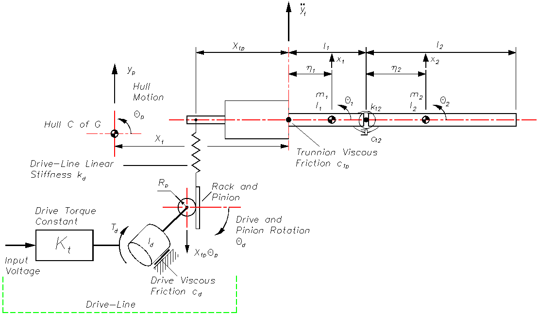
The drive inertia Id represents the motor inertia referred to the output of the gearbox. The drive torque is given by:
(2)
where vi is the input to the servo-amplifier. The viscous friction at the drive is cd. The radius of the pinion is Rp. The drive-line stiffness kd has been lumped between the rack and the cradle, which is equivalent to the model in [6,7]. The cradle, breech and gun barrel in this model are represented by two rigid sections, of length l1 and l2, mass m1 and m2, and moment of inertia about the centre of gravity I1 and I2. The distances to the centres of gravity are η1 and η2, the pin-joint linking the two sections has a torsional stiffness of k12 and viscous friction c12. This type of flexible beam model has been used to simulate and control flexible space-borne manipulators [8] and to investigate the design of WCSs [7]. The method used to select the lengths of the rigid sections is given in [5,7], in which the muzzle displacement and rotation for the first cantilever mode are matched to a finite element model. The torsional spring rate is calculated to make the first cantilever mode frequencies of the LPFBM and finite element models equal.
The inputs to the model are the voltage to the servo-amplifier vi, the trunnion vertical acceleration and the MBT hull pitch rate . The outputs from the model are the drive angular velocity , the breech angle and velocity and the muzzle angle . The equations of motion for small motions are:
(3)
where the mass M1, damping C1, stiffness K1, and input I1 matrices are given by;
(4)
The vector of inputs and outputs are:
(5)
In state space form the equations for the model are given by:
(6)
where:
(7)
and I is a unit matrix of appropriate dimensions.
Non-linear elevation model
The non-linear elevation model has been formed by incorporating non-linear friction into the drive and trunnions, and the out-of-balance of the gun. The out-of-balance torque was caused by the centre of gravity of the elevating mass being 8.0mm in front of the trunnions. The non-linear friction model used is a modified reset-integrator representation [9]. The modification to this model includes a random component of friction added into its output. This is generated by integrating white noise and adding it into the friction force, the mean level being zero and the standard deviation being approximately 1% of the kinetic friction. The static friction provides an additional 25% of the kinetic friction level. The drive friction was taken as 1% of the trunnion friction. For the elevation system under investigation the trunnion kinetic friction has been set to 1kNm. A full set of data for the linear and non-linear models and their derivation can be found in [5].
Closed-loop controller
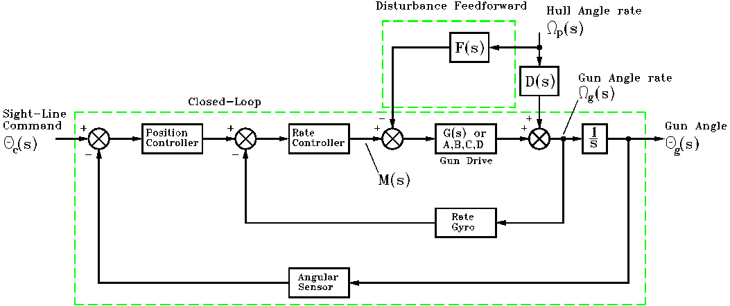
To investigate the performance of the elevation model, a classical closed-loop controller was designed, which was based on the open-loop frequency responses. The form of the closed-loop controller is shown in the lower part of Figure 2, and consists of an inner-loop breech rate controller and outer-loop breech position controller. The outer-loop controller is based on a traditional proportional plus integral structure, while the inner-loop has a proportional controller augmented with a notch and low pass filter. No attempt has been made to optimise the response of the closed-loop WCS.
Feedforward controller design
If a disturbance acting on a control system can be measured, then this signal can be used to help reduce the effect of that disturbance on the output of the control system. A diagram showing how disturbance feedforward is implemented is shown in the upper part of Figure 2, where s is the Laplace variable. In this diagram the disturbance signal is Ωp(s), the command input is M(s) and the output is Y(s). The transfer function blocks G(s), F(s) and D(s), represent the system to be controlled, the feedforward controller and disturbance (coupling the hull motion into the gun).
It can be shown [10] that for the disturbance to have no effect on the gun Ωg(s), that the ideal feedforward controller Fi(s) is;
(8)
Thus if the feedforward controller is the ratio of the disturbance and system transfer functions, then the effect of the disturbance will be cancelled out.
To demonstrate the effectiveness of disturbance feedforward, the model shown in Figure 1 has been reduced to a single degree of freedom. This has been accomplished by removing the flexibility in the barrel and drive-line. The transfer function for this system is then given by;
(9)
where:
and
The ideal feedforward transfer function is given by:
(10)
In this case, the ideal feedforward controller is an improper transfer function (the order of the numerator is greater than the denominator). To implement this transfer function it must have the effect of the differentiator removed from it at high frequency. It must be made proper. This can be achieved by incorporating a low pass filter into the feedforward controller, allowing it to be implemented. For this work a single order low pass filter with a cut-off frequency of 15Hz has been used. It has been assumed that the angular rate of the hull is measured by a rate gyro with the same dynamic characteristics as the one for the inner-loop rate control [5].
This feedforward controller has been designed using a linear model of the elevation channel. One of the most significant non-linearities in the system is the static and kinetic friction present in the trunnions and drive-line. An effective method of compensating for this non-linear friction is to add an offset onto the feedforward signal, which is dependent on the relative motion between the gun and the hull. This signal is an attempt to cancel out the effects of the friction. A window on the relative velocity between the gun and hull is used to inhibit the offset below a pre-set difference.
This form of non-linear friction compensator is relatively simple and many other more complex possibilities exist [11]. For a given size of window the important parameter to select is the amplitude of the offset signal Vfc. This is going to be of the order of the level of kinetic friction. For a window size of Ωwrads-1 the response of the friction compensator is give by;
(11)
In this paper Ωw= 10mrads-1.
Simulation results
A diagram of the elevation axis control system with hull angular rate feedforward is shown in Figure 2. In this investigation simulation results have been obtained for the following conditions:
- linear model, with and without hull pitch rate feedforward;
- non-linear model, with and without hull pitch rate feedforward and friction compensation; and
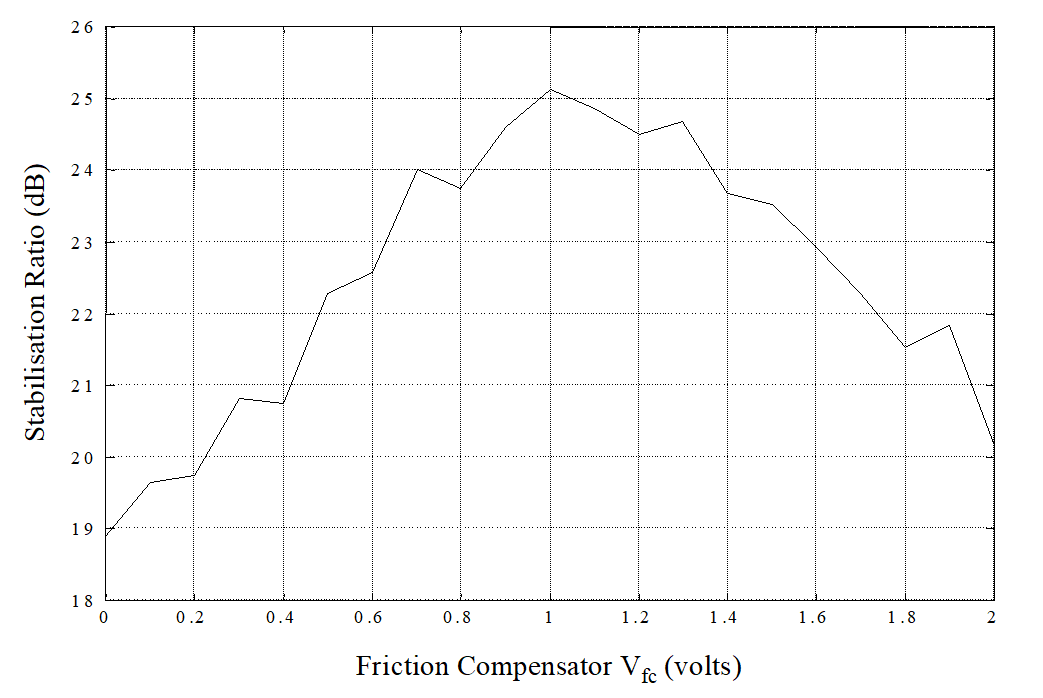
- non-linear model with feedforward and friction compensation with the amplitude of Vfc varying from 0V to 2.0V.
The MBT vehicle model and terrain data have been taken from [5].
Linear model
The dramatic improvement in isolating the gun from the hull motion with hull pitch rate disturbance feedforward is shown in Figure 3. Without feedforward, the SR is 21.2dB and with feedforward 27.0dB. This is an improvement of 27.4%. Thus from this linear model it is shown that hull pitch rate feedforward gives a significant improvement in the SR.
![Linear model breech angle response; with feedforward [solid], no feedforward [dash].](/journals/journal-of-battlefield-technology/volume-01/issue-02/assets/1-2-2-purdy/figures/figure03.png)
Non-linear model
For the non-linear model without disturbance feedforward the SR is significantly less than with the linear model shown in Figure 3. The SR for the non-linear model in this case is 15.4dB, which is a reduction in performance of 27.4%, compared with the linear model without feedforward.
Applying hull pitch rate feedforward to the non-linear model, Figure 4 shows an improvement in SR from 15.4dB to 18.9dB or 22.7%. Thus the non-linear system with disturbance feedforward is 10.8% worse than the linear without feedforward.
![Non-linear model breech angle response; with feedforward [solid], no feedforward [dash].](/journals/journal-of-battlefield-technology/volume-01/issue-02/assets/1-2-2-purdy/figures/figure04.png)
Using the non-linear model with feedforward and friction compensation and varying the amplitude of the offset Vfcfrom 0V to 2.0V gives the SR shown in Figure 5. This figure shows clearly an optimum value of Vfc of 1.0V. This equates to a drive torque of 54.4Nm, which is the approximate value to cancel the kinetic friction at the trunnions. With the friction compensator set to 1.0V, the effect on the motion of the gun is shown in Figure 6. The SR with this friction compensator is 25.1dB, which is an increase of 63.0% over the system without. With the friction compensator the SR is 8.5% less than the linear system with feedforward.
![Non-linear model with feedforward breech angle response; with friction compensation [solid] and without friction compensation [dash].](/journals/journal-of-battlefield-technology/volume-01/issue-02/assets/1-2-2-purdy/figures/figure06.png)
Conclusion
The results of breech rotation and SR from a simulation of a linear and non-linear elevation WCS of an MBT crossing a piece of random terrain have been presented.
The improvement in SR for the linear WCS model using hull rate feedforward compared to that without was over 27%. The non-linear WCS with feedforward showed an improvement of almost 23% but its SR was less than the linear without feedforward.
A simple method of attempting to compensate for the non-linear friction was shown, when correctly set-up, to improve the SR of the non-linear WCS by 63% (being only 8.5% worse than the linear with feedforward).
References
[1] S. Feinstein, “The Evolution of the Tank Fire Control System”, Armor, pp. 21-24, Jan-Feb 1973.
[2] R. Ogorkiewicz, “Stabilised Tank Gun Controls”, International Defence Review, pp. 725-728, May 1978.
[3] W. Kölbl, “Fire Control Systems for Main Battle Tanks”, Military Technology, Vol. 5, No. 21, pp. 63-68, Feb 1981.
[4] C. Delamain, “Fire Control Systems for the Main Battle Tank”, Tank Journal, pp. 13-16, Feb 1991.
[5] D. Purdy, “Modelling and Simulation of a Weapon Control System for a Main Battle Tank”, Proceedings OfThe Eighth US Army Symposium On Gun Dynamics, 14-16 May 1996.
[6] D. Dholiwar, “Development of a Hybrid Distributed-Lumped Parameter Open Loop Model of Elevation Axis for a Gun System”, Proceedings OfThe Seventh US Army Symposium On Gun Dynamics, 11-13 May 1993.
[7] D. Purdy, “An Investigation Into the Modelling and Control of Flexible Bodies”, PhD. Thesis, Cranfield University (RMCS), England, 1994.
[8] P. Woerkom, “On Fictitious Joints Modelling of Manipulator Link Flexibility for the HERA Simulation Facility Pilot”, National Aerospace Laboratory NLR The Netherlands, Report No. NLR TR 88086 U, 1988.
[9] D. Haessig and B. Friedland, “On the Modelling and Simulation of Friction”, Transactions OfThe ASME Journal Of Dynamic Systems, Measurement And Control, Vol. 113, pp. 354-362, Sep 1991.
[10] J. Maciejowski, Multivariable Feedback Design, Addison Wesley, pp. 10-13, 1989.
[11] B. Armstrong, Control Of Machines With Friction, Kluwer Academic, 1991.