
Volume 1, Number 2, July 1998
Analysis of the Forces Acting on a Shoulder Supported Weapon During Firing
Abstract
An analysis of the forces acting on the SA80 assault rifle during firing was undertaken to investigate barrel rotation whilst the bullet was travelling in the barrel. Bullet displacement and velocity from initial movement to the point when the bullet left the barrel were first calculated. Two separate numerical methods were used to calculate barrel angular displacement and angular velocity against time caused by the propellant pressure acting on the breech face and the angular acceleration of the bullet. The two different methods gave good agreement, giving a barrel angular displacement of 0.066rad and an angular velocity of 3.75 x 10⁻⁴ rad/s respectively.
Introduction
When a shoulder-supported weapon is fired, there are a number of forces acting on it, which tend to cause the weapon to move during the firing process and whilst the projectile is travelling down the barrel. Thus, when the projectile exits the barrel, it will be pointing in a different direction to when the weapon was initially aimed. If this movement is consistent, the weapon can be zeroed to compensate for these movements. With high levels of training it is possible for any inconsistencies to be reduced to an acceptable level. Unfortunately, in an operational environment, when high levels of stress are experienced by the firer, consistency deteriorates. Thus it is desirable to reduce weapon movement during firing to a minimum so that firer inconsistencies have minimum effect.
When being fired from the prone position, there is a tendency for the weapon to rotate about the point of support, which is the shoulder of the firer. The purpose of this paper is to analyse the movement of the weapon during firing if it is allowed to rotate about the butt. The weapon used in this analysis was the 5.56mm calibre SA80 Individual Weapon fitted with the SUSAT optical sight as used by the British Army.
Propellant pressure
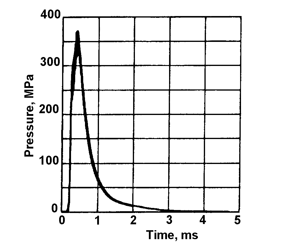
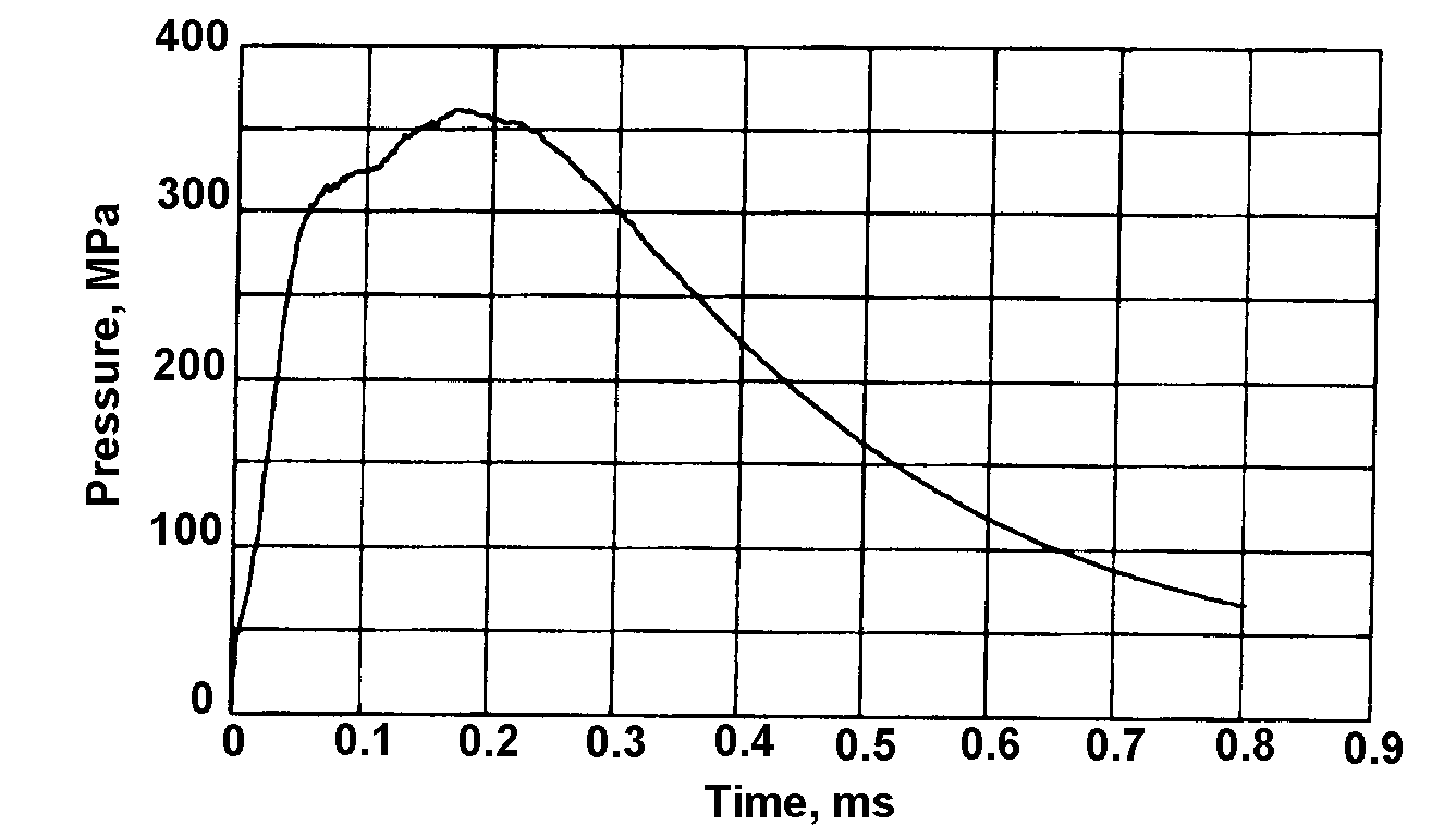
The main force acting on the weapon results from the pressure in the chamber and barrel as the propellant burns and accelerates the projectile down the barrel. This pressure was measured using a piezoelectric transducer positioned immediately in front of the cartridge chamber and 51.5mm from the breech face. A digital recording oscilloscope was used to record the pressure. Ten pressure readings were taken and the numerical average taken for the subsequent analysis of weapon movement. The pressure was measured at intervals of 2µs over a period of 10ms giving a total of 500 pressure readings. Figure 1 shows the average measured pressure/time curve for the standard Radway Green L2A2 5.56mm calibre round measured over ten separate firings.
In addition to a knowledge of the pressure at the chamber, it is necessary to know the pressure at the base of the projectile as it passes down the barrel to enable the projectile velocity, and hence projectile position, to be calculated for different positions in the barrel. The following expression [1] was used for calculating the pressure on the base of projectile at different distances(s) from the breech:
(1)
where:
px(t) = pressure at distance x from the breech;
ps(t) = pressure on base of projectile at a distance s from the breech;
C = propellant mass (1.69g for L2A2 5.56mm ball round);
A = bore cross sectional area (25.5mm2 for 5.56mm barrel);
s = distance from base of the projectile the breech;
vp = velocity of projectile; and
t = time.
Thus, pressure on base of projectile when x = 0 is:
(2)
If the pressure at px1(t) is known then the pressure ps(t) can be found. From this, the projectile velocity vp and the distance travelled, s, in the barrel can be found.
The solution for the different differential equations cannot be achieved analytically, so the Runge-Kutta method improved with Fehlenberg coefficients was used. This algorithm was already implemented in MATLAB [2] and the ode45 algorithm was used. However, it was necessary to obtain a numerical expression for pressure px1(t). Again using MATLAB, a seventh order polynomial was found which approximated well to the function px1(t).
The projectile was spin stabilised. The twist rate for the rifling was one turn in 178mm. If the initial engraving forces are ignored, the forces acting on the projectile are the angular acceleration force and the friction force as shown in Figure 2.
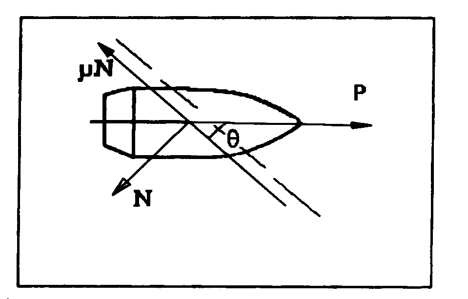
Consideration of the forces acting on projectile gives the following equations of motion for the projectile:
(3)
where:
mp = the mass of the projectile;
µ = coefficient of friction between barrel and projectile;
N = the normal force on active side of rifling;
ω = angular velocity;
d = diameter of the bore of the barrel; and
Jp = moment of inertia of bullet about axis of symmetry.
After rearrangement, and using , the following equation of translation motion for the projectile is obtained:
(4)
where θ is the angle of twist of the rifling.
Using Equation (1):
(5)
The function px1(t) can be expressed as the following seventh order polynomial:
(6)
It is necessary to solve (numerically) the following differential equations to find the projectile velocity at different distances travelled by the projectile from the breech face:
(7)
Figures 3 and 4 plot the above equations and show the displacement of the projectile and projectile velocity as a function of time.
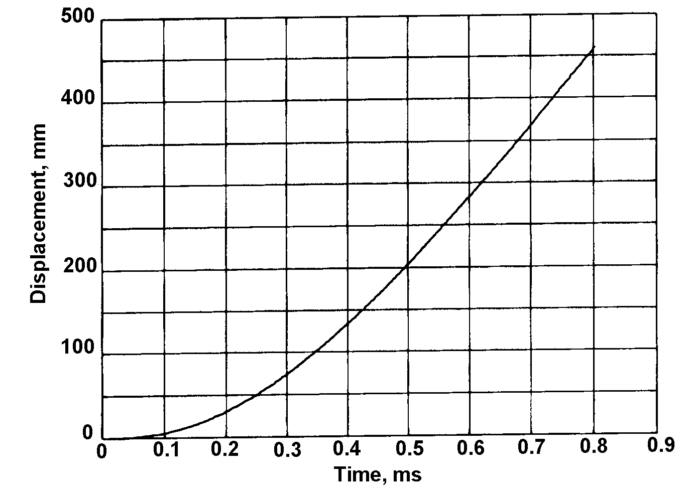
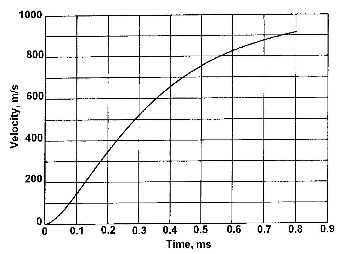
The distance from the base of the projectile before firing to the muzzle of the barrel was 460mm. From Figure 2 it can be seen that the length of time that the projectile was in the barrel during firing was therefore 0.8ms. Using the values of projectile velocity and distance moved by the projectile, Equations (7) gives the pressure acting on breech against time, which is shown in Figure 5.
The values used for the ammunition and the weapon when solving the differential equations were as follows:
C = 1.69g;
mp = 4.09g;
d = 5.56mm;
Jp = 1.55 x 10⁻⁸kgm2;
θ = 5.6º; and
µ = 0.1.
Movement of the weapon during firing
Figure 6 shows the forces acting on the rifle during firing. The weapon is assumed to pivot freely about the mid point of the butt pad at point ‘O’ and has no restraints on its movement.
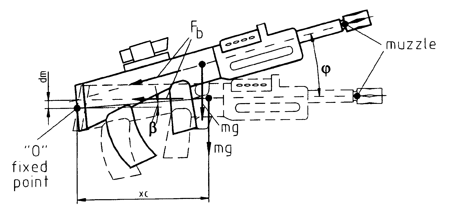
The equation of motion of the rifle about the fixed point “O” during the time the bullet travels along the barrel is given by [3]:
(8)
where:
o = sum of moments of all external forces about “O”;
Jo = moment of inertia of the rifle about point “O”; and
= angular displacement of the barrel.
Developing the left term, the sum of moment of the external forces, the following is obtained:
(9)
where:
Fb = force acting on the breech of the weapon,
dm = vertical off set between pivot point and centre of gravity,
r = radius of rotation of centre of gravity,
β = angular displacement of centre of gravity before firing.
To solve Equation (9) the following two different methods were used.
Assuming angle is small
If angle is a small the following approximation can be used:
(10)
Thus rotational movement of the rifle about the fixed point “O” is given by:
(11)
where:
xc=rcosβ is the x co-ordinate of centre of gravity about the fixed point "O"; and
Fb(t) = force on breech as a function of time.
The numerical value of Fb(t) is known for steps of 2µs. Using a polynomial interpolation, an analytical expression for this function can be obtained using a 5th order polynomial:
(12)
The solution of Equations (7) can be determined by integrating twice from 0 to tm and making angular velocity and angular displacement zero when time is zero.
(13)
(14)
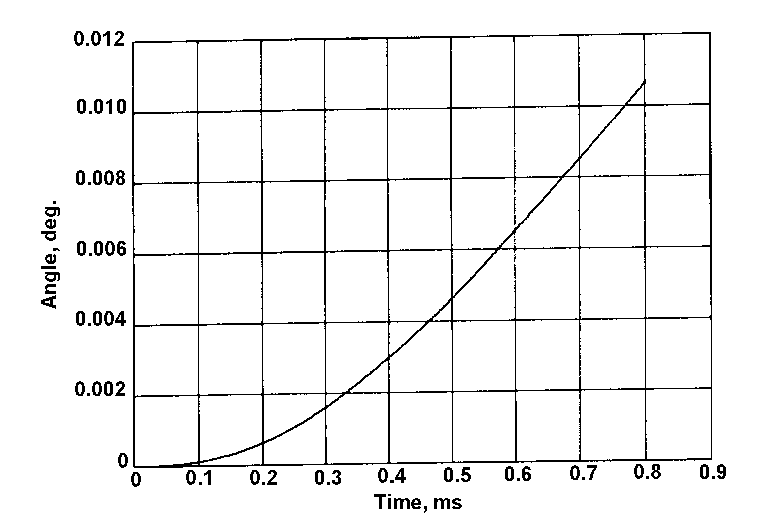
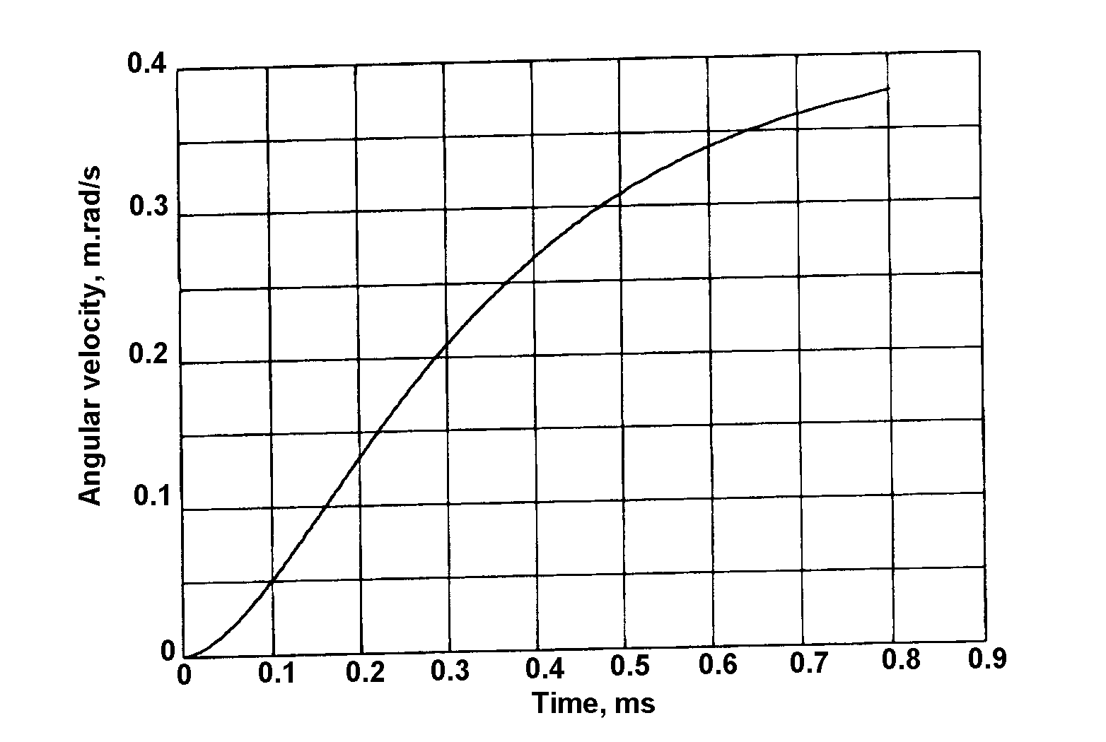
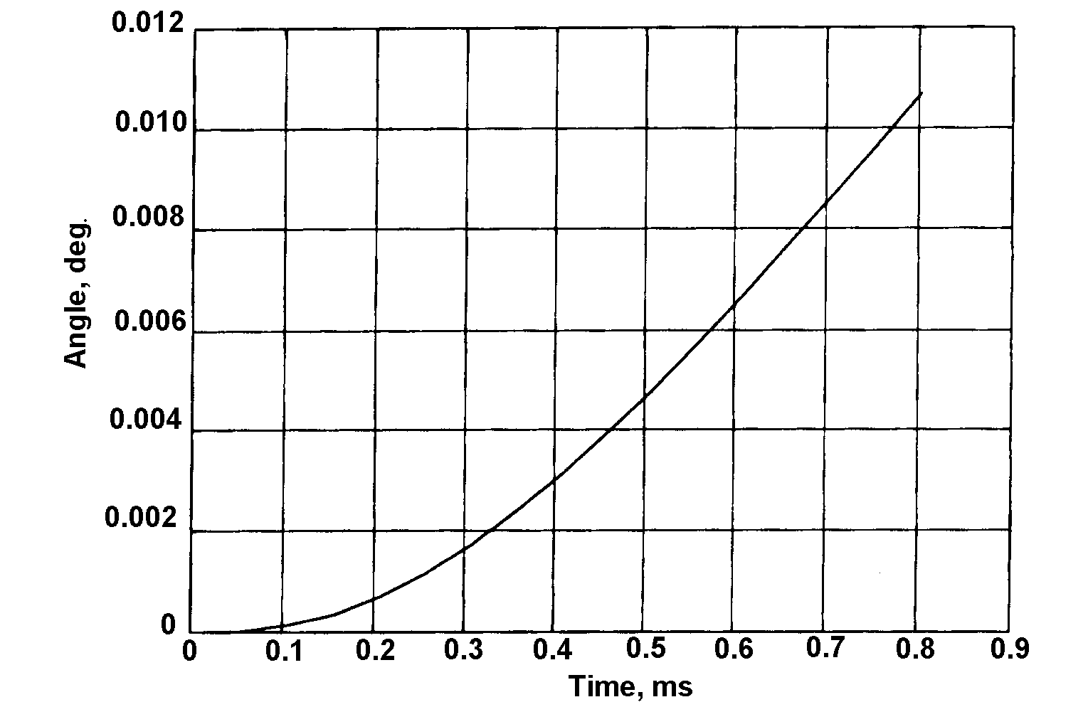
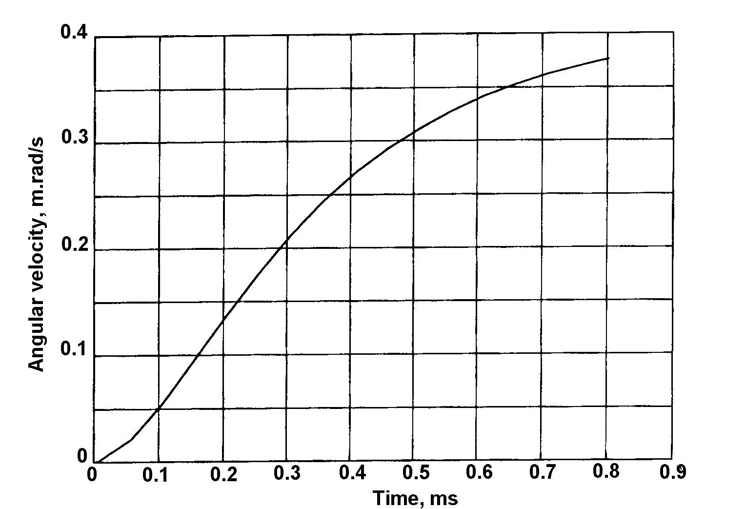
Figure 7 shows the calculated angular movement and Figure 8 shows the angular velocity of the barrel whilst the bullet is passing down the barrel.
Polynomial interpolation using Runge-Kutta method
The same 5th order polynomial given in Equation (12) is used. Equation (9) can be rewritten as:
(15)
Also, xc=rcosβ and yc=rsinβ (and noting ) so that:
(16)
Equations (16) were solved using the Runge-Kutta method and Fehlenberg coefficients were used and integrating steps varied. A MATLAB routine was used for step optimisation. Figures 9 and 10 show the calculated results.
Discussion
There is good agreement between the two methods for calculating angle of rotation of the barrel and barrel angular velocity. These gave values of angular displacement of 0.066rad and an angular velocity of 3.75 x 10⁻⁴ rads-1 when the bullet exited the barrel. This would have resulted in a movement in the point of impact of the bullet at 100m of 26mm due to the position of the barrel and 0.04mm due to its angular velocity. There are several variables that could affect actual values of barrel movement not considered in the calculations. Weapon centre of gravity varies with the quantity of ammunition in the magazine. This effect can be significant because of the relatively large distance of the centre of mass of the ammunition from the centre of mass of the weapon.
The pivot point of the butt was taken to be at its centre. In practice, there will be no single pivot point but an area over which the force is applied to the shoulder of the firer. An additional turning moment (not taken into account in the analysis, because the worst case only was being considered) is that applied by the forward hand of the firer on the fore-end of the weapon. The point at which the weapon is held is ahead of its centre of gravity so that the turning moment will be applied in the opposite direction to that of the firing turning moment. This will vary with different firers.
Conclusions
This analysis has shown that the design approach used for modern assault rifles of ensuring that the barrel centre line, weapon centre of gravity and butt pivot point are closely in line is very effective in reducing weapon movement during firing. This same approach could be further developed to investigate the effectiveness of muzzle compensators, acting whilst the bullet is travelling down the barrel, to reduce weapon movement during firing.
References
[1] Textbook of Ballistics and Gunnery, HMSO 1984.
[2] MATLAB/SIMULINK Reference Manual, The Math Works Inc, 24 Primer Park Way, Natlick, Mass.
[3] D. Allsop, et al, Military Small Arms, Design and Operating Methods, Brassey’s (UK) Ltd, 1997.