
Volume 1, Number 1, March 1998
Battlefield Surveillance Radar
Abstract
This review article outlines the operational requirement for Battlefield Surveillance Radar, and the design challenges that result. It is shown that the clutter problem on the battlefield leads to a Pulse Doppler solution. Design requirements are outlined and a typical current design is addressed. Possible future developments are discussed, and it is argued that future developments will be driven by the need for covert operation, with a drive towards active phased array antennas and LPI waveforms. In both cases, this takes advantage of expected advances in technology, and will lead to a more effective equipment.
Requirement
Ground-based Battlefield Surveillance Radar is intended to provide coverage of the local area, detecting all targets of interest out to the local horizon. The distance to this horizon depends on the terrain, but is typically 6 km in North West Europe. In other part of the world, however, the terrain is flatter, giving longer horizon distances. These considerations lead to a typical range requirement of anything from 6-25 km for radars of this type.
Typical targets would be:
tanks and other moving vehicles,
personnel,
spoil from fall of shot from own mortar and artillery firings, and
helicopters.
The main difficulty faced by the radar is the competing radar echo provided by the stationary clutter background. This tends to be very much larger than the echoes from wanted targets, and results in the need to use Doppler discrimination. This allows good clutter rejection, and also gives some capability for target classification on the basis of radial velocity measurement. Since there is also a requirement to measure target range, the obvious radar design is pulse Doppler.
Internal coherence and clutter reference as doppler radar designs
All Doppler measuring radars operate by comparing the frequency of the target echo with that produced by the transmitter. The idea is illustrated in Figure 1.
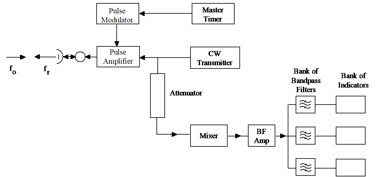
Any movement by the target towards or away from the radar results in a frequency change in its echo, caused by the Doppler effect. In the radar receiver, this target echo is compared directly with a reference waveform from the transmitter, and any difference in frequency is extracted. The value of this difference is then measured in a bank of filters. Echoes from stationary clutter are not Doppler shifted and consequently do not produce a frequency difference to be measured and detected by the filter bank. Hence moving targets are detected by virtue of their motion, while the competing clutter echo is suppressed. This type of radar detection is known as internally coherent detection.
However, it should be noted that the target echo is subject to the time delay caused by the echo time. Therefore it is very important that the transmitter frequency does not change between transmission and reception. If this does happen, then the Doppler measurement would contain an error that would cause stationary targets to appear to have non-zero Doppler. This places a severe stability requirement on the transmitter. Nowadays, this requirement is easy to meet, and so all modern systems are internally coherent, since this is by far the best method. However, in the past, transmitter stability was not normally good enough, and this led to the use of clutter reference as a method of extracting the Doppler from moving targets. Since equipments using this method still exist around the world, it is necessary to mention the technique, and Figure 2 illustrates the idea.
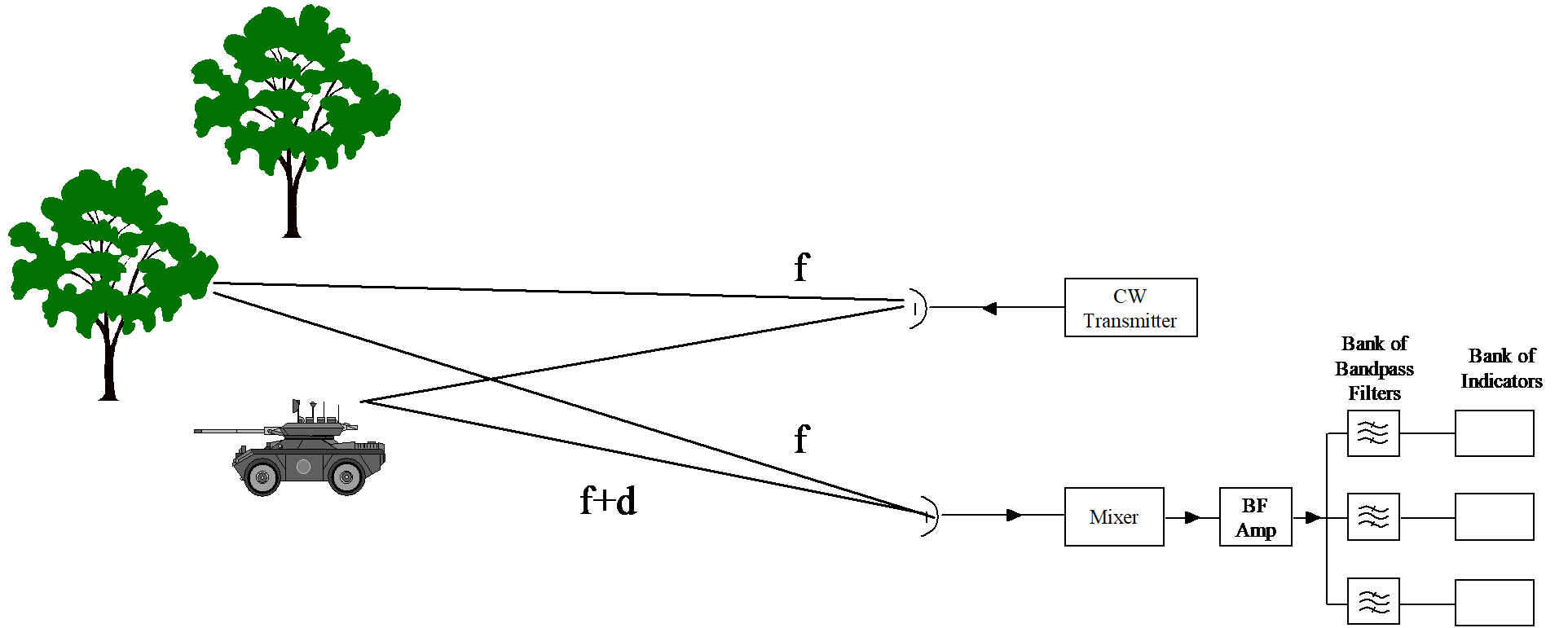
Clutter reference radars do not feed the transmitter waveform directly into the receiver. Instead, they rely on echoes from stationary clutter to provide a zero-Doppler shifted signal into the receiver, which can then be compared with any target echo. The presence of a Doppler shift will cause beating at the difference frequency between the two received signals, and hence the Doppler frequency can be extracted. Since the clutter echo has also suffered a time delay, its frequency will be that of the transmitter at the time of transmission, and consequently the need for transmitter stability can be greatly relaxed. However, this method does rely on the presence of the stationary clutter, otherwise the necessary clutter echo would not be present. It also relies on the echo strengths of clutter and target being fairly similar. This is because the amplitude of the beat frequency is a function of their relative strengths, and is largest when the two echoes are of the same amplitude. When the two are significantly different, the resulting beat frequency is small in amplitude, and this reduces its detectability. This amounts to a statement that target echoes are still easily overwhelmed by the clutter background. Internally coherent systems do not suffer from this limitation, and are consequently to be preferred now that transmitter stability is not the issue that it once was.
Sub-clutter Visibility
Since Doppler measuring radars can remove stationary clutter while retaining targets, it follows that the target echo can start off much weaker than the clutter echo. Only when the clutter echo is removed by suitable filtering does the target become detectable. This ability to detect targets that are well below the strength of the competing clutter is known as the sub-clutter visibility capability of the radar.
For an internally coherent radar, the sub-clutter visibility can be as high 30 dB, that is targets can be 1000 times weaker than the clutter, and still be detected satisfactorily. The actual value depends on how much the ratio of target echo to clutter background can be improved. This is limited by the performance of the filter bank, the linearity of the detection process, and the antenna scan rate. Practical values may be found in the region of 40-50 dB (an improvement of 10,000 to 100,000). This means that a target echo that is initially 30 dB below the clutter background can be brought 10-20 dB above the clutter background by this process. This is generally sufficient for satisfactory detection.
Velocity resolution
Target detection also depends on the radial velocity of the target; target velocities that are very small (that is, almost stationary) can be quite difficult to separate from the (actually stationary) clutter echo, as their Doppler frequencies differ by so little. The ability of the radar to separate very similar radial velocities is known as the velocity resolution of the radar. In practice this depends on the scan rate of the radar, coupled with its antenna beamwidth. This is because these two parameters control the length of time (the dwell time) that the radar illuminates the target on each scan. The longer the dwell time, the more precise the measurement of Doppler frequency becomes, and since Doppler shift and radial velocity are linked by:
fd = 2Vr / λ
where λ is the wavelength of transmission, it follows that longer dwell times also give more precise measures of radial velocity. This means that closer values can be separated, allowing smaller target velocities to be separated from the stationary background. For good velocity resolution, therefore, slow scan rates and wide antenna beamwidths (and, incidentally, short transmission wavelengths) are desirable. (However, a large antenna beamwidth is undesirable in terms of the angular resolution of the radar, and so scan rate is the principle way of controlling velocity resolution in practice.)
Battlefield surveillance radar design
The BSR requirement is to detect men and tanks out to only relatively short distances (the local horizon) in all weathers with man-portable equipment. The detailed design of such a radar is of necessity a complicated process involving many iterations. The intention here is to outline typical values for the radar’s parameters, and then to show that these values will give a design that meets the requirement.
Antenna Size and Transmission Frequency. Antenna size is important in radar design because the detection range of the system is affected significantly by it. Ideally, the bigger the antenna the better, but in a BSR the size is limited by the requirement for portability. In practice, an antenna 50-60 cm in diameter might be a reasonable maximum. If this antenna is to give an acceptably narrow beamwidth, then the selection of a high transmission frequency is desirable. However, the radar is required perform in all weathers, and so attenuation of the radar signal caused by rain, etc, must be considered. This rises with frequency, necessitating a compromise to be made between these two conflicting requirements. In practice, the short detection range allows the transmitter frequency to be selected in the 10-20 GHz range. This frequency range keeps the attenuation within bounds while still allowing the small antenna to produce an acceptable beamwidth. The beamwidth of a circular antenna is approximately:
70λ/D
where D is the antenna diameter. At 15 GHz, for instance, this would give a beamwidth of around 2.5°. This value is much the same as that found in a fighter aircraft, and much better than that typically found in a radar-guided missile.
Power. As stated earlier, the required detection range for this type of radar is in the region of 6-25 km, depending where in the world it is deployed. These are very short ranges for radar sensors, and can be achieved with very low transmitter powers (mean values in the order of a few Watts). This power level makes the production of small equipment far easier. In particular, it allows the use of a battery as the power supply, making the radar quiet in the acoustic sense.
PRF. The pulse repetition frequency (PRF) is determined from the requirements for unambiguous range and velocity measurement. For unambiguous range measurements and the avoidance of eclipsing, the PRF must be no higher than:
c/2Rmu
and since Rmu must be at least as large as the required maximum detection range, it follows that the PRF must be no higher than:
c/2Rmax
For a maximum detection range of 25 km, this means a PRF of no more than 6 kHz. Similar arguments apply to velocity measurement. Here the key thing is to avoid blind speeds, which occur at frequency intervals equal to the PRF. At 15 GHz, the Doppler shift from a moving target is 100 Hz/m/s. Hence if velocities on the battlefield are limited to 30 ms-1, say, then blind speeds will be avoided provide the PRF is higher the 3 kHz. Thus, for this application of Pulse Doppler, a single value of PRF can satisfy both range and Doppler requirements. Typical figures are around 5,000 pps.
Pulse Width. The transmitted pulse width is determined from the minimum range requirements. Since the receiver must be switched off when the transmitter is on, each microsecond of pulse width produces 150 m of blind zone close to the radar. Typical practical values are in the region of a microsecond or less, allowing the radar to detect anything further away than 150 m or so.
(Range resolution also depends on pulse width, but in this case, pulse compression can be employed to produce good performance in this parameter.)
Radar Detection Range. The radar range equation can be used with the above parameters to establish that the radar will meet the requirement. Against tank targets (10m2), and with the low-noise receivers available to today, the single-hit detection range of the radar is in the range 13-14 km. Using a realistic amount of integration, this can be raised to 33-35 km relatively easily. Taking account of attenuation through the atmosphere reduces this value to about 25 km in good conditions. Poor weather reduces the detection range further, to a value of around 21-22 km for rain falling at a rate of 5 mm/hr. This range can be increased to the required 25 km during the design stage by raising the mean output power from the 2 W used here to 4-5 W. Alternatively, a longer range can be obtained by slowing the scan rate to increase the integration. As this is easy to vary in the field, this technique can be reserved for poor weather conditions, returning a higher scan rate in good conditions. Either way, the requirement can be met.
Processing. The main receiver processing required is obviously the use of a Doppler filter bank. Nowadays this is usually produced by computation, using an algorithm known as a fast Fourier transform (FFT). The FFT allows rapid computation of the outputs that would obtained from a “real” filter bank. Nowadays the processor required is cheaper and less bulky than a filter bank consisting of hardware components. This allows a reduction in the weight and cost of the radar.
In addition to the filter bank, the radar can also use one or two other processing techniques, intended to cope with the fact that clutter echoes tend to vary from place to place. Variable detection thresholding allows that radar to make automatic adjustment of its detection threshold from moment to moment in response to local clutter conditions. This is intended to optimise target detection all clutter conditions. This technique is commonly known as Constant False Alarm Rate (CFAR) processing.
Future developments
The conventional design of BSR suffers from several problems:
- The radar transmits close to the enemy, and is therefore vulnerable to detection by enemy ESM systems.
- The mechanically scanned antenna does not fully allow for the radar to change its dwell time from moment to moment. Such a facility would enable the radar to enhance its detection performance whenever necessary. (This might be to detect smaller targets, or more slowly moving ones.) It also requires the radar to examine areas that may not be a great interest.
The risk of detection by enemy ESM systems encourages the use of Low Probability of Intercept (LPI) waveforms, in addition to the low output power already used. Phase-coding and frequency agility are techniques that could be profitably employed, and one would expect to see these in any future design of BSR.
The relative inflexibility of the mechanically scanned antenna can be removed by the use of an active phased array. Such an antenna would allow total flexibility over the scanning of the radar beam. This would allow longer dwells in areas of interest, with proportionally less time spent in regions of low interest. The radar would then become much more of a multifunction device, which could be optimised a dynamic basis for different roles within the battlefield (fall of shot, detection of helicopters, etc). Complete flexibility of scan would also allow the randomisation of the search pattern, making analysis by hostile ESM systems more difficult, should they succeed in detecting the radar in the first place. Despite the expense involved in this type of antenna, one should expect to see the active phased array incorporated into future designs of BSR.
Conclusion
The aim of this article has been to outline the operational requirement for this type of radar, and technical challenges that result. It has been argued that the clutter problem leads naturally to a Pulse Doppler Solution. The design requirements have been outlined, with the intention of showing a typical current design. It has been argued that future developments will be driven by the need for covert operation, with a drive towards active phased array antennas and LPI waveforms. In both cases, this takes advantage of expected advances in technology, and will lead to a more effective piece of equipment.