
Volume 1, Number 1, March 1998
Damage of Ceramic Armours Subjected to High Velocity Impact by Steel Spheres
Abstract
Two grades of armour ceramic have been subjected to high velocity impact by small steel spheres. The depth of penetration, crack formation and the extent of comminution have been characterised. In particular the formation of the Hertzian-type conical fractures has been analysed and compared with other experimental results. A ranking method has been employed to calculate the relative mass advantage of using a ceramic over an aluminium material. It is found that, for this experimental programme, using a harder alumina of lower fracture toughness provides better protection than that given by a softer, tougher grade. However, the advantage of using this ceramic diminishes as the impact velocity is increased. This paper will be interest to the armourer who is concerned with high explosive fragmenting ammunition.
Introduction
Ever since the 1960’s, ceramics have been well known for their ability to stop high velocity projectiles. Their high compressive strength, high hardness and comparatively low density make them ideal candidates to form part of a lightweight armour system. Today, ceramics are used in many types of armour systems ranging from the personal protection of troops to appliqué armour systems for Main Battle Tanks, all of which are subjected to a wide variety of threats. One example of such a threat is Armour Piercing Fragmenting Ammunition, such as that which can be found in various mines and grenades. These weapons explosively propel small fragments or pre-formed steel or tungsten spheres at high velocity that can cause extensive damage to lightweight armour systems.
This paper examines the effect of such a threat on ceramic armours. The damage caused by firing steel spheres in the velocity range 0.8-2.2 kms-1 into two grades of ceramic is characterised. The depth of penetration, size of the crater and the extent of fracture are analysed.
Experimental technique
To obtain velocities within the range 0.8-2.2kms-1, two different methods of firing were used. For the lower velocities of impact, a sabotted steel sphere was fired from a 7.62mm proof barrel. A single stage of a two-stage light gas gun was used to attain higher velocities. In all cases the projectile was a 6.35mm diameter steel (SAE 52100) sphere, nominally weighing one gramme. The ceramics used in this experimental programme were Morgan Matroc Sintox-FA and Sintox-CL (Alumina).
The material properties [1] of the aluminas are stated in Table 1.
| Alumina | Purity (%) | Grain Size (µm) | ρ (kg/m3) | Hv 2.5 | E (GPa) |
|---|---|---|---|---|---|
| Sintox-FA | 95 | 5 | 3694 | 1250 | 308 |
| Sintox-CL | 98 | 3 | 3840 | 1640 | 382 |
A number of experimental firings were also carried out into thick Aluminium Blocks (ASME 6082 T6) to provide a baseline for the penetration results. In each case, the level of confinement was the same. The ceramic blocks and the Aluminium were confined within a steel jig and clamped to a steady surface. In all cases, the targets were considerably thicker than the penetration depths. The impact side surface dimensions was kept constant between targets (100Δ100mm).
After impact, the ceramic samples were cut using a slow diamond saw and examined using both an optical and a scanning electron microscope (SEM).
Results
All targets exhibited qualitatively similar cracking patterns; however, the density and the orientation of the cracks varied with impact velocity.
The first damage area of interest is directly below the impact crater. This area is identified as the ‘residual comminuted zone’ [2]. Using an optical microscope at Δ40 magnification the structure of the comminuted zone was compared with an area of unaffected ceramic. Under the optical microscope the structure of the comminuted zone contains many inter-granular cracks, compared with that of the remainder of the target block. Figure 1 shows the extent of micro-fracture close to the impact surface in comparison to material further away.
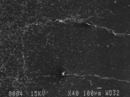
The same sample was also scrutinised using a scanning electron microscope, under which the individual grains could be observed. The structure of the non-comminuted zone was fairly uniform, with only a little porosity and macroscopic cracking. In the comminuted zone the structure was broken along grain boundaries into both individual grains, and larger multi-grain chunks.
Next exists a zone of highly fractured material. Very small and fine fractures can be seen to extend outward from the impact site and intersect with below surface lateral cracks. This leads to the formation of small particles of ceramic, the volume of which is dependent on the magnitude of the impact.
Hertzian [3] cone cracks emanate from the point of impact, extending outwards of angles up to 125°. Lateral cracks run below the impact surface intersecting with the Hertzian cracks. Radial cracks also extend from the surface to these lateral cracks and eventually cause spalling of the front surface.
The higher the impact velocity the greater the number of lateral cracks running below the surface and hence the more chance of fragmentation. If the impact is quite close to the outside of the ceramic block intersection of the lateral, radial and conoid cracks cause extensive spall and complete failure of the ceramic. If however, the impact is central, the block remains intact, contained by the surrounding material. Confinement will also reduce the chance of failure on impact and increase the ceramics ballistic performance [4]. Apart from the dissipation of tensile stress by the surrounding material, confinement restricts the expansion of the damaged ceramic leaving the target material still within the path of the projectile.
Depth of penetration
The penetration depth of each target was measured and plotted against velocity (Figure 2). The measurements were taken from the front surface of the target.
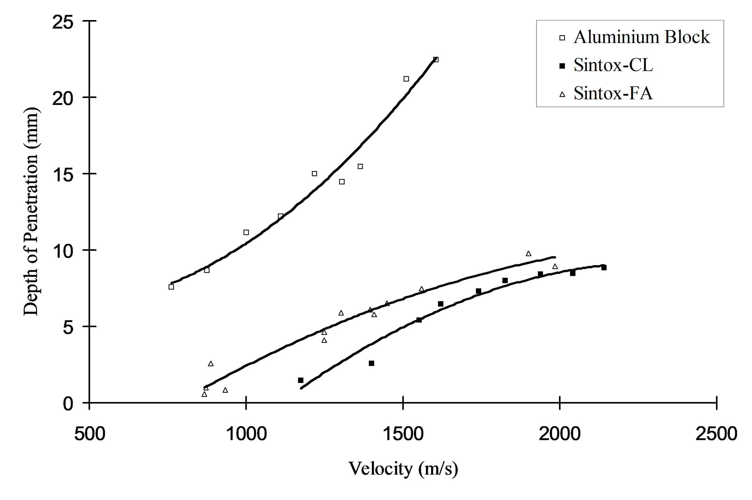
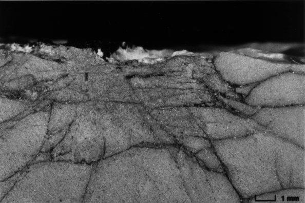
The penetration into the Sintox-CL targets was less than that of the Sintox-FA blocks; this is attributed to the higher alumina content and hence higher hardness. The slope of the penetration-velocities lines are similar. It was also noted that the size of the residual comminuted zone (the difference between the penetration depth and the depth of the comminuted zone measured from the impact surface) diminished over the range of impact velocities for both grades of ceramics. The authors believe that this is due to tensile failure that is developed by the unloading of the projectile, relieving the compressive stresses around the comminuted zone. Figure 3 shows the development of tensile cracks within the residual comminuted zone. For the Sintox-FA targets, the size of the residual comminuted zone is generally larger than that observed in the Sintox-CL targets. This is due to Sintox-FA having a larger fracture toughness than Sintox-CL. The published [1] fracture toughness values for Sintox-FA and Sintox-CL are 4.6MPam and 3.5MPam respectively.
From the penetration depths, a relative mass efficiency factor was derived for both of the ceramics. This factor ranked each ceramic in terms of the mass of ceramic required to stop the steel sphere compared to that of the aluminium block. The mass efficiency is calculated from:
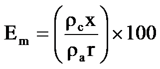 (1)
(1)where ρcandρaare the densities of the ceramic and aluminium respectively. x is the depth of penetration into the ceramic and r is the depth of penetration into the aluminium block. This is plotted against velocity in Figure 4 for both grades of ceramic.
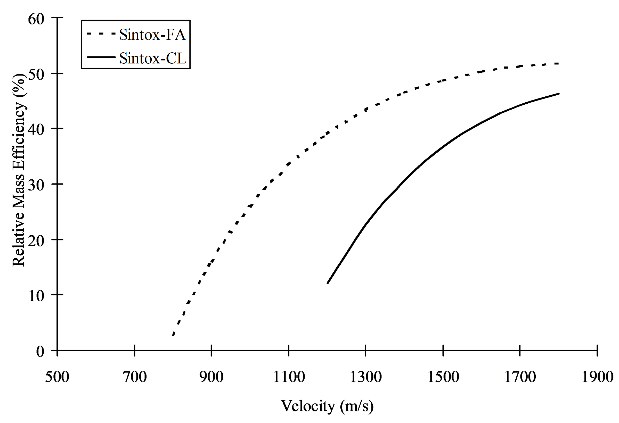
At the lower velocities (<800 ms-1) it can be seen that that for both ceramics, no penetration was measured. Penetration of the ceramic occurs at a lower velocity for Sintox-FA than for Sintox-CL. Between the velocity range of 800-1800 ms-1 there is a distinct weight advantage of using Sintox-CL rather than Sintox FA. However, this advantage diminishes as the velocity of impact increases. Although the Sintox-CL targets gave greater protection against this threat, more fracturing of the block was observed due to the lower fracture toughness.
Conoid formation
The sectioned targets revealed a number of Hertzian type fracture patterns emanating from the point of impact. On loading, crack growth follows the tensile stress trajectories as predicted by elastic loading stresses, thereby giving rise to tensile nucleation, growth and coalescence of micro-cracks. It has been shown [5,6] that such a fracture pattern is formed from the fracture front travelling at 1 to 2 kms-1 less than the longitudinal wave velocity of the ceramic. Field et al [7]impacted hard steel projectiles against different grades of ceramic and found that the relative hardness of the projectile and the target played a large part in conoid formation. Also, in their experiments, they measured the semi-apex angle (θ) of the cones that were formed and discovered that for glass ceramics, θ decreased with increasing impact velocity. For alumina, θ increased with impact velocity for a velocity range of 300-1200 ms-1.
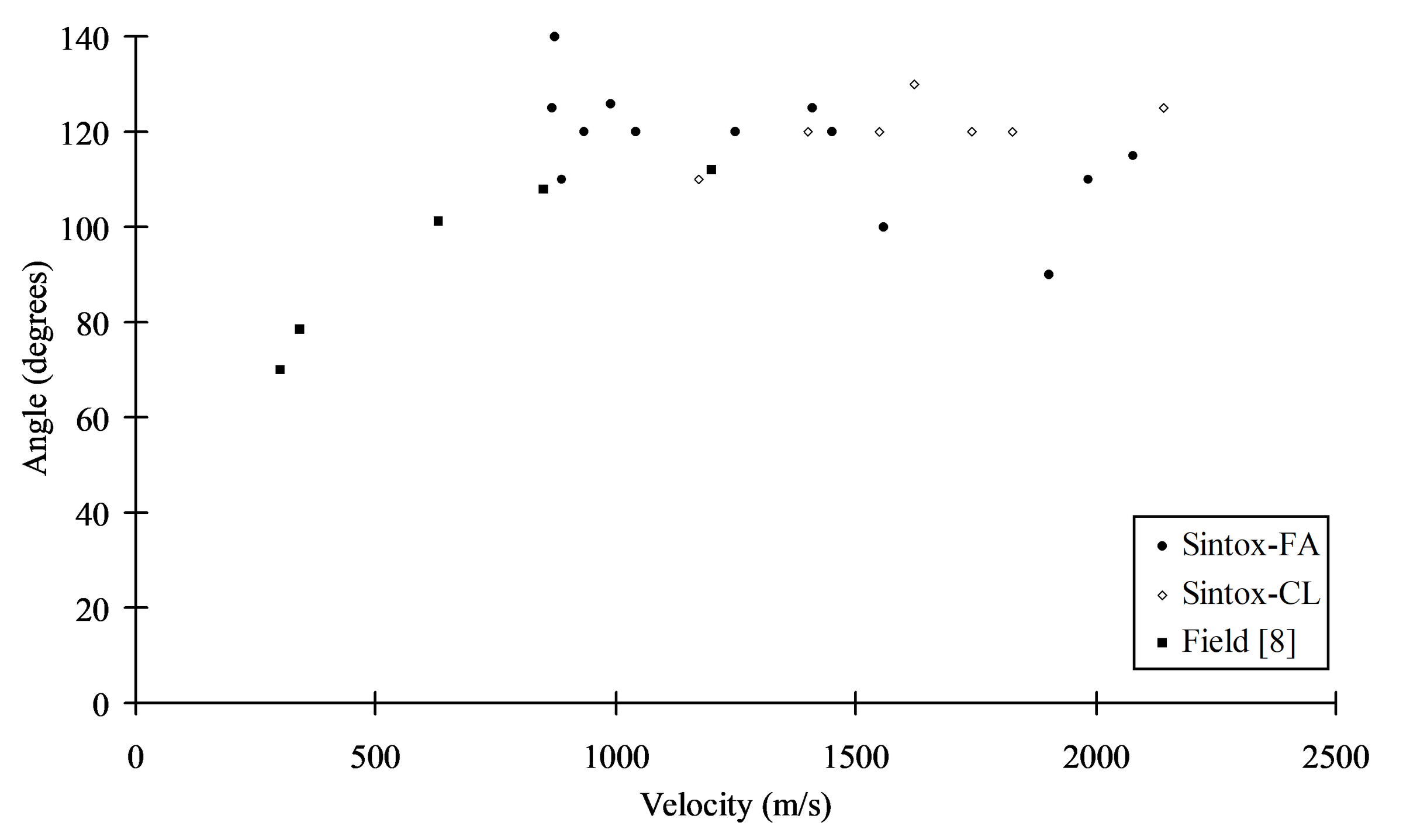
Plotting Field’s data [8] alongside our data for the two types of ceramic reveal that the semi-apex angle of the outer conoid increases to a limiting velocity, after which the cone angle remains constant (Figure 5). It is thought that this phenomenon is a function of the brittle nature of the projectile. Sharp projectiles impacting the same material (Sintox-FA) yield a solid cone with a semi-apex angle of 50°, much less than the spherical projectile. Increasing the velocity leads to larger deformations, changing the contact area and henceforth modifying the applied stress field. Finally the projectile shatters on impact and is unable to deform further. At this point, increasing the velocity will result in no further increase in the semi-apex angle of the conoid.
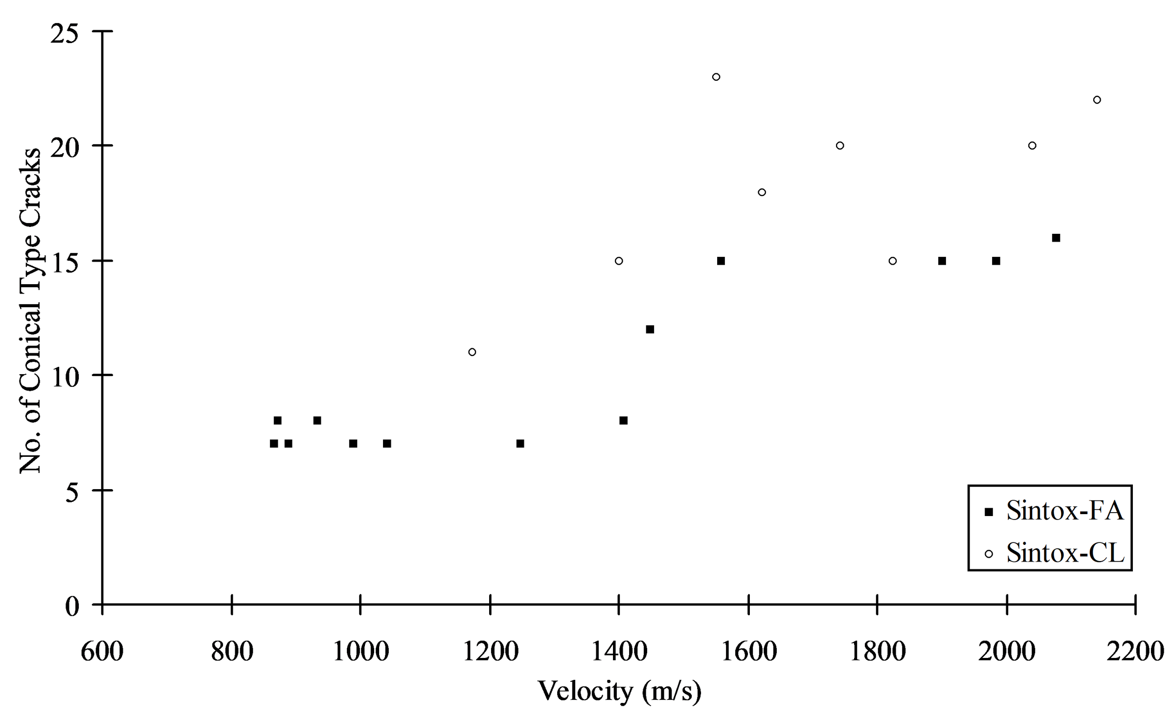
Increasing the velocity of impact leads to an increase in the number of Hertzian type cracks at a critical velocity (Figure 6). This increase in this experimental programme is yet unexplained. One possibility, is that the sharp increase shown in Figure 6 may be due to crack forking. On closer inspection, it was noted that there were a large number of cracks that had forked, some quite close to the point of impact. A crack that is nucleated and running under an increasing stress reaches an effective limiting velocity. Increasing the driving load on the crack may cause it to divide into two separate propagating cracks [9]. Therefore, cracks nucleated by a sufficiently high impact shock, may immediately fork and propagate as two independent cracks.
Concluding remarks
Two different grades of Alumina have been subjected to high velocity impact by 6.35 mm diameter steel spheres and the damage created has been analysed. Overall, the Sintox-CL provided better protection than the Sintox-FA. This was mainly due to the increased hardness although having a lower fracture toughness compromised its post-impact strength. The depth of the residual comminuted zone for both grades of ceramic degraded with increasing impact velocity. This was due to the formation of tensile cracks within the zone when projectile loading ceased. A ranking method has been employed which calculates the relative mass advantage of using a ceramic over an aluminium material. For this experimental programme, the relative weight saving of the Sintox-CL over the Sintox-FA diminished with increasing velocity.
The semi-apex angle of the outer conoid increases with increasing velocity until the projectile becomes highly fractured on impact. Increasing the velocity leads to larger deformations, changing the contact area and henceforth modifying the applied stress field. When the projectile breaks, it is unable to modify the stress field further and therefore the semi-apex angle of the outer conoid remains constant.
For both grades of Alumina a step increase is observed in the number of Hertzian-type cracks at roughly the same velocity. The authors believe that this is due to a limiting driving load applied to each individual crack at a specific velocity (~1500 ms-1). Increasing the impact velocity and hence the driving load causes it to divide into two separate propagating cracks.
Acknowledgements
The authors would like to thank Mr. Steven Champion, Mr. John Crocker and Mr. Dave Miller for their assistance during this project. The authors would also like to thank Dr David Townsend and Mr Mike Beswick of British Aerospace for their helpful comments. This work was carried out from funding available from the Hypervelocity Impact Society and British Aerospace Defence plc.
References
[1] Product Data Sheet, Morgan Matroc Ltd. Bewdley Road, Stourport-on-Severn, Worcestershire, DY13 8QR UK.
[2] P. Hazell and M. Iremonger, “Ceramic Comminution due to Projectile Penetration”, Proceedings of the Lightweight Armour Systems Symposium ’97, Royal Military College of Science, Shrivenham, UK, 1997.
[3] F. Frank and B. Lawn, “On the Theory of Hertzian Fracture”, Proceedings of the Royal Society London, Section A299, pp. 291-306, 1967.
[4] C. Anderson Jr and S. Royal-Timmons, “Ballistic Performance of Confined 99.5%-Al2O3 Ceramic Tiles”, International Journal of Impact Engineering, Vol.19, No. 8, pp. 703-713, 1997.
[5] E. Strassburger, H. Senf and H. Rothenausler, “Comparison of Failure Behaviour During Impact and Ballistic Performance of Different Al2O3 Ceramics”, Proceedings of the Lightweight Armour Systems Symposium, RMCS, Shrivenham, 1995.
[6] U. Hornemann, H. Rothenhausler, H. Senf, J. F. Kalthoff and S. Winkler, “Experimental Investigation of Wave and Fracture Propagation in Glass Slabs Loaded by Steel Cylinders at High Impact Velocities”, Inst. Phys. Conf. Ser. No. 70, 3rd Conf. Mech. Prop. Materials at High Rates of Strain. Oxford, 1984.
[7] J. Field, Q. Sun and D. Townsend, “Ballistic Impact of Ceramics”, International Conference on Mechanical Properties of Materials at High Rates of Strain. Oxford, 1989.
[8] J. Field, Investigation of the Impact Performance of Various Glass and Ceramic Systems, Final Technical Report, Contract DAJA45-85-C-0021, United States Army, 1988.
[9] V. D. Frechette, “Failure Analysis of Brittle Materials”, Advances in Ceramics, Vol. 28, The American Ceramic Society, Westerville, Ohio, 1990.