
Volume 1, Number 1, March 1998
Some Metallurgical Aspects of Shaped Charge Liners
Abstract
This paper reviews the traditional selection criteria for shaped charge liners, and demonstrates some confusions that arise. When considering possible new liner materials it is proposed that measurement of dynamic mechanical properties, rather than the usual more readily available static data, would be helpful, particularly to mathematical modellers.
Introduction
The shaped charge jet
The first section of this paper reviews what is expected from a conical shaped charge liner. As illustrated in Figure 1, the shaped charge jet tip reaches 10 kms-lsome 40 µs after detonation, giving a cone tip acceleration of about 25 million g.
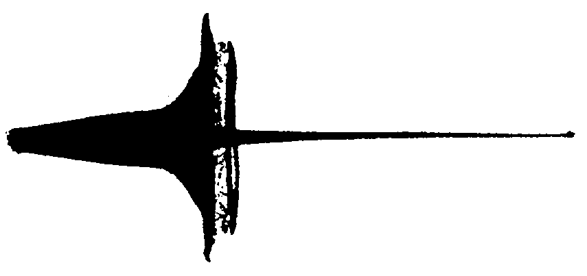
At this acceleration the tip would reach the speed of light, were this possible, in around 1.5 seconds. But of course, it reaches a terminal velocity after only 40 millionths of a second. It is difficult to think of any other terrestrial event as fast as a shaped charge jet tip. The jet tail has a velocity of 2-5 kms-l and so, as illustrated in Figure 2, the jet stretches out to a length of about 8 cone diameters (CDs) before particulation occurs.
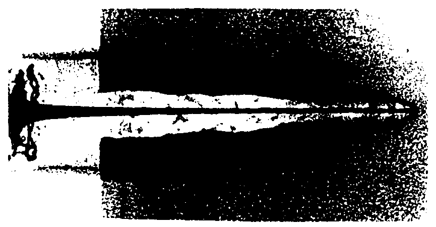
The stretching occurs at a high strain rate, requiring the cone material to have excellent dynamic ductilityat temperatures up to about 450°C. On reaching a target, the pressure developed between the jet tip and the forming crater can be as high as 10 Mbar(10million atmospheres), several times the highest pressure predicted in the Earth's core.
Shaped charge is indeed an extraordinary phenomenon that is beyond the scale of normal physics, which explains why its fundamental theoretical mechanism is by no means fully understood.
The explosively formed projectile (EFP)
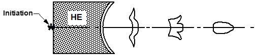
Wide angle cones and other liner shapes such asplates or dishes do not jet, but give instead an explosively formed projectile or EFP, as illustrated in Figure 3. The projectile forms by dynamic plastic flowand has a velocity of 1-3 kms-l. Target penetration is much less than that of a jet, but the hole diameter is larger with more armour backspall.
Hydrodynamic flow
It is universally agreed that conical liner collapse and target penetration both occur by hydrodynamic flow. However, it has been established by X-ray diffraction that the jet is solid metal and not molten. Additionally, best estimates of jet temperature by incandescence colour suggest a mean value of about 450°C, and copper melts at 1083°C at atmospheric pressure. So the following conundrum is the first confusion:
The jet appears to behave like a fluid, and yet it is known to be a solid.
One recent theory that would help explain this is that the jet has a molten core but with a solid outer sheath (Cullis, DERA Fort Halstead, UK).
The target penetration flash X-ray of Figure 2 shows that hypervelocity hydrodynamic impact (unlike lower speed KE penetration) results in a mushroom head penetration, such that the hole diameter is larger than the penetrator diameter. The dynamic compressive yield stressof the target is exceeded by a factor of at least one thousand times, so that only the densities of the target and jet materials are important. Both materials flow as if they were fluids and the penetration event can be modelled quite accurately using the Bernoulli equation for incompressible flow to give the well known hydrodynamic penetration equation:
(1)
where p is the penetration, L is the jet length, ρjand ρt are the densities of the jet and target respectively, and λ is a constant associated with jet lengthening, and having a value between 1 and 2.
Equation 1 is quite accurate for a wide range of liners and targets, despite its incorrect assumption that there is no velocity gradient along the jet.
Traditional liner materials selection criteria
From the hydrodynamic penetration equation it is clear that target penetration pis improved if the jet densityρjis increased, but only if jet lengthLremains high. As a reference, a good copper jet - inherently ductile due to its face centred cubic (FCC) crystal structure - will be eight CDs long.
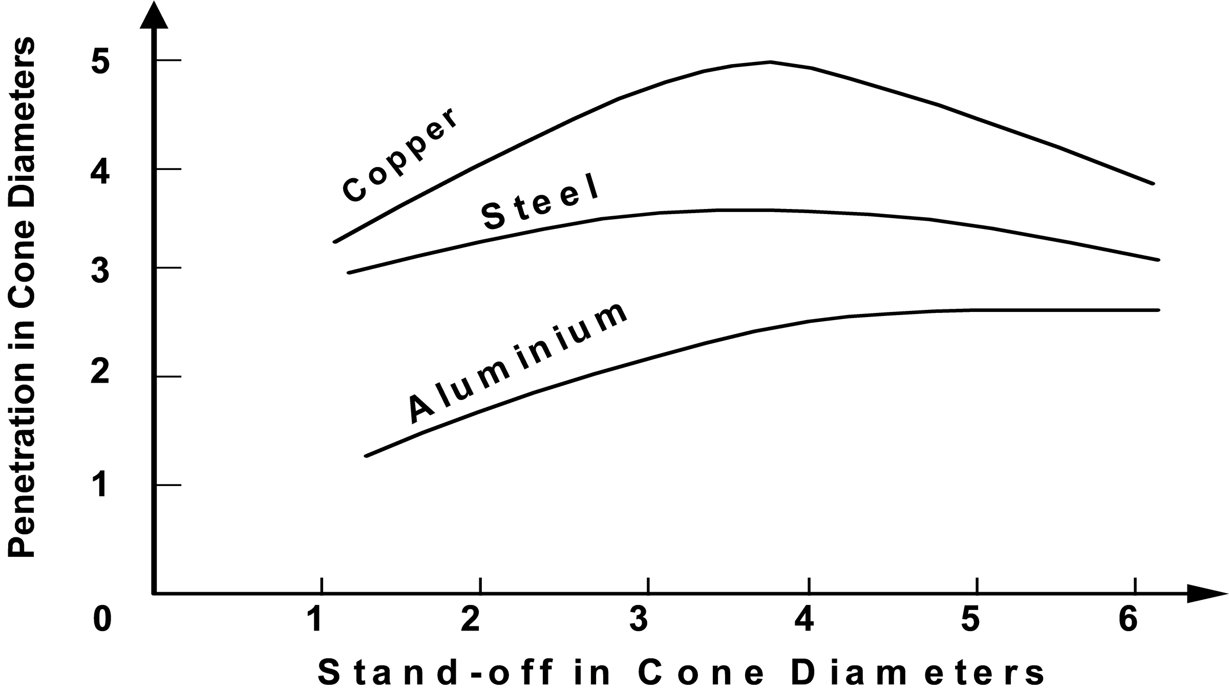
For ductile metal linerswhere L is fairly similar, Equation (1) correctly predicts penetration into monolithic steel targets in the order of their cone density. Figure 4 shows typical results for cones of copper, steel and aluminium, having densities of approximately 8900, 7900 and 2700 kgm-3 respectively.
Jet density is the same as the cone density for metals, but for cones of polymeric material flash X-ray contrast shows the jet to be less dense than the initial solid polymer cone.
Liner materials research is thus often driven towards higher density metalsbut many of these are not FCC and are much less ductile than copper, giving reduced jet lengths,hence negating their higher density.
Some candidate pure metals with their salient details are shown in Table 1.
So, in theory, a goldcone, for instance, would be capable of penetrating 47% deeper than copper into the same target, if the jet was no shorter. Although its FCC crystal structure would give a reason to be optimistic about this, gold is usually regarded as being too expensive!
Some liner materials tried - confusion
Despite much research and development expenditure on alternatives, copperhas remained a favourite conical liner material for several decades, even though its behind armour effects are very limited, and ironand tantalumalloys perform better for EFP liners. Cartridge brassis more ductile than copper; yet it performs worse than copper when tried as a cone for a shaped charge device. Leadis an interesting candidate; it is FCC with a higher density than copper, its low melting point would ensure a molten jet, and it is truly 'hydrodynamic'. Yet, in practice, it under performs by a considerable margin. Because of better ductility, copper cones with a finer grain sizeperform better than those with larger grains, and yet a finer grain size also confers higher strength. Graphite cones,and even ceramic coneswith zero ductility, have shown significant penetration into steel targets.
Mathematical hydrocode modelsneed to encompass a host of strength properties for the liner and the target materials at various strains, strain rates and temperatures, even though hydrodynamic deformation is supposed not to depend on them. The confusion gets even worse when considering the attack of multi-layered armours, and their advent (together with reduced availability of real firing trials) has meant increased reliance on mathematical modelling.
There is a need for realistic and reliable stress-strain data for the liner and armour materials, and this should be dynamic data measured at the appropriate high strain rates.
Dynamic mechanical properties and their measurement
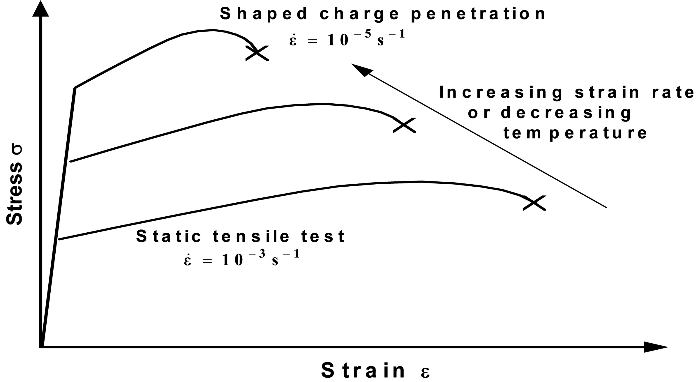
Routine statictensile testing uses modest crosshead speeds giving a strain rate of about 10-3 s-l. This is the readily available data, but shaped charge events occur at strain rates of up to about 105 s-l, two orders of magnitude faster. Generally, as strain rate increases, metals get stronger and less ductile, but with no change in stiffness (Young’s modulus, E). This effect is similar to lowering the test temperature and is shown in Figure 5.
The relationship between true stress, σ, to true strain, ε, and strain rate, , during plastic deformation of metals is given by the Holloman, or Ludwig, equation,
where σ0 and Kare alloy constants, n is the work hardening index, and m is the strain rate sensitivity index, both alloy constants. At a constant plastic strain of 0.2% proof or yield stress, σr, as appropriate,the Holloman equation reduces to:
and a log-log plot gives a straight line as shown in Figure 6.
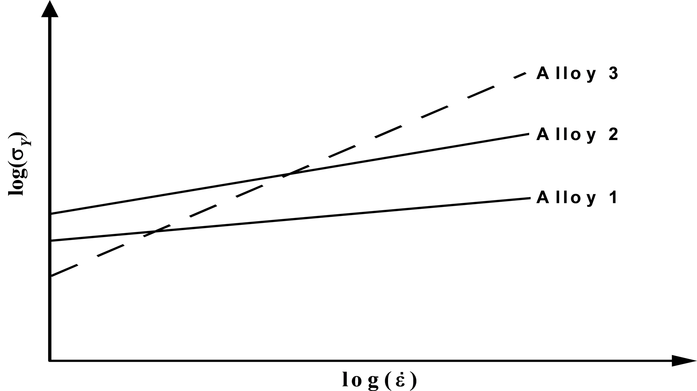
The strain rate sensitivity index, m varies with different alloys and with different microstructures of the same alloy. For example, Alloy 3 in Figure 6 has a low static yield strength, defined by the intercept on the vertical axis, but will have a higher dynamic yield strength than Alloys 1 and 2 if it has a sufficiently high strain rate sensitivity index.
High speed dynamic testingrequires special equipment such as a Rosand Instrumented Drop Tower. This is capable of much higher crosshead speeds than conventional servohydraulic test machines. The Royal Military College of Science (RMCS) machine uses a variable drop weight, up to 40 kg, with a 'bungy' spring assist to achieve anvil strike speeds up to 20 ms-l.
The machine is simplest to use for dynamic compression testingof cylindrical specimens between plane platens. A bend rig attachment is used for high speed 3-point bend testing. Using a suitable attachment and a tensile specimen with a gauge length of 17 mm, dynamic tensile testingstrain rates of up to 5.1x10⁻³ s-l are easily achievable, some six orders of magnitude faster than conventional static tensile testing.
These techniques allow the use of bulk specimens, providing a powerful tool for the mathematical modeller to acquire the dynamic properties of the materials of interest.
In practice, dynamic testing is accompanied by adiabatic heating of the specimen, often giving failure by adiabatic shearing,and so the data is best supported with diagnostic optical and electron microscopy to understand the mechanism of dynamic fracture.
RMCS development plans include the use of an environmental chamber around the specimen to carry out hot dynamic tensile testing.
Conclusion
There is much confusion in the field of shaped charge liner materials and hydrodynamic penetration and a scarcity of accurate dynamic materials properties does not help when considering possible new liner materials. Mathematical modellers, therefore, often fit their output to the results of firing trials (cross-calibration to reality) by adjusting some of the materials coefficients. Although the overall answer may then be correct, some of the coefficients in the model are high and some are low, and the problem is in knowing which are which. Event fitting is necessary but it does not allow the models to be used predictively.
Using measured dynamic properties of materials would enable the mathematical modeller to enter the era of true prediction, and the instrumented Drop Tower can help with this.